Language selection

Search

Patent 2935239 Summary

Third-party information liability

Some of the information on this Web page has been provided by external sources. The Government of Canada is not responsible for the accuracy, reliability or currency of the information supplied by external sources. Users wishing to rely upon this information should consult directly with the source of the information. Content provided by external sources is not subject to official languages, privacy and accessibility requirements.

Claims and Abstract availability

Any discrepancies in the text and image of the Claims and Abstract are due to differing posting times. Text of the Claims and Abstract are posted:

  • At the time the application is open to public inspection;
  • At the time of issue of the patent (grant).
(12) Patent: (11) CA 2935239
(54) English Title: SUN SHADE ASSEMBLY
(54) French Title: ENSEMBLE DE PARE-SOLEIL
Status: Granted
Bibliographic Data
(51) International Patent Classification (IPC):
  • B60J 3/02 (2006.01)
  • B60J 3/00 (2006.01)
(72) Inventors :
  • RICHMAN, JACK (Canada)
(73) Owners :
  • RICHMAN, JACK (Canada)
(71) Applicants :
  • RICHMAN, JACK (Canada)
(74) Agent: BLANEY MCMURTRY LLP
(74) Associate agent:
(45) Issued: 2021-02-09
(22) Filed Date: 2016-07-07
(41) Open to Public Inspection: 2018-01-07
Examination requested: 2019-01-25
Availability of licence: N/A
(25) Language of filing: English

Patent Cooperation Treaty (PCT): No

(30) Application Priority Data: None

Abstracts

English Abstract

A sun shade assembly includes a first visor structured to have a front side and a back side. The first visor is movably coupled to a vehicle. The first visor is positionable in front of the driver of the vehicle the first visor may provide shade for the driver. A second visor is structured to have a forward side and a rearward side. The second visor is movably coupled to the first visor. The second visor is positionable beside the driver of the vehicle. The second visor may provide shade for the driver. A window is movably coupled to the first visor. The window is positionable in a stored position so the window is concealed within the first visor. The window is positionable in a deployed position so the window extends outwardly from the first visor. The window may provide additional shade for the driver.


French Abstract

Un ensemble de pare-soleil comprend une première visière structurée pour avoir un côté avant et un côté arrière. La première visière est couplée de façon mobile à un véhicule. La première visière peut être positionnée devant le conducteur du véhicule, la première visière pouvant fournir un store pour le conducteur. Une seconde visière est structurée pour avoir un côté avant et un côté arrière. La seconde visière est couplée de façon mobile à la première visière. La seconde visière peut être positionnée à côté du conducteur du véhicule. La seconde visière peut fournir un store pour le conducteur. Une fenêtre est couplée de façon mobile à la première visière. La fenêtre peut être positionnée dans une position stockée de telle sorte que la fenêtre est dissimulée à lintérieur de la première visière. La fenêtre peut être positionnée dans une position déployée de telle sorte que la fenêtre sétend vers lextérieur à partir de la première visière. La fenêtre peut fournir un ombrage supplémentaire pour le conducteur.

Claims

Note: Claims are shown in the official language in which they were submitted.

I claim:
1. A sun shade assembly comprising: a first visor structured to have a
front side and a
back side, said first visor being movably coupled to a vehicle, said first
visor being
positionable in front of a driver of the vehicle such that said first visor is
configured to
provide shade for the driver; a second visor being structured to have a
forward side and a
rearward side, said second visor being movably coupled to said first visor,
said second
visor being positionable beside the driver of the vehicle such that said
second visor is
configured to provide shade for the driver; a hinge coupled between a top edge
of said first
visor and an upper edge of said second visor such that said second visor is
hingedly coupled
to said first visor, said hinge having an arcuate section, said arcuate
section having
downwardly extending ends, each of said downwardly extending ends of said
arcuate
section being coupled to an associated one of said first visor and said second
visor such
that said second visor is pivotable relative to said first visor wherein an
edge of said second
visor remains in contact with said first visor as said second visor is
pivoted; and a window
movably coupled to said first visor, said window being positionable in a
stored position
such that said window is concealed within said first visor, said window being
positionable
in a deployed position such that said window extends outwardly from said first
visor
wherein said window is configured to provide additional shade for the driver.
2. The sun shade assembly according to claim 1, further comprising a rod
extending
laterally through said first visor such that said rod is positioned proximate
to and is
coextensive with the top edge of said first visor, said first visor being
hingedly coupled to
said rod.
3. The sun shade assembly according to claim 2, further comprising said rod
being
bent such that a first end of said rod is directed upwardly from said rod.
4. The sun shade assembly according to claim 3, further comprising said
first end of
said first rod being coupled to the vehicle such that said first visor extends
laterally in front
of the driver.

5. The sun shade assembly according to claim 4, further comprising said
second visor
being positionable in the stored position such that said forward side of said
second visor
abuts said front side of said first visor.
6. The sun shade assembly according to claim 5, further comprising said
second visor
being positionable in the deployed position such that said forward side of
said second visor
lies on a plane being perpendicular to said front side of said first visor.
7. The sun shade assembly according to claim 1, further comprising said
window
being slidably coupled to said first visor such that said window is extendable
downwardly
from a bottom edge of said first visor.
8. A sun shade assembly comprising: a first visor structured to have a
front side and a
back side; a rod extending laterally through said first visor such that said
rod is positioned
proximate to and is coextensive with a top edge of said first visor, said
first visor being
hingedly coupled to said rod, said rod being bent such that a first end of
said rod is directed
upwardly from said rod, said first end of said first rod being coupled to a
vehicle, said first
visor extending laterally in front of the driver such that said first visor is
configured to
provide shade for a driver; a second visor being structured to have a forward
side and a
rearward side; a hinge coupled between the top edge of said first visor and an
upper edge
of said second visor such that said second visor is hingedly coupled to said
first visor, said
hinge having an arcuate section, said arcuate section having downwardly
extending ends,
each of said downwardly extending ends of said arcuate section being coupled
to an
associated one of said first visor and said second visor such that said second
visor is
pivotable relative to said first visor wherein an edge of said second visor
remains in contact
with said first visor as said second visor is pivoted; said second visor being
positionable in
a stored position such that said forward side of said second visor abuts said
front side of
said first visor; said second visor being positionable in a deployed position
having said
forward side of said second visor lying on a plane being perpendicular to said
front side of
said first visor such that said second visor is configured to provide shade
for the driver; and
a window, said window being slidably coupled to said first visor, said window
being
positionable in the stored position such that said window is concealed within
said first
6

visor, said window being positionable in the deployed position such that said
window
extends downwardly from a bottom edge of said first visor wherein said window
is
configured to provide additional shade for the driver.
7

Description

Note: Descriptions are shown in the official language in which they were submitted.


CA 02935239 2016-07-07
SUN SHADE ASSEMBLY
BACKGROUND OF THE DISCLOSURE
Field of the Disclosure
The disclosure relates to shade devices and more particularly pertains to a
new shade
device for providing shade for a driver of a vehicle.
SUMMARY OF THE DISCLOSURE
An embodiment of the disclosure meets the needs presented above by generally
comprising a first visor structured to have a front side and a back side. The
first visor is
movably coupled to a vehicle. The first visor is positionable in front of a
driver of the
vehicle the first visor may provide shade for the driver. A second visor is
structured to
have a forward side and a rearward side. The second visor is movably coupled
to the first
visor. The second visor is positionable beside the driver of the vehicle. The
second visor
may provide shade for the driver. A window is movably coupled to the first
visor. The
window is positionable in a stored position so the window is concealed within
the first
visor. The window is positionable in a deployed position so the window extends
outwardly from the first visor. The window may provide additional shade for
the driver.
There has thus been outlined, rather broadly, the more important features of
the
disclosure in order that the detailed description thereof that follows may be
better
understood, and in order that the present contribution to the art may be
better appreciated.
There are additional features of the disclosure that will be described
hereinafter and
which will form the subject matter of the claims appended hereto.
The objects of the disclosure, along with the various features of novelty
which
characterize the disclosure, are pointed out with particularity in the claims
annexed to and
forming a part of this disclosure.
1

CA 02935239 2016-07-07
BRIEF DESCRIPTION OF THE DRAWINGS
The disclosure will be better understood and objects other than those set
forth above will
become apparent when consideration is given to the following detailed
description
thereof. Such description makes reference to the annexed drawings wherein:
FIG. 1 is a perspective view of a sun shade assembly according to an
embodiment of the
disclosure.
FIG. 2 is a top view of an embodiment of the disclosure.
FIG. 3 is a bottom perspective view of an embodiment of the disclosure.
FIG. 4 is a bottom view of an embodiment of the disclosure.
FIG. 5 is a right side view of an embodiment of the disclosure.
FIG. 6 is a front view of an embodiment of the disclosure.
FIG. 7 is an in-use view of an embodiment of the disclosure.
DESCRIPTION OF THE PREFERRED EMBODIMENT
With reference now to the drawings, and in particular to FIGS. 1 through 7
thereof, a new
shade device embodying the principles and concepts of an embodiment of the
disclosure
and generally designated by the reference numeral 10 will be described.
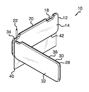
As best illustrated in FIGS. 1 through 7, the sun shade assembly 10 generally
comprises a
first visor 12 structured to have a front side 14 and a back side 16. A rod 18
is provided.
The rod 18 extends laterally through the first visor 12. Additionally, the rod
18 is
positioned proximate to and is coextensive with a top edge 20 of the first
visor 12. The
first visor 12 is hingedly coupled to the rod 18.
The rod 18 is bent such that a first end 22 of the rod 18 is directed upwardly
from the rod
18. The first end 22 of the first rod 18 is coupled to an interior of a
vehicle 24. The
2

CA 02935239 2016-07-07
=
vehicle 24 may be a passenger vehicle of any conventional design. The first
visor 12
extends laterally in front of a driver 26 of the vehicle 24. Additionally, the
first visor 12 is
positionable in a stored position so the first visor 12 is removed from the
driver's 26 line
of sight. The first visor 12 is positionable in a deployed so the first visor
12 may provide
shade for the driver 26.
A second visor 28 is structured to have a forward side 30 and a rearward side
32. A hinge
34 is coupled between the top edge 20 of the first visor 12 and an upper edge
38 of the
second visor 28. The second visor 28 is hingedly coupled to the first visor
12. The second
visor 28 is positionable in a stored position so the forward side 30 of the
second visor 28
abuts the front side 14 of the first visor 12. Moreover, the second visor 28
is positionable
in a deployed position so the forward side 30 of the second visor 28 lies on a
plane that is
perpendicular to the front side 14 of the first visor 12. The second visor 28
may provide
shade for the driver 26.
A window 40 is provided. The window 40 is slidably coupled to the first visor
12. The
window 40 is positionable in a stored position so the window 40 is concealed
within the
first visor 12. The window 40 is positionable in a deployed position so the
window 40
extends downwardly from a bottom edge 42 of the first visor 12. The window 40
may
provide additional shade for the driver 26. Finally, the window 40 is
coextensive with the
bottom edge 42 of the first visor 12.
The window 40 may be comprised of a translucent material. The window 40 is
additionally tinted. The window 40 reduces an amount of sun light directed
toward the
driver 26.
In use, the first visor 12 in positioned in the deployed position to provide
shade in the
driver's 26 line of sight. The second visor 28 is positionable in the deployed
position if
the driver 26 needs shade from the side. The window 40 is deployed if the
driver 26
needs additional protection from sun light when the first visor 12 is in the
deployed
position. The window 40 may be deployed regardless of the positioning of the
second
visor 28.
3

CA 02935239 2016-07-07
With respect to the above description then, it is to be realized that the
optimum
dimensional relationships for the parts of an embodiment enabled by the
disclosure, to
include variations in size, materials, shape, form, function and manner of
operation,
assembly and use, are deemed readily apparent and obvious to one skilled in
the art, and
all equivalent relationships to those illustrated in the drawings and
described in the
specification are intended to be encompassed by an embodiment of the
disclosure.
Therefore, the foregoing is considered as illustrative only of the principles
of the
disclosure. Further, since numerous modifications and changes will readily
occur to those
skilled in the art, it is not desired to limit the disclosure to the exact
construction and
operation shown and described, and accordingly, all suitable modifications and

equivalents may be resorted to, falling within the scope of the disclosure. In
this patent
document, the word "comprising" is used in its non-limiting sense to mean that
items
following the word are included, but items not specifically mentioned are not
excluded. A
reference to an element by the indefinite article "a" does not exclude the
possibility that
more than one of the element is present, unless the context clearly requires
that there be
only one of the elements.
4

Representative Drawing
A single figure which represents the drawing illustrating the invention.
Administrative Status

For a clearer understanding of the status of the application/patent presented on this page, the site Disclaimer , as well as the definitions for Patent , Administrative Status , Maintenance Fee  and Payment History  should be consulted.

Administrative Status

Title Date
Forecasted Issue Date 2021-02-09
(22) Filed 2016-07-07
(41) Open to Public Inspection 2018-01-07
Examination Requested 2019-01-25
(45) Issued 2021-02-09

Abandonment History

Abandonment Date Reason Reinstatement Date
2018-07-09 FAILURE TO PAY APPLICATION MAINTENANCE FEE 2019-01-23

Maintenance Fee

Last Payment of $100.00 was received on 2023-06-19


 Upcoming maintenance fee amounts

Description Date Amount
Next Payment if small entity fee 2024-07-08 $100.00
Next Payment if standard fee 2024-07-08 $277.00

Note : If the full payment has not been received on or before the date indicated, a further fee may be required which may be one of the following

  • the reinstatement fee;
  • the late payment fee; or
  • additional fee to reverse deemed expiry.

Patent fees are adjusted on the 1st of January every year. The amounts above are the current amounts if received by December 31 of the current year.
Please refer to the CIPO Patent Fees web page to see all current fee amounts.

Payment History

Fee Type Anniversary Year Due Date Amount Paid Paid Date
Application Fee $200.00 2016-07-07
Reinstatement: Failure to Pay Application Maintenance Fees $200.00 2019-01-23
Maintenance Fee - Application - New Act 2 2018-07-09 $50.00 2019-01-23
Maintenance Fee - Application - New Act 3 2019-07-08 $50.00 2019-01-23
Request for Examination $400.00 2019-01-25
Maintenance Fee - Application - New Act 4 2020-07-07 $50.00 2020-04-02
Final Fee 2020-12-14 $150.00 2020-12-14
Maintenance Fee - Patent - New Act 5 2021-07-07 $100.00 2021-05-04
Maintenance Fee - Patent - New Act 6 2022-07-07 $100.00 2022-07-06
Maintenance Fee - Patent - New Act 7 2023-07-07 $100.00 2023-06-19
Owners on Record

Note: Records showing the ownership history in alphabetical order.

Current Owners on Record
RICHMAN, JACK
Past Owners on Record
None
Past Owners that do not appear in the "Owners on Record" listing will appear in other documentation within the application.
Documents

To view selected files, please enter reCAPTCHA code :


To view images, click a link in the Document Description column. To download the documents, select one or more checkboxes in the first column and then click the "Download Selected in PDF format (Zip Archive)" or the "Download Selected as Single PDF" button.

List of published and non-published patent-specific documents on the CPD .

If you have any difficulty accessing content, you can call the Client Service Centre at 1-866-997-1936 or send them an e-mail at CIPO Client Service Centre.


Document
Description 
Date
(yyyy-mm-dd) 
Number of pages   Size of Image (KB) 
Examiner Requisition 2019-12-05 7 280
Maintenance Fee Payment 2020-04-02 1 33
Amendment 2020-04-02 10 255
Claims 2020-04-02 3 107
Final Fee 2020-12-14 3 86
Representative Drawing 2021-01-14 1 7
Cover Page 2021-01-14 1 35
Maintenance Fee Payment 2021-05-04 1 33
Maintenance Fee Payment 2022-07-06 2 43
Abstract 2016-07-07 1 17
Description 2016-07-07 4 141
Claims 2016-07-07 3 101
Drawings 2016-07-07 4 54
Representative Drawing 2017-12-06 1 6
Cover Page 2017-12-06 2 38
Maintenance Fee Payment 2019-01-23 1 33
Request for Examination 2019-01-25 1 40
New Application 2016-07-07 6 110
Maintenance Fee Payment 2023-06-19 3 48