Language selection

Search

Patent 2945287 Summary

Third-party information liability

Some of the information on this Web page has been provided by external sources. The Government of Canada is not responsible for the accuracy, reliability or currency of the information supplied by external sources. Users wishing to rely upon this information should consult directly with the source of the information. Content provided by external sources is not subject to official languages, privacy and accessibility requirements.

Claims and Abstract availability

Any discrepancies in the text and image of the Claims and Abstract are due to differing posting times. Text of the Claims and Abstract are posted:

  • At the time the application is open to public inspection;
  • At the time of issue of the patent (grant).
(12) Patent: (11) CA 2945287
(54) English Title: SIDE BEARING FOR RAILWAY CAR TRUCK
(54) French Title: PALIER LATERAL DESTINE A UN WAGON-BOGIE
Status: Granted
Bibliographic Data
(51) International Patent Classification (IPC):
  • B61F 5/14 (2006.01)
(72) Inventors :
  • WIKE, PAUL (United States of America)
  • HARRIS, ZACHARY (United States of America)
(73) Owners :
  • AMSTED RAIL COMPANY, INC. (United States of America)
(71) Applicants :
  • AMSTED RAIL COMPANY, INC. (United States of America)
(74) Agent: GOWLING WLG (CANADA) LLP
(74) Associate agent:
(45) Issued: 2018-11-20
(22) Filed Date: 2016-10-13
(41) Open to Public Inspection: 2017-04-22
Examination requested: 2016-10-13
Availability of licence: N/A
(25) Language of filing: English

Patent Cooperation Treaty (PCT): No

(30) Application Priority Data:
Application No. Country/Territory Date
14/920,171 United States of America 2015-10-22

Abstracts

English Abstract

An improved leaf spring side bearing assembly for railway freight cars is provided that achieves improved tracking and curving by the limitation of rock of the railway freight car. The side bearing comprises a base with two raised end sections. A leaf spring assembly is provided on the base that extends to the underside and support channel of the freight car. A top wear plate and a bottom travel stop are also included with the leaf spring side bearing assembly.


French Abstract

Un assemblage de palier latéral à ressort à lames destiné à des wagons de marchandise est présenté qui réaliser un suivi et une courbe améliorés en limitant le basculement du wagon de marchandise. Le palier latéral comprend une base dotée de deux sections dextrémité surélevées. Un assemblage de ressort à lames est présent sur la base qui se prolonge vers le dessous et supporte un canal du wagon de marchandise. Une plaque dusure supérieure et une butée de parcours inférieure sont également incluses dans lassemblage de palier latéral à ressort à lames.

Claims

Note: Claims are shown in the official language in which they were submitted.

What is claimed is:
1. A side bearing assembly comprising:
a base structure having two ends,
four shackles, each shackle connected to one of the base structure ends,
a leaf spring assembly having two ends,
two leaf spring end clamps, each leaf spring end clamp connected to each end
of the leaf
spring assembly,
each leaf spring end clamp also connected to two of the shackles,
a top clamp joining a top portion of the leaf spring assembly,
and a bottom stop connected to a bottom of the top clamp.
2. The side bearing assembly of claim 1 further comprising
a wear plate positioned between the top portion of the leaf spring assembly
and the
clamp.
3. The side bearing assembly of claim 1 further comprising
a first pin joining the shackle to the base structure end in a manner to allow
rotation
between the shackle and the base structure end.
4. The side bearing assembly of claim 1 further comprising

a second pin joining the shackle to the leaf spring end clamp in a manner to
allow
rotation between the shackle and the leaf spring end clamp.
5. The side bearing assembly of claim 1 wherein the maximum travel of the leaf
spring
assembly downward from an unloaded position is less than 0.625 inch.
6. The side bearing assembly of claim 1 wherein the leaf spring assembly is
comprised
of a glass fiber reinforced polymer leaf spring.
7. A side bearing assembly comprising:
a base structure having two ends,
a plurality of shackles, each shackle connected to one of the base structure
ends,
a leaf spring having two ends and a top portion,
two leaf spring end clamps, with each leaf spring end clamp connected to one
end of the
leaf spring,
each leaf spring end clamp also connected to two of the shackles,
a top clamp joining the top portion of the leaf spring,
and a bottom stop connected to a bottom of the top clamp.
8. The side bearing assembly of claim 7 further comprising
a wear plate positioned between the top portion of the leaf spring and the top
clamp.
9. The side bearing assembly of claim 7 further comprising
6

a first pin joining the shackle to the base structure end in a manner to allow
rotation
between the shackle and the base structure end.
10. The side bearing assembly of claim 7 further comprising
a second pin joining the shackle to the leaf spring end clamp in a manner to
allow
rotation between the shackle and the leaf spring end clamp.
11. The side bearing assembly of claim 7 wherein the maximum travel of the top
portion
of the leaf spring downward from an unloaded position is less than 0.625 inch.
12. The side bearing assembly of claim 7 wherein the leaf spring is comprised
of a glass
fiber reinforced polymer leaf spring.

7

Description

Note: Descriptions are shown in the official language in which they were submitted.


CA 02945287 2016-10-13
H8324176CA
Side Bearing for Railway Car Truck
Background of the Invention
The present invention relates to an improved side bearing for mounting on a
railway car
truck bolster that provides improved control to limit rock and roll
characteristics of the railway
car in service.
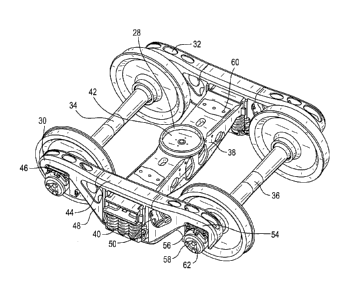
As shown in FIG. 1, a typical railway freight car truck 64 includes a pair of
side frames
30, 32 supported on axle-wheel sets 34, 36. Bolster 38 extends between and is
supported on
springs 40 mounted on side frames 30, 32. Bolster center plate 28 includes a
central opening 42.
Side bearing pads 60 are provided laterally to each side of the center plate
28 on bolster 38. Side
frames 30, 232 comprise a top member 44, compression member 46, tension member
48, column
50, pedestal 54, pedestal roof 56, wheel axle bearings 58, and bearing adapter
62. Side bearings
are commonly used on railroad car trucks. Such side bearings are typically
located on the truck
bolster such as on side bearing pads 60, but may be located elsewhere on the
bolster. Bolster 38
and side frames 30, 32 are usually unitary cast steel structures.
Typical side bearing arrangements are designed to control hunting of the
railroad car. As
a railroad car travels along the railroad track, a yaw excess motion can be
induced in the railroad
car truck. As the truck yaws, part of the side bearing is made to slide across
the underside of a
wear plate bolted to the railroad car body bolster. The resulting friction
produces an opposing
torque that acts to prevent such yaw motion. Another purpose of railroad car
truck side bearings
is control or limit the rock or roll motion of the car body. Most prior side
bearing designs limited
vertical travel of the side bearings.
Accordingly, it is an object of the present invention to provide an improved
side bearing
which will limit the vertical rock or roll motion of the railway freight car.
1

CA 02945287 2016-10-13
H8324176CA
It is another object of the present invention to provide an improved side
bearing which
will provide improved control over the rock or roll motion of an empty railway
freight car.
Summary of the Invention
A side bearing is provided with improved characteristics to enhance the
performance of
rail cars, especially in unloaded conditions.
One embodiment of a side bearing in accordance with the present invention
includes a
base structure. A leaf spring assembly is positioned on the base structure.
Shackles are affixed to
the ends of the base by pins. Leaf spring end clamps are connected to end
portions of the leaf
spring assembly. The shackles are also connected to the leaf spring end clamps
by pins. The pin
connections with the shackles allow rotation of the leaf spring assembly in
relation to the base
structure. A leaf spring top clamp assembly with a top clamp and a bottom
clamp joins a center
top portion of the leaf spring assembly. A top wear plate is fitted between
the leaf spring top
clamp and the top portion of the leaf spring assembly. The leaf spring
assembly has a
preselected non-compressed height.
The base is usually a unitary cast steel or cast iron or plate steel
structure. The leaf spring
itself is usually comprised of a glass fiber reinforced polymer but can be
comprised of a spring
steel. The shackles are usually formed of steel, either cast, machined or
stamped. The end and
top clamp assemblies are usually formed of a cast steel or steel bar, but also
in certain
embodiments could be fabricated. A bottom stop is also provided adjacent the
bottom of the top
clamp.
In usual embodiments, at the compressed standard set-up height of 5 1/16
inches, the top
of the leaf spring clamp will contact the support channel of the freight car
under normal
operating conditions for an empty and loaded railway car. In a rock condition
due to curving or
2

CA 02945287 2016-10-13
H8324176CA
other forces that the freight car is being subjected to, the leaf spring
assembly will be compressed
past the set-up height. Such leaf spring compression will limit the rock of
the railway freight car
to within design parameters.
Brief Description of the Drawings
In the drawings,
FIG. 1 is a perspective view of a typical railway freight car truck;
FIG. 2 is a top view of a leaf spring assembly side bearing in accordance with
an
embodiment of the present invention;
FIG. 3 is an end view of a leaf spring assembly side bearing in accordance
with an
embodiment of the present invention;
FIG. 4 is a perspective view of a leaf spring assembly side bearing in
accordance with an
embodiment of the present invention;
FIG. 5 is a side view of a leaf spring assembly side bearing in accordance
with an
embodiment of the present invention;
FIG. 6 is a perspective view of a typical railway freight car truck in
accordance with and
embodiment of the present invention.
Description of the Preferred Embodiment
Referring now to FIGS. 2- 6, a first embodiment of the leaf spring assembly
side bearing
according to the present invention is shown at 10. Side bearing assembly 10
includes a base
structure 1, which is comprised of a bottom portion 22 and end structures 24
extending vertically
upward from each end of bottom portion 22. Base structure 1 is usually cast
steel or cast iron
unitary structure, but can be a fabricated or machined steel plate as well,
with end structures 24
being unitary or welded or otherwise affixed to the ends of bottom portion 22.
The shape of
3

CA 02945287 2016-10-13
H8324176CA
bottom portion 22 can be somewhat rectangular, or somewhat oval or diamond
shaped as the use
dictates.
Bottom portion 22 of base 1 includes openings (not shown) that allow the ready

attachment of base 1 to side bearing pad 60 of bolster 38 by bolts or similar
devices.
Shackles 2 are used to connect base end structures 24 to leaf spring end
clamps 4 by the
use of pins 3. Leaf spring end clamps 4 are connected to the ends of leaf
springs 5 by similar
pins 3A. Shackles 2 can be cast, machined or stamped steel, and when combined
with pins 3 and
3A, allow leaf springs 5 to compress and flex as the load force from the
freight car is applied to
the leaf spring assembly side bearing 10.
Leaf springs 5 can be comprised of a mono-leaf spring or of multiple laminated
leaf
springs. Leaf spring 5 elements may be made of a glass fiber reinforced
polymer, or in certain
applications, spring steel.
Clamps 7 are used to hold the leaf spring together at the top of the leaf
springs. Clamps 7
are usually comprised of steel bar stock, which is held by bolts 7A or similar
devices. Top wear
plate 6 is positioned between clamp 7 and the top of leaf springs 5 to provide
improved wear
resistance between the bottom of the freight car support channel and leaf
spring 5. Top wear
plate 6 is usually made of a steel with a 10-15% manganese content.
Bottom stop 8 is placed at the bottom of clamp 7 to restrict the down travel
of leaf springs
5. Bottom stop 8 is usually made of cast or machined steel, and is affixed to
clamp 7 by bolts
7A. Bottom stop 8 is designed to limit the down travel of leaf springs 5 when
measured at clamp
7 to no more than 0.625 inch (1.58 cm). Such limitation in the down travel of
leaf spring 5
would limit the rock of the railway freight car.
4

Representative Drawing
A single figure which represents the drawing illustrating the invention.
Administrative Status

For a clearer understanding of the status of the application/patent presented on this page, the site Disclaimer , as well as the definitions for Patent , Administrative Status , Maintenance Fee  and Payment History  should be consulted.

Administrative Status

Title Date
Forecasted Issue Date 2018-11-20
(22) Filed 2016-10-13
Examination Requested 2016-10-13
(41) Open to Public Inspection 2017-04-22
(45) Issued 2018-11-20

Abandonment History

There is no abandonment history.

Maintenance Fee

Last Payment of $210.51 was received on 2023-09-20


 Upcoming maintenance fee amounts

Description Date Amount
Next Payment if standard fee 2024-10-15 $277.00
Next Payment if small entity fee 2024-10-15 $100.00

Note : If the full payment has not been received on or before the date indicated, a further fee may be required which may be one of the following

  • the reinstatement fee;
  • the late payment fee; or
  • additional fee to reverse deemed expiry.

Patent fees are adjusted on the 1st of January every year. The amounts above are the current amounts if received by December 31 of the current year.
Please refer to the CIPO Patent Fees web page to see all current fee amounts.

Payment History

Fee Type Anniversary Year Due Date Amount Paid Paid Date
Request for Examination $800.00 2016-10-13
Registration of a document - section 124 $100.00 2016-10-13
Application Fee $400.00 2016-10-13
Final Fee $300.00 2018-09-17
Maintenance Fee - Application - New Act 2 2018-10-15 $100.00 2018-10-11
Maintenance Fee - Patent - New Act 3 2019-10-15 $100.00 2019-09-20
Maintenance Fee - Patent - New Act 4 2020-10-13 $100.00 2020-09-17
Maintenance Fee - Patent - New Act 5 2021-10-13 $204.00 2021-09-21
Maintenance Fee - Patent - New Act 6 2022-10-13 $203.59 2022-09-22
Maintenance Fee - Patent - New Act 7 2023-10-13 $210.51 2023-09-20
Owners on Record

Note: Records showing the ownership history in alphabetical order.

Current Owners on Record
AMSTED RAIL COMPANY, INC.
Past Owners on Record
None
Past Owners that do not appear in the "Owners on Record" listing will appear in other documentation within the application.
Documents

To view selected files, please enter reCAPTCHA code :


To view images, click a link in the Document Description column. To download the documents, select one or more checkboxes in the first column and then click the "Download Selected in PDF format (Zip Archive)" or the "Download Selected as Single PDF" button.

List of published and non-published patent-specific documents on the CPD .

If you have any difficulty accessing content, you can call the Client Service Centre at 1-866-997-1936 or send them an e-mail at CIPO Client Service Centre.


Document
Description 
Date
(yyyy-mm-dd) 
Number of pages   Size of Image (KB) 
Claims 2016-10-13 3 63
Description 2016-10-13 4 165
Abstract 2016-10-13 1 12
Drawings 2016-10-13 4 125
Examiner Requisition 2017-10-17 3 192
Amendment 2018-04-09 5 145
Claims 2018-04-09 3 66
Drawings 2018-04-09 4 126
Final Fee 2018-09-17 1 43
Cover Page 2018-10-25 1 59
New Application 2016-10-13 5 123
Representative Drawing 2017-03-20 1 24
Cover Page 2017-03-20 2 56