Sélection de la langue

Search

Sommaire du brevet 2945287 

Énoncé de désistement de responsabilité concernant l'information provenant de tiers

Une partie des informations de ce site Web a été fournie par des sources externes. Le gouvernement du Canada n'assume aucune responsabilité concernant la précision, l'actualité ou la fiabilité des informations fournies par les sources externes. Les utilisateurs qui désirent employer cette information devraient consulter directement la source des informations. Le contenu fourni par les sources externes n'est pas assujetti aux exigences sur les langues officielles, la protection des renseignements personnels et l'accessibilité.

Disponibilité de l'Abrégé et des Revendications

L'apparition de différences dans le texte et l'image des Revendications et de l'Abrégé dépend du moment auquel le document est publié. Les textes des Revendications et de l'Abrégé sont affichés :

  • lorsque la demande peut être examinée par le public;
  • lorsque le brevet est émis (délivrance).
(12) Brevet: (11) CA 2945287
(54) Titre français: PALIER LATERAL DESTINE A UN WAGON-BOGIE
(54) Titre anglais: SIDE BEARING FOR RAILWAY CAR TRUCK
Statut: Octroyé
Données bibliographiques
(51) Classification internationale des brevets (CIB):
  • B61F 5/14 (2006.01)
(72) Inventeurs :
  • WIKE, PAUL (Etats-Unis d'Amérique)
  • HARRIS, ZACHARY (Etats-Unis d'Amérique)
(73) Titulaires :
  • AMSTED RAIL COMPANY, INC. (Etats-Unis d'Amérique)
(71) Demandeurs :
  • AMSTED RAIL COMPANY, INC. (Etats-Unis d'Amérique)
(74) Agent: GOWLING WLG (CANADA) LLP
(74) Co-agent:
(45) Délivré: 2018-11-20
(22) Date de dépôt: 2016-10-13
(41) Mise à la disponibilité du public: 2017-04-22
Requête d'examen: 2016-10-13
Licence disponible: S.O.
(25) Langue des documents déposés: Anglais

Traité de coopération en matière de brevets (PCT): Non

(30) Données de priorité de la demande:
Numéro de la demande Pays / territoire Date
14/920,171 Etats-Unis d'Amérique 2015-10-22

Abrégés

Abrégé français

Un assemblage de palier latéral à ressort à lames destiné à des wagons de marchandise est présenté qui réaliser un suivi et une courbe améliorés en limitant le basculement du wagon de marchandise. Le palier latéral comprend une base dotée de deux sections dextrémité surélevées. Un assemblage de ressort à lames est présent sur la base qui se prolonge vers le dessous et supporte un canal du wagon de marchandise. Une plaque dusure supérieure et une butée de parcours inférieure sont également incluses dans lassemblage de palier latéral à ressort à lames.


Abrégé anglais

An improved leaf spring side bearing assembly for railway freight cars is provided that achieves improved tracking and curving by the limitation of rock of the railway freight car. The side bearing comprises a base with two raised end sections. A leaf spring assembly is provided on the base that extends to the underside and support channel of the freight car. A top wear plate and a bottom travel stop are also included with the leaf spring side bearing assembly.

Revendications

Note : Les revendications sont présentées dans la langue officielle dans laquelle elles ont été soumises.


What is claimed is:
1. A side bearing assembly comprising:
a base structure having two ends,
four shackles, each shackle connected to one of the base structure ends,
a leaf spring assembly having two ends,
two leaf spring end clamps, each leaf spring end clamp connected to each end
of the leaf
spring assembly,
each leaf spring end clamp also connected to two of the shackles,
a top clamp joining a top portion of the leaf spring assembly,
and a bottom stop connected to a bottom of the top clamp.
2. The side bearing assembly of claim 1 further comprising
a wear plate positioned between the top portion of the leaf spring assembly
and the
clamp.
3. The side bearing assembly of claim 1 further comprising
a first pin joining the shackle to the base structure end in a manner to allow
rotation
between the shackle and the base structure end.
4. The side bearing assembly of claim 1 further comprising

a second pin joining the shackle to the leaf spring end clamp in a manner to
allow
rotation between the shackle and the leaf spring end clamp.
5. The side bearing assembly of claim 1 wherein the maximum travel of the leaf
spring
assembly downward from an unloaded position is less than 0.625 inch.
6. The side bearing assembly of claim 1 wherein the leaf spring assembly is
comprised
of a glass fiber reinforced polymer leaf spring.
7. A side bearing assembly comprising:
a base structure having two ends,
a plurality of shackles, each shackle connected to one of the base structure
ends,
a leaf spring having two ends and a top portion,
two leaf spring end clamps, with each leaf spring end clamp connected to one
end of the
leaf spring,
each leaf spring end clamp also connected to two of the shackles,
a top clamp joining the top portion of the leaf spring,
and a bottom stop connected to a bottom of the top clamp.
8. The side bearing assembly of claim 7 further comprising
a wear plate positioned between the top portion of the leaf spring and the top
clamp.
9. The side bearing assembly of claim 7 further comprising
6

a first pin joining the shackle to the base structure end in a manner to allow
rotation
between the shackle and the base structure end.
10. The side bearing assembly of claim 7 further comprising
a second pin joining the shackle to the leaf spring end clamp in a manner to
allow
rotation between the shackle and the leaf spring end clamp.
11. The side bearing assembly of claim 7 wherein the maximum travel of the top
portion
of the leaf spring downward from an unloaded position is less than 0.625 inch.
12. The side bearing assembly of claim 7 wherein the leaf spring is comprised
of a glass
fiber reinforced polymer leaf spring.

7

Description

Note : Les descriptions sont présentées dans la langue officielle dans laquelle elles ont été soumises.

CA 02945287 2016-10-13
H8324176CA
Side Bearing for Railway Car Truck
Background of the Invention
The present invention relates to an improved side bearing for mounting on a
railway car
truck bolster that provides improved control to limit rock and roll
characteristics of the railway
car in service.
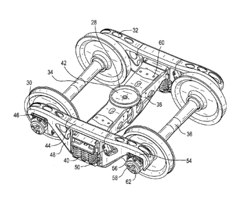
As shown in FIG. 1, a typical railway freight car truck 64 includes a pair of
side frames
30, 32 supported on axle-wheel sets 34, 36. Bolster 38 extends between and is
supported on
springs 40 mounted on side frames 30, 32. Bolster center plate 28 includes a
central opening 42.
Side bearing pads 60 are provided laterally to each side of the center plate
28 on bolster 38. Side
frames 30, 232 comprise a top member 44, compression member 46, tension member
48, column
50, pedestal 54, pedestal roof 56, wheel axle bearings 58, and bearing adapter
62. Side bearings
are commonly used on railroad car trucks. Such side bearings are typically
located on the truck
bolster such as on side bearing pads 60, but may be located elsewhere on the
bolster. Bolster 38
and side frames 30, 32 are usually unitary cast steel structures.
Typical side bearing arrangements are designed to control hunting of the
railroad car. As
a railroad car travels along the railroad track, a yaw excess motion can be
induced in the railroad
car truck. As the truck yaws, part of the side bearing is made to slide across
the underside of a
wear plate bolted to the railroad car body bolster. The resulting friction
produces an opposing
torque that acts to prevent such yaw motion. Another purpose of railroad car
truck side bearings
is control or limit the rock or roll motion of the car body. Most prior side
bearing designs limited
vertical travel of the side bearings.
Accordingly, it is an object of the present invention to provide an improved
side bearing
which will limit the vertical rock or roll motion of the railway freight car.
1

CA 02945287 2016-10-13
H8324176CA
It is another object of the present invention to provide an improved side
bearing which
will provide improved control over the rock or roll motion of an empty railway
freight car.
Summary of the Invention
A side bearing is provided with improved characteristics to enhance the
performance of
rail cars, especially in unloaded conditions.
One embodiment of a side bearing in accordance with the present invention
includes a
base structure. A leaf spring assembly is positioned on the base structure.
Shackles are affixed to
the ends of the base by pins. Leaf spring end clamps are connected to end
portions of the leaf
spring assembly. The shackles are also connected to the leaf spring end clamps
by pins. The pin
connections with the shackles allow rotation of the leaf spring assembly in
relation to the base
structure. A leaf spring top clamp assembly with a top clamp and a bottom
clamp joins a center
top portion of the leaf spring assembly. A top wear plate is fitted between
the leaf spring top
clamp and the top portion of the leaf spring assembly. The leaf spring
assembly has a
preselected non-compressed height.
The base is usually a unitary cast steel or cast iron or plate steel
structure. The leaf spring
itself is usually comprised of a glass fiber reinforced polymer but can be
comprised of a spring
steel. The shackles are usually formed of steel, either cast, machined or
stamped. The end and
top clamp assemblies are usually formed of a cast steel or steel bar, but also
in certain
embodiments could be fabricated. A bottom stop is also provided adjacent the
bottom of the top
clamp.
In usual embodiments, at the compressed standard set-up height of 5 1/16
inches, the top
of the leaf spring clamp will contact the support channel of the freight car
under normal
operating conditions for an empty and loaded railway car. In a rock condition
due to curving or
2

CA 02945287 2016-10-13
H8324176CA
other forces that the freight car is being subjected to, the leaf spring
assembly will be compressed
past the set-up height. Such leaf spring compression will limit the rock of
the railway freight car
to within design parameters.
Brief Description of the Drawings
In the drawings,
FIG. 1 is a perspective view of a typical railway freight car truck;
FIG. 2 is a top view of a leaf spring assembly side bearing in accordance with
an
embodiment of the present invention;
FIG. 3 is an end view of a leaf spring assembly side bearing in accordance
with an
embodiment of the present invention;
FIG. 4 is a perspective view of a leaf spring assembly side bearing in
accordance with an
embodiment of the present invention;
FIG. 5 is a side view of a leaf spring assembly side bearing in accordance
with an
embodiment of the present invention;
FIG. 6 is a perspective view of a typical railway freight car truck in
accordance with and
embodiment of the present invention.
Description of the Preferred Embodiment
Referring now to FIGS. 2- 6, a first embodiment of the leaf spring assembly
side bearing
according to the present invention is shown at 10. Side bearing assembly 10
includes a base
structure 1, which is comprised of a bottom portion 22 and end structures 24
extending vertically
upward from each end of bottom portion 22. Base structure 1 is usually cast
steel or cast iron
unitary structure, but can be a fabricated or machined steel plate as well,
with end structures 24
being unitary or welded or otherwise affixed to the ends of bottom portion 22.
The shape of
3

CA 02945287 2016-10-13
H8324176CA
bottom portion 22 can be somewhat rectangular, or somewhat oval or diamond
shaped as the use
dictates.
Bottom portion 22 of base 1 includes openings (not shown) that allow the ready

attachment of base 1 to side bearing pad 60 of bolster 38 by bolts or similar
devices.
Shackles 2 are used to connect base end structures 24 to leaf spring end
clamps 4 by the
use of pins 3. Leaf spring end clamps 4 are connected to the ends of leaf
springs 5 by similar
pins 3A. Shackles 2 can be cast, machined or stamped steel, and when combined
with pins 3 and
3A, allow leaf springs 5 to compress and flex as the load force from the
freight car is applied to
the leaf spring assembly side bearing 10.
Leaf springs 5 can be comprised of a mono-leaf spring or of multiple laminated
leaf
springs. Leaf spring 5 elements may be made of a glass fiber reinforced
polymer, or in certain
applications, spring steel.
Clamps 7 are used to hold the leaf spring together at the top of the leaf
springs. Clamps 7
are usually comprised of steel bar stock, which is held by bolts 7A or similar
devices. Top wear
plate 6 is positioned between clamp 7 and the top of leaf springs 5 to provide
improved wear
resistance between the bottom of the freight car support channel and leaf
spring 5. Top wear
plate 6 is usually made of a steel with a 10-15% manganese content.
Bottom stop 8 is placed at the bottom of clamp 7 to restrict the down travel
of leaf springs
5. Bottom stop 8 is usually made of cast or machined steel, and is affixed to
clamp 7 by bolts
7A. Bottom stop 8 is designed to limit the down travel of leaf springs 5 when
measured at clamp
7 to no more than 0.625 inch (1.58 cm). Such limitation in the down travel of
leaf spring 5
would limit the rock of the railway freight car.
4

Dessin représentatif
Une figure unique qui représente un dessin illustrant l'invention.
États administratifs

Pour une meilleure compréhension de l'état de la demande ou brevet qui figure sur cette page, la rubrique Mise en garde , et les descriptions de Brevet , États administratifs , Taxes périodiques et Historique des paiements devraient être consultées.

États administratifs

Titre Date
Date de délivrance prévu 2018-11-20
(22) Dépôt 2016-10-13
Requête d'examen 2016-10-13
(41) Mise à la disponibilité du public 2017-04-22
(45) Délivré 2018-11-20

Historique d'abandonnement

Il n'y a pas d'historique d'abandonnement

Taxes périodiques

Dernier paiement au montant de 210,51 $ a été reçu le 2023-09-20


 Montants des taxes pour le maintien en état à venir

Description Date Montant
Prochain paiement si taxe générale 2024-10-15 277,00 $
Prochain paiement si taxe applicable aux petites entités 2024-10-15 100,00 $

Avis : Si le paiement en totalité n'a pas été reçu au plus tard à la date indiquée, une taxe supplémentaire peut être imposée, soit une des taxes suivantes :

  • taxe de rétablissement ;
  • taxe pour paiement en souffrance ; ou
  • taxe additionnelle pour le renversement d'une péremption réputée.

Les taxes sur les brevets sont ajustées au 1er janvier de chaque année. Les montants ci-dessus sont les montants actuels s'ils sont reçus au plus tard le 31 décembre de l'année en cours.
Veuillez vous référer à la page web des taxes sur les brevets de l'OPIC pour voir tous les montants actuels des taxes.

Historique des paiements

Type de taxes Anniversaire Échéance Montant payé Date payée
Requête d'examen 800,00 $ 2016-10-13
Enregistrement de documents 100,00 $ 2016-10-13
Le dépôt d'une demande de brevet 400,00 $ 2016-10-13
Taxe finale 300,00 $ 2018-09-17
Taxe de maintien en état - Demande - nouvelle loi 2 2018-10-15 100,00 $ 2018-10-11
Taxe de maintien en état - brevet - nouvelle loi 3 2019-10-15 100,00 $ 2019-09-20
Taxe de maintien en état - brevet - nouvelle loi 4 2020-10-13 100,00 $ 2020-09-17
Taxe de maintien en état - brevet - nouvelle loi 5 2021-10-13 204,00 $ 2021-09-21
Taxe de maintien en état - brevet - nouvelle loi 6 2022-10-13 203,59 $ 2022-09-22
Taxe de maintien en état - brevet - nouvelle loi 7 2023-10-13 210,51 $ 2023-09-20
Titulaires au dossier

Les titulaires actuels et antérieures au dossier sont affichés en ordre alphabétique.

Titulaires actuels au dossier
AMSTED RAIL COMPANY, INC.
Titulaires antérieures au dossier
S.O.
Les propriétaires antérieurs qui ne figurent pas dans la liste des « Propriétaires au dossier » apparaîtront dans d'autres documents au dossier.
Documents

Pour visionner les fichiers sélectionnés, entrer le code reCAPTCHA :


Pour visualiser une image, cliquer sur un lien dans la colonne description du document. Pour télécharger l'image (les images), cliquer l'une ou plusieurs cases à cocher dans la première colonne et ensuite cliquer sur le bouton "Télécharger sélection en format PDF (archive Zip)" ou le bouton "Télécharger sélection (en un fichier PDF fusionné)".

Liste des documents de brevet publiés et non publiés sur la BDBC .

Si vous avez des difficultés à accéder au contenu, veuillez communiquer avec le Centre de services à la clientèle au 1-866-997-1936, ou envoyer un courriel au Centre de service à la clientèle de l'OPIC.


Description du
Document 
Date
(yyyy-mm-dd) 
Nombre de pages   Taille de l'image (Ko) 
Revendications 2016-10-13 3 63
Description 2016-10-13 4 165
Abrégé 2016-10-13 1 12
Dessins 2016-10-13 4 125
Demande d'examen 2017-10-17 3 192
Modification 2018-04-09 5 145
Revendications 2018-04-09 3 66
Dessins 2018-04-09 4 126
Taxe finale 2018-09-17 1 43
Page couverture 2018-10-25 1 59
Nouvelle demande 2016-10-13 5 123
Dessins représentatifs 2017-03-20 1 24
Page couverture 2017-03-20 2 56