Language selection

Search

Patent 2948522 Summary

Third-party information liability

Some of the information on this Web page has been provided by external sources. The Government of Canada is not responsible for the accuracy, reliability or currency of the information supplied by external sources. Users wishing to rely upon this information should consult directly with the source of the information. Content provided by external sources is not subject to official languages, privacy and accessibility requirements.

Claims and Abstract availability

Any discrepancies in the text and image of the Claims and Abstract are due to differing posting times. Text of the Claims and Abstract are posted:

  • At the time the application is open to public inspection;
  • At the time of issue of the patent (grant).
(12) Patent: (11) CA 2948522
(54) English Title: POLE AND HUB
(54) French Title: POTEAU ET MOYEU
Status: Granted
Bibliographic Data
(51) International Patent Classification (IPC):
  • A01K 39/01 (2006.01)
  • A45F 3/44 (2006.01)
  • E04H 12/00 (2006.01)
  • F16M 13/00 (2006.01)
(72) Inventors :
  • COTE, PAUL L. (Canada)
(73) Owners :
  • BROME BIRD CARE INC. (Canada)
(71) Applicants :
  • COTE, PAUL L. (Canada)
(74) Agent:
(74) Associate agent:
(45) Issued: 2019-07-30
(22) Filed Date: 2016-11-14
(41) Open to Public Inspection: 2017-05-13
Examination requested: 2019-03-25
Availability of licence: N/A
(25) Language of filing: English

Patent Cooperation Treaty (PCT): No

(30) Application Priority Data:
Application No. Country/Territory Date
2,911,981 Canada 2015-11-13

Abstracts

English Abstract

There is provided a pole system suitable for supporting other objects such as bird feeders, plants and the like, the pole system having a pole with at least one transversely extending aperture formed therein, a pin mounted in the aperture and extending exteriorly of the pole on opposite sides thereof, and a hub member having a bottom surface, the bottom surface including a scalloped wall which is arranged to receive the pin such that the hub member is supported, the scalloped wall permitting rotation of the hub when sufficient rotational force is applied thereto.


French Abstract

Un système de poteau est présenté convenable pour supporter dautres objets comme des mangeoires à oiseaux, des plantes et autres semblables, le système de poteau comportant un poteau ayant une ouverture formée intégralement se prolongeant transversalement, une tige installée dans louverture et se prolongeant extérieurement par rapport au poteau sur ses côtés opposés et un élément de moyeu ayant une surface de fond, la surface de fond comprenant une paroi festonnée qui est arrangée pour recevoir la tige de sorte que lélément de moyeu est supporté, la paroi festonnée permettant la rotation du moyeu quand une force rotative suffisante est exercée.

Claims

Note: Claims are shown in the official language in which they were submitted.

The embodiments of an invention in which an exclusive property or privilege is

claimed is defined as follows:
1. A pole system comprising:
a pole having at least one transversely extending aperture formed therein,
said aperture
extending through said pole;
a pin mounted in said aperture, said pin extending exteriorly of said pole on
opposite
sides thereof; and
a hub member rotatably mounted on the pole, said hub member having a bottom
surface,
said bottom surface including a scalloped wall, said scalloped wall sitting on
said pin such that
said hub member is supported, said scalloped wall comprising a plurality of
arcuate recesses so
as to permit rotation of said hub about said pole when a sufficiently large
rotational force is
applied to said hub, said hub member further including an outer wall, said
scalloped wall being
located interiorly of said outer wall, said outer wall extending downwardly
about said pin to
thereby prevent removal of said pin.
2. The pole system of claim 1 further including a plurality of apertures
extending through
said pole.
3. The pole system of claim 1 further including a container, said container
being supported
by said hub member.
4. The pole system of claim 1 wherein said hub member includes a plurality
of vertically
extending inner channels, a plurality of supporting members each including a
vertical segment,
each of said vertical segments being designed to fit within a corresponding
vertically extending
inner channel.
-7-

5. The
pole system of claim 4 wherein each of said supporting members is arranged to
receive a container.
-8-

Description

Note: Descriptions are shown in the official language in which they were submitted.


CA 02948522 2016-11-14
POLE AND HUB
FIELD OF THE INVENTION
The present invention relates to pole systems, and more particularly, relates
to
improvements in pole systems.
BACKGROUND OF THE INVENTION
Pole systems have been known in the art for many years. Pole systems basically
comprise a pole which may be implanted in the ground or other medium, or
alternatively,
which may be secured to an adjacent structure. The pole is then used to
support one or more
members or structures thereon. Such structures can include, for example,
horticultural
containers, bird feeders, etc.
A pole system which is implanted in the ground is essentially a relatively
fragile
structure. The poles are easily dislocated from the medium in which they are
implanted and
generally cannot support a very large weight, particularly unbalanced weight.
Such
unbalanced weight will tend to exert a force on the pole which will cause the
same to lean or
fall.
SUMMARY OF THE INVENTION
It is an object of the present invention to provide a pole system which has
sufficient
rigidity and strength to be implanted in the ground and which can serve a
multitude of uses.
According to one aspect of the present invention, there is provided a pole
system
comprising a pole having at least one transversely extending aperture formed
therein, the
aperture extending through the pole, a pin mounted in the aperture, the pin
extending
exteriorly of the pole on opposite sides thereof, and a hub member, the hub
member having a
- 1 -

CA 02948522 2016-11-14
bottom surface, the bottom surface including a scalloped wall, the scalloped
wall sitting on
the pin such that the hub member is supported.
The hub member, as stated above, has a wall with a scalloped surface. The wall

having the scalloped surface functions as a support for the hub in that the
pin mounted
within the aperture in the pole rests on the hub member and more particularly,
rests on the
scalloped wall. As there are a plurality of scallops formed in the wall, a
rotational force
applied to the hub will be resisted to the extent that the force will cause
the hub to rotate and
cause the pin to move into an adjacent scallop.
Each scallop is defined as an arcuate recess formed in the bottom wall of the
hub
member. Each arcuate recess is formed by first and second diagonally extending
walls
which have a seat formed at their point of juncture. Each seat is arcuate in
configuration and
is designed to receive the supporting pin mounted in the aperture of the pole.
The pole will include a plurality of apertures formed therein such that pins
may be
inserted at various locations. Each pin is designed to support a hub or hub
like member. In
the case of a hub, the hub is arranged to receive supporting members which are
inserted
therein. The supporting members will include a vertical segment which fits
within the hub
and an outwardly extending arm. The outwardly extending arm may in turn
support other
desired objects. Such objects could include bird feeders, trays and the like.
Each hub may also function to support a container which is integrated with the
hub.
Such containers could include plant containers, feeders, etc.
The hub may be formed of any suitable material and in a preferred embodiment,
is
formed of a plastic material. Many such plastic materials are known in the art
and can be
- 2 -

CA 02948522 2016-11-14
utilized in the practice of the present invention.
BRIEF DESCRIPTION OF THE DRAWINGS
Having thus generally described the invention, reference will be made to the
accompanying drawings illustrating an embodiment thereof, in which:
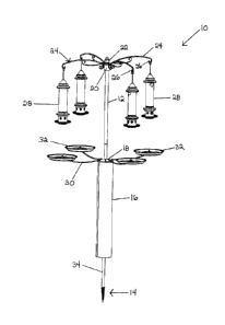
Figure 1 is perspective view of a first embodiment of the invention;
Figure 2 is a perspective view of a further embodiment of the present
invention;
Figure 3 is a perspective of a still further embodiment of the present
invention;
Figure 4 is a cross-sectional view illustrating the hub member of the present
invention;
Figure 5 is a perspective view of the bottom of a hub according to the present

invention;
Figure 6 is an exploded view of an embodiment of the present invention;
Figure 7 is a perspective view illustrating the bottom of the inner and outer
walls
forming a hub member; and
Figure 8 is a partial perspective view of the hub member.
DETAILED DESCRIPTION OF THE INVENTION
Referring to the drawings in greater detail and by reference characters
thereto, there
is illustrated in Figure 1 a first embodiment of the present invention wherein
there is shown
a pole system generally designated by reference numeral 10.
Pole system 10 includes a pole 12 which, in some embodiments, may be formed of
a
plurality of components suitably secured together. As seen, pole 12 includes a

screwthreaded end segment 14. Screwthreaded end system 14 is preferably formed
to have
- 3 -

CA 02948522 2016-11-14
a double helical screw on the outside thereof. The double helical screw
preferably includes
a first thread which extends outwardly from the base by a first distance, and
a second thread
which extends outwardly from the base by a second distance, with the first
distance being
greater than the second distance.
As may be seen in Figure 1, the lower portion of pole 12 is surrounded by a
baffle 16
in order to deny access to animals attempting to climb the pole system. Both
pole 12 and
baffle 16 may be formed of any suitable material and in the preferred
embodiment, are
formed of a metallic material.
In the embodiment illustrated in Figure 1, pole system 10 includes a lower hub
18 and
an upper hub 20 which will be described in greater detail hereinbelow.
The top of the pole is capped with a finial 22.
Upper hub 20 has a plurality of upper supporting members 24 mounted therein as
will
be discussed in greater detail hereinbelow. Each upper supporting member 24
has a curled
end forming a hook 26. Mounted on upper supporting members 24 are bird feeders

generally designated by reference numeral 28. Each bird feeder 28 may be any
suitable type
known in the art.
Lower hub 18 also supports lower supporting members 30 which extend outwardly
therefrom. Each lower supporting member 30 has a tray 32 associated therewith.
Trays 32
are mounted so as to be below a respective bird feeder 28. When feeding from
bird
feeders 28, certain birds discard a number of seeds. These stray seeds can
kill vegetation
located below the bird feeder. In the present case, each tray 32 will catch
the excess seed
and other birds may eat the same.
- 4 -

CA 02948522 2016-11-14
Pole 12 includes a plurality of apertures 34 formed therein. Pole apertures 34
are
designed to receive a member to allow the support of hubs 18, 20.
Turning to the embodiment of Figure 2, there is illustrated a modification of
the pole
system of Figure 1. In the arrangement of Figure 2, there is provided an
intermediate hub
and container generally designated by reference numeral 36. There is also
provided a lower
hub and a container generally designated by reference numeral 38.
Turning to Figure 3, there is illustrated a pole system wherein pole 12 is
comprised of
a plurality of pole sections 42. In lieu of a threaded end segment, there is
provided a
base 44 for support of pole sections 42.
Figures 4 to 8 illustrate a hub member 20. Hub member 20 is formed to have an
outer wall 48 and an inner wall 50. Inner wall 50 has a scalloped bottom wall
52.
Scalloped bottom wall 52 comprises a plurality of arcuate recesses 54. Each
arcuate recess
is defined by a first sloping wall 56 and a second sloping wall 58 which meet
at an arcuate
seat 60. Extending between outer wall 48 and inner wall 50 are a plurality of
transverse
walls 62 which define a plurality of inner channels. The inner channels are
designed to
receive supporting members 24. Each supporting member 24 includes a vertical
segment 64
designed to fit within one of the channels. Connecting with vertical segment
64 is an
outwardly extending support arm 66 which in turn has a downwardly extending
segment 68
which reinforces support arm 66 and also provides an abutting portion against
outer wall 48.
As may be seen in the drawings, a support pin 70 extends through an aperture
34 in pole 12
and is designed to fit within arcuate recess 54.
The arrangement is such that support pin 70 can ride up one of the sloping
walls 56 to
- 5 -

CA 02948522 2016-11-14
seat within an adjacent arcuate recess 54 if sufficient force is applied to
hub 20. Such may
be the case, for example, when exterior forces such as wind and/or a person
knocking one of
the arms supplies such a force.
As seen in Figures 5 and 6, a projection 78 is formed on outer wall 48 where
downwardly extending segment 68 abuts the outer wall 48. A slot 80 is formed
in the upper
marginal edge of outer wall 48 to receive support arm 66.
- 6 -

Representative Drawing
A single figure which represents the drawing illustrating the invention.
Administrative Status

For a clearer understanding of the status of the application/patent presented on this page, the site Disclaimer , as well as the definitions for Patent , Administrative Status , Maintenance Fee  and Payment History  should be consulted.

Administrative Status

Title Date
Forecasted Issue Date 2019-07-30
(22) Filed 2016-11-14
(41) Open to Public Inspection 2017-05-13
Examination Requested 2019-03-25
(45) Issued 2019-07-30

Abandonment History

There is no abandonment history.

Maintenance Fee

Last Payment of $100.00 was received on 2023-11-08


 Upcoming maintenance fee amounts

Description Date Amount
Next Payment if standard fee 2024-11-14 $277.00
Next Payment if small entity fee 2024-11-14 $100.00

Note : If the full payment has not been received on or before the date indicated, a further fee may be required which may be one of the following

  • the reinstatement fee;
  • the late payment fee; or
  • additional fee to reverse deemed expiry.

Patent fees are adjusted on the 1st of January every year. The amounts above are the current amounts if received by December 31 of the current year.
Please refer to the CIPO Patent Fees web page to see all current fee amounts.

Payment History

Fee Type Anniversary Year Due Date Amount Paid Paid Date
Application Fee $200.00 2016-11-14
Maintenance Fee - Application - New Act 2 2018-11-14 $50.00 2018-10-16
Request for Examination $400.00 2019-03-25
Final Fee $150.00 2019-06-12
Maintenance Fee - Patent - New Act 3 2019-11-14 $50.00 2019-11-05
Maintenance Fee - Patent - New Act 4 2020-11-16 $50.00 2020-11-12
Registration of a document - section 124 $100.00 2021-03-25
Maintenance Fee - Patent - New Act 5 2021-11-15 $100.00 2021-11-12
Maintenance Fee - Patent - New Act 6 2022-11-14 $100.00 2022-11-14
Maintenance Fee - Patent - New Act 7 2023-11-14 $100.00 2023-11-08
Owners on Record

Note: Records showing the ownership history in alphabetical order.

Current Owners on Record
BROME BIRD CARE INC.
Past Owners on Record
COTE, PAUL L.
Past Owners that do not appear in the "Owners on Record" listing will appear in other documentation within the application.
Documents

To view selected files, please enter reCAPTCHA code :


To view images, click a link in the Document Description column. To download the documents, select one or more checkboxes in the first column and then click the "Download Selected in PDF format (Zip Archive)" or the "Download Selected as Single PDF" button.

List of published and non-published patent-specific documents on the CPD .

If you have any difficulty accessing content, you can call the Client Service Centre at 1-866-997-1936 or send them an e-mail at CIPO Client Service Centre.


Document
Description 
Date
(yyyy-mm-dd) 
Number of pages   Size of Image (KB) 
Change to the Method of Correspondence 2021-03-25 5 152
Office Letter 2021-05-26 2 199
Maintenance Fee Payment 2022-11-14 1 33
Abstract 2016-11-14 1 15
Description 2016-11-14 6 211
Claims 2016-11-14 1 30
Drawings 2016-11-14 8 134
PPH OEE 2019-03-25 3 178
PPH Request 2019-03-25 6 200
Claims 2019-03-25 2 42
Final Fee 2019-06-12 1 31
Cover Page 2019-07-03 1 31
New Application 2016-11-14 2 67
Representative Drawing 2017-04-11 1 5
Cover Page 2017-04-11 2 35