Sélection de la langue

Search

Sommaire du brevet 2948522 

Énoncé de désistement de responsabilité concernant l'information provenant de tiers

Une partie des informations de ce site Web a été fournie par des sources externes. Le gouvernement du Canada n'assume aucune responsabilité concernant la précision, l'actualité ou la fiabilité des informations fournies par les sources externes. Les utilisateurs qui désirent employer cette information devraient consulter directement la source des informations. Le contenu fourni par les sources externes n'est pas assujetti aux exigences sur les langues officielles, la protection des renseignements personnels et l'accessibilité.

Disponibilité de l'Abrégé et des Revendications

L'apparition de différences dans le texte et l'image des Revendications et de l'Abrégé dépend du moment auquel le document est publié. Les textes des Revendications et de l'Abrégé sont affichés :

  • lorsque la demande peut être examinée par le public;
  • lorsque le brevet est émis (délivrance).
(12) Brevet: (11) CA 2948522
(54) Titre français: POTEAU ET MOYEU
(54) Titre anglais: POLE AND HUB
Statut: Octroyé
Données bibliographiques
(51) Classification internationale des brevets (CIB):
  • A01K 39/01 (2006.01)
  • A45F 3/44 (2006.01)
  • E04H 12/00 (2006.01)
  • F16M 13/00 (2006.01)
(72) Inventeurs :
  • COTE, PAUL L. (Canada)
(73) Titulaires :
  • BROME BIRD CARE INC. (Canada)
(71) Demandeurs :
  • COTE, PAUL L. (Canada)
(74) Agent:
(74) Co-agent:
(45) Délivré: 2019-07-30
(22) Date de dépôt: 2016-11-14
(41) Mise à la disponibilité du public: 2017-05-13
Requête d'examen: 2019-03-25
Licence disponible: S.O.
(25) Langue des documents déposés: Anglais

Traité de coopération en matière de brevets (PCT): Non

(30) Données de priorité de la demande:
Numéro de la demande Pays / territoire Date
2,911,981 Canada 2015-11-13

Abrégés

Abrégé français

Un système de poteau est présenté convenable pour supporter dautres objets comme des mangeoires à oiseaux, des plantes et autres semblables, le système de poteau comportant un poteau ayant une ouverture formée intégralement se prolongeant transversalement, une tige installée dans louverture et se prolongeant extérieurement par rapport au poteau sur ses côtés opposés et un élément de moyeu ayant une surface de fond, la surface de fond comprenant une paroi festonnée qui est arrangée pour recevoir la tige de sorte que lélément de moyeu est supporté, la paroi festonnée permettant la rotation du moyeu quand une force rotative suffisante est exercée.


Abrégé anglais

There is provided a pole system suitable for supporting other objects such as bird feeders, plants and the like, the pole system having a pole with at least one transversely extending aperture formed therein, a pin mounted in the aperture and extending exteriorly of the pole on opposite sides thereof, and a hub member having a bottom surface, the bottom surface including a scalloped wall which is arranged to receive the pin such that the hub member is supported, the scalloped wall permitting rotation of the hub when sufficient rotational force is applied thereto.

Revendications

Note : Les revendications sont présentées dans la langue officielle dans laquelle elles ont été soumises.


The embodiments of an invention in which an exclusive property or privilege is

claimed is defined as follows:
1. A pole system comprising:
a pole having at least one transversely extending aperture formed therein,
said aperture
extending through said pole;
a pin mounted in said aperture, said pin extending exteriorly of said pole on
opposite
sides thereof; and
a hub member rotatably mounted on the pole, said hub member having a bottom
surface,
said bottom surface including a scalloped wall, said scalloped wall sitting on
said pin such that
said hub member is supported, said scalloped wall comprising a plurality of
arcuate recesses so
as to permit rotation of said hub about said pole when a sufficiently large
rotational force is
applied to said hub, said hub member further including an outer wall, said
scalloped wall being
located interiorly of said outer wall, said outer wall extending downwardly
about said pin to
thereby prevent removal of said pin.
2. The pole system of claim 1 further including a plurality of apertures
extending through
said pole.
3. The pole system of claim 1 further including a container, said container
being supported
by said hub member.
4. The pole system of claim 1 wherein said hub member includes a plurality
of vertically
extending inner channels, a plurality of supporting members each including a
vertical segment,
each of said vertical segments being designed to fit within a corresponding
vertically extending
inner channel.
-7-

5. The
pole system of claim 4 wherein each of said supporting members is arranged to
receive a container.
-8-

Description

Note : Les descriptions sont présentées dans la langue officielle dans laquelle elles ont été soumises.

CA 02948522 2016-11-14
POLE AND HUB
FIELD OF THE INVENTION
The present invention relates to pole systems, and more particularly, relates
to
improvements in pole systems.
BACKGROUND OF THE INVENTION
Pole systems have been known in the art for many years. Pole systems basically
comprise a pole which may be implanted in the ground or other medium, or
alternatively,
which may be secured to an adjacent structure. The pole is then used to
support one or more
members or structures thereon. Such structures can include, for example,
horticultural
containers, bird feeders, etc.
A pole system which is implanted in the ground is essentially a relatively
fragile
structure. The poles are easily dislocated from the medium in which they are
implanted and
generally cannot support a very large weight, particularly unbalanced weight.
Such
unbalanced weight will tend to exert a force on the pole which will cause the
same to lean or
fall.
SUMMARY OF THE INVENTION
It is an object of the present invention to provide a pole system which has
sufficient
rigidity and strength to be implanted in the ground and which can serve a
multitude of uses.
According to one aspect of the present invention, there is provided a pole
system
comprising a pole having at least one transversely extending aperture formed
therein, the
aperture extending through the pole, a pin mounted in the aperture, the pin
extending
exteriorly of the pole on opposite sides thereof, and a hub member, the hub
member having a
- 1 -

CA 02948522 2016-11-14
bottom surface, the bottom surface including a scalloped wall, the scalloped
wall sitting on
the pin such that the hub member is supported.
The hub member, as stated above, has a wall with a scalloped surface. The wall

having the scalloped surface functions as a support for the hub in that the
pin mounted
within the aperture in the pole rests on the hub member and more particularly,
rests on the
scalloped wall. As there are a plurality of scallops formed in the wall, a
rotational force
applied to the hub will be resisted to the extent that the force will cause
the hub to rotate and
cause the pin to move into an adjacent scallop.
Each scallop is defined as an arcuate recess formed in the bottom wall of the
hub
member. Each arcuate recess is formed by first and second diagonally extending
walls
which have a seat formed at their point of juncture. Each seat is arcuate in
configuration and
is designed to receive the supporting pin mounted in the aperture of the pole.
The pole will include a plurality of apertures formed therein such that pins
may be
inserted at various locations. Each pin is designed to support a hub or hub
like member. In
the case of a hub, the hub is arranged to receive supporting members which are
inserted
therein. The supporting members will include a vertical segment which fits
within the hub
and an outwardly extending arm. The outwardly extending arm may in turn
support other
desired objects. Such objects could include bird feeders, trays and the like.
Each hub may also function to support a container which is integrated with the
hub.
Such containers could include plant containers, feeders, etc.
The hub may be formed of any suitable material and in a preferred embodiment,
is
formed of a plastic material. Many such plastic materials are known in the art
and can be
- 2 -

CA 02948522 2016-11-14
utilized in the practice of the present invention.
BRIEF DESCRIPTION OF THE DRAWINGS
Having thus generally described the invention, reference will be made to the
accompanying drawings illustrating an embodiment thereof, in which:
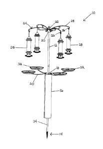
Figure 1 is perspective view of a first embodiment of the invention;
Figure 2 is a perspective view of a further embodiment of the present
invention;
Figure 3 is a perspective of a still further embodiment of the present
invention;
Figure 4 is a cross-sectional view illustrating the hub member of the present
invention;
Figure 5 is a perspective view of the bottom of a hub according to the present

invention;
Figure 6 is an exploded view of an embodiment of the present invention;
Figure 7 is a perspective view illustrating the bottom of the inner and outer
walls
forming a hub member; and
Figure 8 is a partial perspective view of the hub member.
DETAILED DESCRIPTION OF THE INVENTION
Referring to the drawings in greater detail and by reference characters
thereto, there
is illustrated in Figure 1 a first embodiment of the present invention wherein
there is shown
a pole system generally designated by reference numeral 10.
Pole system 10 includes a pole 12 which, in some embodiments, may be formed of
a
plurality of components suitably secured together. As seen, pole 12 includes a

screwthreaded end segment 14. Screwthreaded end system 14 is preferably formed
to have
- 3 -

CA 02948522 2016-11-14
a double helical screw on the outside thereof. The double helical screw
preferably includes
a first thread which extends outwardly from the base by a first distance, and
a second thread
which extends outwardly from the base by a second distance, with the first
distance being
greater than the second distance.
As may be seen in Figure 1, the lower portion of pole 12 is surrounded by a
baffle 16
in order to deny access to animals attempting to climb the pole system. Both
pole 12 and
baffle 16 may be formed of any suitable material and in the preferred
embodiment, are
formed of a metallic material.
In the embodiment illustrated in Figure 1, pole system 10 includes a lower hub
18 and
an upper hub 20 which will be described in greater detail hereinbelow.
The top of the pole is capped with a finial 22.
Upper hub 20 has a plurality of upper supporting members 24 mounted therein as
will
be discussed in greater detail hereinbelow. Each upper supporting member 24
has a curled
end forming a hook 26. Mounted on upper supporting members 24 are bird feeders

generally designated by reference numeral 28. Each bird feeder 28 may be any
suitable type
known in the art.
Lower hub 18 also supports lower supporting members 30 which extend outwardly
therefrom. Each lower supporting member 30 has a tray 32 associated therewith.
Trays 32
are mounted so as to be below a respective bird feeder 28. When feeding from
bird
feeders 28, certain birds discard a number of seeds. These stray seeds can
kill vegetation
located below the bird feeder. In the present case, each tray 32 will catch
the excess seed
and other birds may eat the same.
- 4 -

CA 02948522 2016-11-14
Pole 12 includes a plurality of apertures 34 formed therein. Pole apertures 34
are
designed to receive a member to allow the support of hubs 18, 20.
Turning to the embodiment of Figure 2, there is illustrated a modification of
the pole
system of Figure 1. In the arrangement of Figure 2, there is provided an
intermediate hub
and container generally designated by reference numeral 36. There is also
provided a lower
hub and a container generally designated by reference numeral 38.
Turning to Figure 3, there is illustrated a pole system wherein pole 12 is
comprised of
a plurality of pole sections 42. In lieu of a threaded end segment, there is
provided a
base 44 for support of pole sections 42.
Figures 4 to 8 illustrate a hub member 20. Hub member 20 is formed to have an
outer wall 48 and an inner wall 50. Inner wall 50 has a scalloped bottom wall
52.
Scalloped bottom wall 52 comprises a plurality of arcuate recesses 54. Each
arcuate recess
is defined by a first sloping wall 56 and a second sloping wall 58 which meet
at an arcuate
seat 60. Extending between outer wall 48 and inner wall 50 are a plurality of
transverse
walls 62 which define a plurality of inner channels. The inner channels are
designed to
receive supporting members 24. Each supporting member 24 includes a vertical
segment 64
designed to fit within one of the channels. Connecting with vertical segment
64 is an
outwardly extending support arm 66 which in turn has a downwardly extending
segment 68
which reinforces support arm 66 and also provides an abutting portion against
outer wall 48.
As may be seen in the drawings, a support pin 70 extends through an aperture
34 in pole 12
and is designed to fit within arcuate recess 54.
The arrangement is such that support pin 70 can ride up one of the sloping
walls 56 to
- 5 -

CA 02948522 2016-11-14
seat within an adjacent arcuate recess 54 if sufficient force is applied to
hub 20. Such may
be the case, for example, when exterior forces such as wind and/or a person
knocking one of
the arms supplies such a force.
As seen in Figures 5 and 6, a projection 78 is formed on outer wall 48 where
downwardly extending segment 68 abuts the outer wall 48. A slot 80 is formed
in the upper
marginal edge of outer wall 48 to receive support arm 66.
- 6 -

Dessin représentatif
Une figure unique qui représente un dessin illustrant l'invention.
États administratifs

Pour une meilleure compréhension de l'état de la demande ou brevet qui figure sur cette page, la rubrique Mise en garde , et les descriptions de Brevet , États administratifs , Taxes périodiques et Historique des paiements devraient être consultées.

États administratifs

Titre Date
Date de délivrance prévu 2019-07-30
(22) Dépôt 2016-11-14
(41) Mise à la disponibilité du public 2017-05-13
Requête d'examen 2019-03-25
(45) Délivré 2019-07-30

Historique d'abandonnement

Il n'y a pas d'historique d'abandonnement

Taxes périodiques

Dernier paiement au montant de 100,00 $ a été reçu le 2023-11-08


 Montants des taxes pour le maintien en état à venir

Description Date Montant
Prochain paiement si taxe générale 2024-11-14 277,00 $
Prochain paiement si taxe applicable aux petites entités 2024-11-14 100,00 $

Avis : Si le paiement en totalité n'a pas été reçu au plus tard à la date indiquée, une taxe supplémentaire peut être imposée, soit une des taxes suivantes :

  • taxe de rétablissement ;
  • taxe pour paiement en souffrance ; ou
  • taxe additionnelle pour le renversement d'une péremption réputée.

Les taxes sur les brevets sont ajustées au 1er janvier de chaque année. Les montants ci-dessus sont les montants actuels s'ils sont reçus au plus tard le 31 décembre de l'année en cours.
Veuillez vous référer à la page web des taxes sur les brevets de l'OPIC pour voir tous les montants actuels des taxes.

Historique des paiements

Type de taxes Anniversaire Échéance Montant payé Date payée
Le dépôt d'une demande de brevet 200,00 $ 2016-11-14
Taxe de maintien en état - Demande - nouvelle loi 2 2018-11-14 50,00 $ 2018-10-16
Requête d'examen 400,00 $ 2019-03-25
Taxe finale 150,00 $ 2019-06-12
Taxe de maintien en état - brevet - nouvelle loi 3 2019-11-14 50,00 $ 2019-11-05
Taxe de maintien en état - brevet - nouvelle loi 4 2020-11-16 50,00 $ 2020-11-12
Enregistrement de documents 100,00 $ 2021-03-25
Taxe de maintien en état - brevet - nouvelle loi 5 2021-11-15 100,00 $ 2021-11-12
Taxe de maintien en état - brevet - nouvelle loi 6 2022-11-14 100,00 $ 2022-11-14
Taxe de maintien en état - brevet - nouvelle loi 7 2023-11-14 100,00 $ 2023-11-08
Titulaires au dossier

Les titulaires actuels et antérieures au dossier sont affichés en ordre alphabétique.

Titulaires actuels au dossier
BROME BIRD CARE INC.
Titulaires antérieures au dossier
COTE, PAUL L.
Les propriétaires antérieurs qui ne figurent pas dans la liste des « Propriétaires au dossier » apparaîtront dans d'autres documents au dossier.
Documents

Pour visionner les fichiers sélectionnés, entrer le code reCAPTCHA :


Pour visualiser une image, cliquer sur un lien dans la colonne description du document. Pour télécharger l'image (les images), cliquer l'une ou plusieurs cases à cocher dans la première colonne et ensuite cliquer sur le bouton "Télécharger sélection en format PDF (archive Zip)" ou le bouton "Télécharger sélection (en un fichier PDF fusionné)".

Liste des documents de brevet publiés et non publiés sur la BDBC .

Si vous avez des difficultés à accéder au contenu, veuillez communiquer avec le Centre de services à la clientèle au 1-866-997-1936, ou envoyer un courriel au Centre de service à la clientèle de l'OPIC.


Description du
Document 
Date
(yyyy-mm-dd) 
Nombre de pages   Taille de l'image (Ko) 
Changement à la méthode de correspondance 2021-03-25 5 152
Lettre du bureau 2021-05-26 2 199
Paiement de taxe périodique 2022-11-14 1 33
Abrégé 2016-11-14 1 15
Description 2016-11-14 6 211
Revendications 2016-11-14 1 30
Dessins 2016-11-14 8 134
ATDB OEA 2019-03-25 3 178
Requête ATDB (PPH) 2019-03-25 6 200
Revendications 2019-03-25 2 42
Taxe finale 2019-06-12 1 31
Page couverture 2019-07-03 1 31
Nouvelle demande 2016-11-14 2 67
Dessins représentatifs 2017-04-11 1 5
Page couverture 2017-04-11 2 35