Language selection

Search

Patent 3084485 Summary

Third-party information liability

Some of the information on this Web page has been provided by external sources. The Government of Canada is not responsible for the accuracy, reliability or currency of the information supplied by external sources. Users wishing to rely upon this information should consult directly with the source of the information. Content provided by external sources is not subject to official languages, privacy and accessibility requirements.

Claims and Abstract availability

Any discrepancies in the text and image of the Claims and Abstract are due to differing posting times. Text of the Claims and Abstract are posted:

  • At the time the application is open to public inspection;
  • At the time of issue of the patent (grant).
(12) Patent: (11) CA 3084485
(54) English Title: WHEEL RETENTION SYSTEM
(54) French Title: SYSTEME DE RETENUE DE ROUE
Status: Granted
Bibliographic Data
(51) International Patent Classification (IPC):
  • B60B 27/00 (2006.01)
(72) Inventors :
  • DUNNA, PAVAN KUMAR (United States of America)
  • DESHMUKH, KAUSTUBH (United States of America)
(73) Owners :
  • CONSOLIDATED METCO, INC. (United States of America)
(71) Applicants :
  • CONSOLIDATED METCO, INC. (United States of America)
(74) Agent: GOWLING WLG (CANADA) LLP
(74) Associate agent:
(45) Issued: 2022-04-26
(86) PCT Filing Date: 2018-10-25
(87) Open to Public Inspection: 2019-05-02
Examination requested: 2020-04-22
Availability of licence: N/A
(25) Language of filing: English

Patent Cooperation Treaty (PCT): Yes
(86) PCT Filing Number: PCT/US2018/057537
(87) International Publication Number: WO2019/084281
(85) National Entry: 2020-04-22

(30) Application Priority Data:
Application No. Country/Territory Date
15/794,595 United States of America 2017-10-26

Abstracts

English Abstract

A wheel retention system is provided for retaining a wheel on a vehicle. The system includes a plurality of connector receiving openings in a wheel hub flange, with each wheel hub flange including a raised bolt stop at each bolt receiving opening. A plurality of threaded connectors or bolts is provided, with each bolt received in one of the bolt receiving openings. Each bolt has a head with a flattened or clipped surface that meshes with the raised bolt stop in each bolt receiving opening on the wheel hub flange. These raised bolt stops positively prevent the bolts from rotating in the openings.


French Abstract

L'invention concerne un système de retenue de roue conçu pour retenir une roue sur un véhicule. Le système comprend une pluralité d'ouvertures de réception de connecteur dans une bride de moyeu de roue, chaque bride de moyeu de roue comprenant une butée de boulon surélevée au niveau de chaque ouverture de réception de boulon. Une pluralité de connecteurs filetés ou de boulons sont prévus, chaque boulon étant reçu dans l'une des ouvertures de réception de boulon. Chaque boulon a une tête avec une surface aplatie ou clipsée qui s'engrène avec la butée de boulon surélevée dans chaque ouverture de réception de boulon sur la bride de moyeu de roue. Les butées de boulon surélevées de l'invention empêchent par liaison de force les boulons de tourner dans les ouvertures.

Claims

Note: Claims are shown in the official language in which they were submitted.

WHAT IS CLAIMED IS:
1. A wheel retention assembly comprising:
a wheel hub having a flange with a plurality of openings and a bolt stop
raised section
adjacent each opening;
a plurality of threaded fasteners each having a length and configured to be
received in
one of the wheel flange openings,
each threaded fastener having an upper head and a lower shank, each upper head
having
an upper surface extending transverse to the length of the threaded fastener,
a side surface
extending along the length toward the lower shank, and an underside surface
extending inwardly
from the side surface to the lower shank,
each upper head side surface having a flattened portion,
the flattened portion of the upper head side surface of each threaded fastener
head
configured to be in confronting relation with one of the bolt stop raised
sections of the wheel hub
flange and inhibit rotation of the threaded fastener with the lower shank of
the threaded fastener
extending in the opening adjacent the one bolt stop raised section and the
underside surface of
the threaded fastener head seated against the wheel hub flange,
the wheel hub bolt stop raised sections each include an upstanding wall
extending
tangentially to the adjacent opening.
2. The wheel retention assembly of claim 1 wherein:
each threaded fastener comprising a threaded portion extending axially through
the wheel
hub flange opening and beyond the wheel flange.
3. The wheel retention assembly of claim 1 wherein:
6

the wheel hub bolt stop raised sections include planar surfaces configured to
abut the
flattened portions of the upper head side surfaces of the threaded fasteners.
4. The wheel retention assembly of claim 1 wherein:
the threaded fasteners are received in the wheel hub flange openings in
clearance fit.
5. The wheel retention assembly of claim I wherein the bolt stop raised
sections and the
flange of the wheel hub have a unitary, one-piece construction.
6. A wheel retention assembly comprising:
a wheel hub having a flange with a plurality of openings and a bolt stopraised
section
adjacent each opening,
a plurality of threaded fasteners each having a length and configured to be
received in
=one of the wheel flange openings,
each threaded fastener having an upper head and a lower shank, each upper head
having
= an upper surface extending transverse to the length of the threaded
fastener, a side surface
extending along the length toward the lower shank, and an underside surface
extending inwardly
from the side surface to the lower shank,
each upper head side surface having a flattened portion,
the flattened portion of the upper head side surface of each threaded fastener
head
configured to be in confronting relation with one of the bolt stop raised
sections of the wheel hub
flange and inhibit rotation of the threaded fastener with the lower shank of
the threaded fastener
extending in the opening adjacent the one bolt stop raised section and the
underside surface of
the threaded fastener head seated against the wheel hub flange,
the wheel hub flange openings each have a circumference,
7

the wheel hub bolt stop raised section extends for less than the entire
circumference of
the adjacent wheel hub flange opening.
7. A wheel retention assembly comprising:
a wheel hub having a flange with a plurality of openings and a bolt stop
raised section
adjacent each opening,
a plurality of threaded fasteners each having a length and configured to be
received in
one of the wheel flange openings,
each threaded fastener having an upper head and a lower shank, each upper head
having
an upper surface extending transverse to the length of the threaded fastener,
a side surface
extending along the length toward the lower shank, and an underside surface
extending inwardly
from the side surface to the lower shank,
each upper head side surface having a flattened portion,
the flattened portion of the upper head side surface of each threaded fastener
head
configured to be in confronting relation with one of the bolt stop raised
sections of the wheel hub
flange and inhibit rotation of the threaded fastener with the lower shank of
the threaded fastener
extending in the opening adjacent the one bolt stop raised section and the
underside surface of
the threaded fastener head seated against the wheel hub flange,
wherein the bolt stop raised sections each include:
an upper stop surface configured to abut the flattened portion of the upper
head side
surface of one of the threaded fasteners; and
a lower undercut below the upper stop surface.
8. The wheel retention assembly of claim I wherein:
8

the wheel hub bolt stop raised section is integral with the hub flange and
extends axially
from an outer edge of the wheel hub flange.
9. A wheel retention assembly comprising:
a wheel hub having a flange with a plurality of openings and a bolt stop
raised section
adjacent each opening, each opening having a circumference thereof;
the bolt stop raised section of the wheel hub flange extending for less than
the entire
circumference of the adjacent opening;
a plurality of threaded connectors each configured to be received in one of
the wheel
flange openings,
each threaded connector having a head with a flattened portion configured to
contact the
bolt stop raised section of each wheel hub flange and limit turning of the
threaded connector.
10. The wheel retention assembly of claim 9 wherein:
each threaded connector comprises a threaded portion extending axially through
the
wheel hub flange opening and beyond the wheel flange.
11. The wheel retention assembly of claim 9 wherein the openings of the flange
are each
circular, and
wherein each bolt stop raised section has a planar stop surface extending
normal to a
radius of the adjacent opening.
12. The wheel retention assembly of claim 9 wherein:
the threaded connector is received in the wheel hub flange opening in a
clearance fit.
13. The wheel retention assembly of claim 9 wherein the bolt stop raised
sections and the
flange of the wheel hub have a unitary, one-piece construction.
14. The wheel retention assembly of claim 9 wherein:
9

the wheel hub bolt stop raised section is integral with the hub flange and
extends axially
frorn an outer edge of the wheel hub flange.
15. The wheel retention assembly of claim 9 wherein the bolt stop raised
sections each
include:
an upper surface configured to abut the head flattened portion of one of the
threaded
connectors; and
a lower undercut below the upper surface.
16. The wheel retention assembly of claim 9 wherein:
the wheel hub bolt stop raised sections each include an upstanding wall
extending
tangentially to one of the threaded connector heads.
17. A wheel retention assembly comprising:
a wheel hub having a flange with a plurality of openings and a stop adjacent
each
opening;
a plurality of elongate connectors each having an upper head, a lower shank,
and a length
extending therebetween;
the lower shank of each connector configured to extend in one of the openings
of the
flange;
the upper head of each connector having an upper surface extending transverse
to the
length of the connector, a side surface extending along the length toward the
lower shank, and an
underside surface extending inwardly from the side surface to the lower shank;
a flattened portion of the upper head side surface of each connector head
configured to be
in confronting relation with one of the stops of the wheel hub flange with the
lower shank of the

connector extending in the opening adjacent the one stop and the underside
surface of the
connector upper head seated against the wheel hub flange,
wherein each stop includes an upper stop surface configured to abut the
flattened portion
of the upper head side surface of the connector, and
a lower undercut below the upper stop surface.
18. A wheel retention assembly comprising:
a wheel hub having a flange with a plurality of openings and a stop adjacent
each
opening;
a plurality of elongate connectors each having an upper head, a lower shank,
and a length
extending therebetween;
the lower shank of each connector configured to extend in one of the openings
of the
flange;
the upper head of each connector having an upper surface extending transverse
to the
length of the connector, a side surface extending along the length toward the
lower shank, and an
underside surface extending inwardly from the side surface to the lower shank;
a flattened portion of the upper head side surface of each connector head
configured to be
in confronting relation with one of the stops of the wheel hub flange with the
lower shank of the
connector extending in the opening adjacent the one stop and the underside
surface of the
connector upper head seated against the wheel hub flange;
wherein each opening of the wheel hub flange has a circumference; and
wherein each stop extends for less than the entire circumference of the
adjacent opening.
1 1

19. The wheel retention assembly of claim 17 wherein each upper stop surface
includes a
planar surface configured to abut the flattened portion of the upper head side
surface of the
connector.
20. The wheel retention assembly of claim 17 wherein the stops and the flange
of the
wheel hub have a unitary, one-piece construction.
21. A wheel retention assembly comprising:
a wheel hub having a flange with a plurality of openings and a stop adjacent
each
opening;
a plurality of elongate connectors each having an upper head, a lower shank,
and a length
extending therebetween;
the lower shank of each connector configured to extend in one of the openings
of the
flange;
the upper head of each connector having an upper surface extending transverse
to the
length of the connector, a side surface extending along the length toward the
lower shank, and an
underside surface extending inwardly from the side surface to the lower shank;
a flattened portion of the upper head side surface of each connector head
configured to be
in confronting relation with one of the stops of the wheel hub flange with the
lower shank of the
connector extending in the opening adjacent the one stop and the underside
surface of the
connector upper head seated against the wheel hub flange,
wherein each stop includes an upstanding wall extending tangentially to the
adjacent
opening.
22. The wheel retention assembly of claim 17 wherein:
the connectors are received in the wheel hub flange openings in clearance fit.
12

Description

Note: Descriptions are shown in the official language in which they were submitted.


CA 03084485 2020-04-22
WO 2019/084281
PCT/US2018/057537
WHEEL RETENTION SYSTEM
BACKGROUND OF THE INVENTION
The present invention relates generally to a wheel hub system which retains
wheels on
commercial vehicles, and more particularly to a system employing a threaded
connector which
mates with a wheel hub opening having a bolt stop.
Conventionally, wheel hubs are made out of ductile iron or aluminum, which are

machined and assembled to mate with other components of a vehicle. For
example, FIGs. 2 and
2A provide a view of a generally bell-shaped prior art wheel hub H attached in
a conventional
manner to a vehicle axle (not shown). A connector, such as a stud or bolt B
extends through a
.. bored cylindrical hole C defined by a mounting flange D of hub H. Typically
a plurality of holes
C are equally spaced around the periphery of the wheel hub mounting flange D,
each receiving a
bolt B.
The bolts B are used to secure together the hub H, sometimes a brake drum (not
shown),
and a wheel (not shown) upon which is mounted a tire (not shown). The bolts B
each have a head
J at one end, and a threaded portion K at the opposite end. A wheel nut (not
shown) engages the
bolt threaded portion K to secure the wheel to the hub H. The bolt B has a
serrated shoulder
portion M which is typically press-fit into cylindrical hole C to affix the
bolt to hub H. The bolt
head J has undersurface N, which is substantially perpendicular to a
longitudinal axis of bolt B,
and is seated substantially flat against the hub inboard surface E.
A vehicle wheel hub H is typically subjected to two types of stress which
limit service
life: (1) the mean stress imparted by tightening the wheel nuts, which has the
effect of drawing
the hub inboard surface E down into hole C; (2) stress caused by the serrated
surface of the
threaded bolt resisting rotation in the opening in the wheel flange due to the
interference fit of
1

CA 03084485 2020-04-22
WO 2019/084281
PCT/US2018/057537
the serrated portion of the bolt in the wheel flange opening. The combined
stresses have a
25 negative impact on the service life of the wheel hub H. Additionally, it
is quite common for
mechanics to over-tighten the wheel nuts when changing tires, resulting in
over-stretching or
over-tensioning the bolts B and further increasing the stress, which shortens
the service life of
the wheel hub H.
SUMMARY OF THE INVENTION
30 One embodiment of the present invention is directed to a wheel
retention system for
retaining a wheel on a vehicle. The system includes a plurality of bolt
receiving openings in the
wheel hub flange, with each wheel hub flange including a raised bolt stop at
each bolt receiving
opening. A plurality of threaded connectors or bolts is provided, with each
bolt received in one
of the bolt receiving openings. Each bolt has a head with a flattened or
clipped surface that
35 meshes with the raised bolt stop in each bolt receiving opening on the
wheel hub flange. These
raised bolt stops positively prevent the bolts from rotating in the openings.
The advantage of the
assembly is that it restricts rotation of the stud and reduces the stress in
the hub mounting flange
area.
DESCRIPTION OF THE DRAWINGS
40 In the drawings,
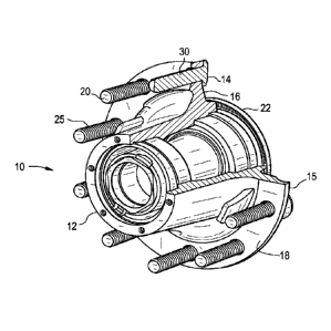
FIG. 1 is a perspective, partial cut away view of a prior art wheel hub.
FIG. 2 is a perspective view of a prior art wheel hub and components;
FIG. 2A is a side view of a prior art threaded fastener;
FIG. 3 is a perspective view of a wheel hub and components according to one
embodiment of the
45 present invention;
FIG. 4 is a perspective, partial cut away view of a wheel hub and components
according to one
2

CA 03084485 2020-04-22
WO 2019/084281
PCT/US2018/057537
embodiment of the present invention;
FIG. 5 is a perspective view of a wheel hub and components according to one
embodiment of the
present invention;
50 FIG. 6 is a perspective, exploded view of a wheel hub and components
according to one
embodiment of the present invention;
FIG. 7 is a perspective view of a wheel hub according to one embodiment of the
present
invention;
FIG. 8 is a side cut away view of a wheel hub according to one embodiment of
the present
55 invention;
FIG. 9 is a partial, side cut away view of a wheel hub according to one
embodiment of the
present invention;
FIG. 10 is a top view of a threaded fastener in accordance with one embodiment
of the present
invention;
60 FIG. 11 is a side view of a threaded fastener in accordance with one
embodiment of the present
invention;
FIG. 12 is a side cut away view of a threaded fastener in an opening in a
wheel hub flange in
accordance with one embodiment of the present invention, and
FIG. 13 is a top view of a threaded fastener in an opening in a wheel hub
flange in accordance
65 with one embodiment of the present invention.
DETAILED DESCRIPTION
FIG. 1 illustrates a prior art wheel retention system 10 according to one
embodiment of
the invention. System 10 includes a roughly bell-shaped wheel hub 12 having a
barrel portion
which attaches to an axleby bearings. A cylindrical opening 14, which may be
formed by a
3

CA 03084485 2020-04-22
WO 2019/084281
PCT/US2018/057537
70 drilling operation, is defined by an outer peripheral mounting flange 15
of the wheel hub 12.
Opening 14 extends from an inboard surface 16 to an outboard surface 18 of
wheel hub
mounting flange 15.
A connector, such as a threaded wheel bolt 20, is illustrated with the shank
22 at one end,
and a threaded portion 25 at an opposing end. Shank 22 is fitted into a
cylindrical opening 14 of
75 the wheel hub mounting flange 15. The bolt shank 22 extends through
opening 14. A wheel nut
(not shown) engages the bolt portion 25 having threads to mount a wheel and
tire on wheel hub
12. The bolt 20 has a head 30 with an undersurface 32 serving as a contact
surface with the
inboard surface 16 of wheel hub flange 15. Typically a plurality of openings
14 are equally
spaced around the periphery of the wheel hub mounting flange 15, each
receiving a bolt 20, with
80 the number of bolts depending upon the mounting system bolt circle
diameter.
A detailed view of a prior art wheel hub and threaded fastener are shown in
FIGs. 2 and 2A and
are described above.
FIGS. 3 and 4 illustrate an embodiment of wheel retention system 10 according
to the
present invention. As particularly shown, wheel hub mounting flange 15
includes an integral
85 bolt stop 31 adjacent each opening 14. Bolt stop 31 is seen to comprise
a radially inner facing
flat surface 36 that covers about 90 degrees of cylindrical opening 14. Bolt
stop 31 also is
comprised of an axially outer edge 32. Bolt stop 31 is seen to be integral
with and extend from
an outer radial edge of wheel hub flange 15.
In FIGs. 5 and 6, wheel hub 12 is seen with wheel hub mounting flange 15. Bolt
stop 31
90 is seen with inner facing flat surface 36 against which corresponding
flat surface 21 of bolt head
30 meshes or abuts.
4

CA 03084485 2020-04-22
WO 2019/084281
PCT/US2018/057537
Bolt 20 with shank 22 is seen to pass through cylindrical opening 14 with any
type of fit,
meaning there can be a clearance to an interference fit between the shank and
the opening. While
shank 22 may include serrations, it is meant to pass through opening 14 in a
little to no
95 interference manner. In sum, while bolt 20 with shank 22 is held in
opening 14, it is not
necessarily press fit to pass there through. Accordingly, there is little to
no stress on wheel hub
mounting flange 15 due to bolt 20 passing through opening 14.
However, bolt head 30 includes a flat section 21 that corresponds to about 90
degrees of
the circumference of bolt head 30. Bolt head flat section 21 meshes or abuts
flat surface 36 of
100 bolt stop 31. This meshing provides the rotational restriction for bolt
20 to allow wheel nuts to
be assembled thereon and accordingly hold the brake drum (if present) and
wheel to wheel hub
12.
Referring now to FIGs. 7, 8 and 9, detailed views of wheel hub 12 with bolt
stop 31 are
provided. As particularly shown, wheel hub mounting flange 15 includes an
integral bolt stop 31
105 adjacent each opening 14. Bolt stop 31 is seen to comprise a radially
inner facing flat surface 36
that covers about 90 degrees of cylindrical opening 14. Bolt stop 31 also is
comprised of an
axially outer edge 32. Bolt stop 31 is seen to be integral with and extend
from an outer radial
edge of wheel hub flange 15.
Referring now to FIGs. 10, 11, 12, and 13, threaded wheel bolt 20, is
illustrated with the
110 shank 22 at one end, and a threaded portion 25 at an opposing end. Bolt
head 30 includes a flat
section 21 that corresponds to about 90 degrees of the circumference of bolt
head 30. Bolt head
flat section 21 meshes or abuts flat surface 36 of bolt stop 31. This meshing
provides the
rotational restriction for bolt 20 to allow wheel nuts to be assembled on the
threaded section 25
and accordingly hold the brake drum (if present) and wheel to wheel hub 12.

Representative Drawing
A single figure which represents the drawing illustrating the invention.
Administrative Status

For a clearer understanding of the status of the application/patent presented on this page, the site Disclaimer , as well as the definitions for Patent , Administrative Status , Maintenance Fee  and Payment History  should be consulted.

Administrative Status

Title Date
Forecasted Issue Date 2022-04-26
(86) PCT Filing Date 2018-10-25
(87) PCT Publication Date 2019-05-02
(85) National Entry 2020-04-22
Examination Requested 2020-04-22
(45) Issued 2022-04-26

Abandonment History

There is no abandonment history.

Maintenance Fee

Last Payment of $210.51 was received on 2023-09-20


 Upcoming maintenance fee amounts

Description Date Amount
Next Payment if standard fee 2024-10-25 $277.00
Next Payment if small entity fee 2024-10-25 $100.00

Note : If the full payment has not been received on or before the date indicated, a further fee may be required which may be one of the following

  • the reinstatement fee;
  • the late payment fee; or
  • additional fee to reverse deemed expiry.

Patent fees are adjusted on the 1st of January every year. The amounts above are the current amounts if received by December 31 of the current year.
Please refer to the CIPO Patent Fees web page to see all current fee amounts.

Payment History

Fee Type Anniversary Year Due Date Amount Paid Paid Date
Registration of a document - section 124 2020-04-22 $100.00 2020-04-22
Application Fee 2020-04-22 $400.00 2020-04-22
Request for Examination 2023-10-25 $800.00 2020-04-22
Maintenance Fee - Application - New Act 2 2020-10-26 $100.00 2020-09-18
Maintenance Fee - Application - New Act 3 2021-10-25 $100.00 2021-09-21
Final Fee 2022-03-30 $305.39 2022-02-02
Maintenance Fee - Patent - New Act 4 2022-10-25 $100.00 2022-09-22
Maintenance Fee - Patent - New Act 5 2023-10-25 $210.51 2023-09-20
Owners on Record

Note: Records showing the ownership history in alphabetical order.

Current Owners on Record
CONSOLIDATED METCO, INC.
Past Owners on Record
None
Past Owners that do not appear in the "Owners on Record" listing will appear in other documentation within the application.
Documents

To view selected files, please enter reCAPTCHA code :


To view images, click a link in the Document Description column. To download the documents, select one or more checkboxes in the first column and then click the "Download Selected in PDF format (Zip Archive)" or the "Download Selected as Single PDF" button.

List of published and non-published patent-specific documents on the CPD .

If you have any difficulty accessing content, you can call the Client Service Centre at 1-866-997-1936 or send them an e-mail at CIPO Client Service Centre.


Document
Description 
Date
(yyyy-mm-dd) 
Number of pages   Size of Image (KB) 
Abstract 2020-04-22 2 75
Claims 2020-04-22 4 107
Drawings 2020-04-22 7 173
Description 2020-04-22 5 193
Representative Drawing 2020-04-22 1 26
Patent Cooperation Treaty (PCT) 2020-04-22 1 97
International Preliminary Report Received 2020-04-22 7 316
International Search Report 2020-04-22 1 50
National Entry Request 2020-04-22 11 506
Cover Page 2020-08-06 1 61
Electronic Grant Certificate 2022-04-26 1 2,527
Examiner Requisition 2021-05-21 6 256
Amendment 2021-06-09 13 397
Claims 2021-06-09 7 257
Drawings 2021-06-09 7 175
Interview Record Registered (Action) 2021-08-19 1 30
Amendment 2021-08-19 5 224
Claims 2021-08-19 7 268
Final Fee 2022-02-02 4 88
Representative Drawing 2022-03-31 1 17
Cover Page 2022-03-31 1 49