Sélection de la langue

Search

Sommaire du brevet 3084485 

Énoncé de désistement de responsabilité concernant l'information provenant de tiers

Une partie des informations de ce site Web a été fournie par des sources externes. Le gouvernement du Canada n'assume aucune responsabilité concernant la précision, l'actualité ou la fiabilité des informations fournies par les sources externes. Les utilisateurs qui désirent employer cette information devraient consulter directement la source des informations. Le contenu fourni par les sources externes n'est pas assujetti aux exigences sur les langues officielles, la protection des renseignements personnels et l'accessibilité.

Disponibilité de l'Abrégé et des Revendications

L'apparition de différences dans le texte et l'image des Revendications et de l'Abrégé dépend du moment auquel le document est publié. Les textes des Revendications et de l'Abrégé sont affichés :

  • lorsque la demande peut être examinée par le public;
  • lorsque le brevet est émis (délivrance).
(12) Brevet: (11) CA 3084485
(54) Titre français: SYSTEME DE RETENUE DE ROUE
(54) Titre anglais: WHEEL RETENTION SYSTEM
Statut: Octroyé
Données bibliographiques
(51) Classification internationale des brevets (CIB):
  • B60B 27/00 (2006.01)
(72) Inventeurs :
  • DUNNA, PAVAN KUMAR (Etats-Unis d'Amérique)
  • DESHMUKH, KAUSTUBH (Etats-Unis d'Amérique)
(73) Titulaires :
  • CONSOLIDATED METCO, INC. (Etats-Unis d'Amérique)
(71) Demandeurs :
  • CONSOLIDATED METCO, INC. (Etats-Unis d'Amérique)
(74) Agent: GOWLING WLG (CANADA) LLP
(74) Co-agent:
(45) Délivré: 2022-04-26
(86) Date de dépôt PCT: 2018-10-25
(87) Mise à la disponibilité du public: 2019-05-02
Requête d'examen: 2020-04-22
Licence disponible: S.O.
(25) Langue des documents déposés: Anglais

Traité de coopération en matière de brevets (PCT): Oui
(86) Numéro de la demande PCT: PCT/US2018/057537
(87) Numéro de publication internationale PCT: WO2019/084281
(85) Entrée nationale: 2020-04-22

(30) Données de priorité de la demande:
Numéro de la demande Pays / territoire Date
15/794,595 Etats-Unis d'Amérique 2017-10-26

Abrégés

Abrégé français

L'invention concerne un système de retenue de roue conçu pour retenir une roue sur un véhicule. Le système comprend une pluralité d'ouvertures de réception de connecteur dans une bride de moyeu de roue, chaque bride de moyeu de roue comprenant une butée de boulon surélevée au niveau de chaque ouverture de réception de boulon. Une pluralité de connecteurs filetés ou de boulons sont prévus, chaque boulon étant reçu dans l'une des ouvertures de réception de boulon. Chaque boulon a une tête avec une surface aplatie ou clipsée qui s'engrène avec la butée de boulon surélevée dans chaque ouverture de réception de boulon sur la bride de moyeu de roue. Les butées de boulon surélevées de l'invention empêchent par liaison de force les boulons de tourner dans les ouvertures.


Abrégé anglais

A wheel retention system is provided for retaining a wheel on a vehicle. The system includes a plurality of connector receiving openings in a wheel hub flange, with each wheel hub flange including a raised bolt stop at each bolt receiving opening. A plurality of threaded connectors or bolts is provided, with each bolt received in one of the bolt receiving openings. Each bolt has a head with a flattened or clipped surface that meshes with the raised bolt stop in each bolt receiving opening on the wheel hub flange. These raised bolt stops positively prevent the bolts from rotating in the openings.

Revendications

Note : Les revendications sont présentées dans la langue officielle dans laquelle elles ont été soumises.


WHAT IS CLAIMED IS:
1. A wheel retention assembly comprising:
a wheel hub having a flange with a plurality of openings and a bolt stop
raised section
adjacent each opening;
a plurality of threaded fasteners each having a length and configured to be
received in
one of the wheel flange openings,
each threaded fastener having an upper head and a lower shank, each upper head
having
an upper surface extending transverse to the length of the threaded fastener,
a side surface
extending along the length toward the lower shank, and an underside surface
extending inwardly
from the side surface to the lower shank,
each upper head side surface having a flattened portion,
the flattened portion of the upper head side surface of each threaded fastener
head
configured to be in confronting relation with one of the bolt stop raised
sections of the wheel hub
flange and inhibit rotation of the threaded fastener with the lower shank of
the threaded fastener
extending in the opening adjacent the one bolt stop raised section and the
underside surface of
the threaded fastener head seated against the wheel hub flange,
the wheel hub bolt stop raised sections each include an upstanding wall
extending
tangentially to the adjacent opening.
2. The wheel retention assembly of claim 1 wherein:
each threaded fastener comprising a threaded portion extending axially through
the wheel
hub flange opening and beyond the wheel flange.
3. The wheel retention assembly of claim 1 wherein:
6

the wheel hub bolt stop raised sections include planar surfaces configured to
abut the
flattened portions of the upper head side surfaces of the threaded fasteners.
4. The wheel retention assembly of claim 1 wherein:
the threaded fasteners are received in the wheel hub flange openings in
clearance fit.
5. The wheel retention assembly of claim I wherein the bolt stop raised
sections and the
flange of the wheel hub have a unitary, one-piece construction.
6. A wheel retention assembly comprising:
a wheel hub having a flange with a plurality of openings and a bolt stopraised
section
adjacent each opening,
a plurality of threaded fasteners each having a length and configured to be
received in
=one of the wheel flange openings,
each threaded fastener having an upper head and a lower shank, each upper head
having
= an upper surface extending transverse to the length of the threaded
fastener, a side surface
extending along the length toward the lower shank, and an underside surface
extending inwardly
from the side surface to the lower shank,
each upper head side surface having a flattened portion,
the flattened portion of the upper head side surface of each threaded fastener
head
configured to be in confronting relation with one of the bolt stop raised
sections of the wheel hub
flange and inhibit rotation of the threaded fastener with the lower shank of
the threaded fastener
extending in the opening adjacent the one bolt stop raised section and the
underside surface of
the threaded fastener head seated against the wheel hub flange,
the wheel hub flange openings each have a circumference,
7

the wheel hub bolt stop raised section extends for less than the entire
circumference of
the adjacent wheel hub flange opening.
7. A wheel retention assembly comprising:
a wheel hub having a flange with a plurality of openings and a bolt stop
raised section
adjacent each opening,
a plurality of threaded fasteners each having a length and configured to be
received in
one of the wheel flange openings,
each threaded fastener having an upper head and a lower shank, each upper head
having
an upper surface extending transverse to the length of the threaded fastener,
a side surface
extending along the length toward the lower shank, and an underside surface
extending inwardly
from the side surface to the lower shank,
each upper head side surface having a flattened portion,
the flattened portion of the upper head side surface of each threaded fastener
head
configured to be in confronting relation with one of the bolt stop raised
sections of the wheel hub
flange and inhibit rotation of the threaded fastener with the lower shank of
the threaded fastener
extending in the opening adjacent the one bolt stop raised section and the
underside surface of
the threaded fastener head seated against the wheel hub flange,
wherein the bolt stop raised sections each include:
an upper stop surface configured to abut the flattened portion of the upper
head side
surface of one of the threaded fasteners; and
a lower undercut below the upper stop surface.
8. The wheel retention assembly of claim I wherein:
8

the wheel hub bolt stop raised section is integral with the hub flange and
extends axially
from an outer edge of the wheel hub flange.
9. A wheel retention assembly comprising:
a wheel hub having a flange with a plurality of openings and a bolt stop
raised section
adjacent each opening, each opening having a circumference thereof;
the bolt stop raised section of the wheel hub flange extending for less than
the entire
circumference of the adjacent opening;
a plurality of threaded connectors each configured to be received in one of
the wheel
flange openings,
each threaded connector having a head with a flattened portion configured to
contact the
bolt stop raised section of each wheel hub flange and limit turning of the
threaded connector.
10. The wheel retention assembly of claim 9 wherein:
each threaded connector comprises a threaded portion extending axially through
the
wheel hub flange opening and beyond the wheel flange.
11. The wheel retention assembly of claim 9 wherein the openings of the flange
are each
circular, and
wherein each bolt stop raised section has a planar stop surface extending
normal to a
radius of the adjacent opening.
12. The wheel retention assembly of claim 9 wherein:
the threaded connector is received in the wheel hub flange opening in a
clearance fit.
13. The wheel retention assembly of claim 9 wherein the bolt stop raised
sections and the
flange of the wheel hub have a unitary, one-piece construction.
14. The wheel retention assembly of claim 9 wherein:
9

the wheel hub bolt stop raised section is integral with the hub flange and
extends axially
frorn an outer edge of the wheel hub flange.
15. The wheel retention assembly of claim 9 wherein the bolt stop raised
sections each
include:
an upper surface configured to abut the head flattened portion of one of the
threaded
connectors; and
a lower undercut below the upper surface.
16. The wheel retention assembly of claim 9 wherein:
the wheel hub bolt stop raised sections each include an upstanding wall
extending
tangentially to one of the threaded connector heads.
17. A wheel retention assembly comprising:
a wheel hub having a flange with a plurality of openings and a stop adjacent
each
opening;
a plurality of elongate connectors each having an upper head, a lower shank,
and a length
extending therebetween;
the lower shank of each connector configured to extend in one of the openings
of the
flange;
the upper head of each connector having an upper surface extending transverse
to the
length of the connector, a side surface extending along the length toward the
lower shank, and an
underside surface extending inwardly from the side surface to the lower shank;
a flattened portion of the upper head side surface of each connector head
configured to be
in confronting relation with one of the stops of the wheel hub flange with the
lower shank of the

connector extending in the opening adjacent the one stop and the underside
surface of the
connector upper head seated against the wheel hub flange,
wherein each stop includes an upper stop surface configured to abut the
flattened portion
of the upper head side surface of the connector, and
a lower undercut below the upper stop surface.
18. A wheel retention assembly comprising:
a wheel hub having a flange with a plurality of openings and a stop adjacent
each
opening;
a plurality of elongate connectors each having an upper head, a lower shank,
and a length
extending therebetween;
the lower shank of each connector configured to extend in one of the openings
of the
flange;
the upper head of each connector having an upper surface extending transverse
to the
length of the connector, a side surface extending along the length toward the
lower shank, and an
underside surface extending inwardly from the side surface to the lower shank;
a flattened portion of the upper head side surface of each connector head
configured to be
in confronting relation with one of the stops of the wheel hub flange with the
lower shank of the
connector extending in the opening adjacent the one stop and the underside
surface of the
connector upper head seated against the wheel hub flange;
wherein each opening of the wheel hub flange has a circumference; and
wherein each stop extends for less than the entire circumference of the
adjacent opening.
1 1

19. The wheel retention assembly of claim 17 wherein each upper stop surface
includes a
planar surface configured to abut the flattened portion of the upper head side
surface of the
connector.
20. The wheel retention assembly of claim 17 wherein the stops and the flange
of the
wheel hub have a unitary, one-piece construction.
21. A wheel retention assembly comprising:
a wheel hub having a flange with a plurality of openings and a stop adjacent
each
opening;
a plurality of elongate connectors each having an upper head, a lower shank,
and a length
extending therebetween;
the lower shank of each connector configured to extend in one of the openings
of the
flange;
the upper head of each connector having an upper surface extending transverse
to the
length of the connector, a side surface extending along the length toward the
lower shank, and an
underside surface extending inwardly from the side surface to the lower shank;
a flattened portion of the upper head side surface of each connector head
configured to be
in confronting relation with one of the stops of the wheel hub flange with the
lower shank of the
connector extending in the opening adjacent the one stop and the underside
surface of the
connector upper head seated against the wheel hub flange,
wherein each stop includes an upstanding wall extending tangentially to the
adjacent
opening.
22. The wheel retention assembly of claim 17 wherein:
the connectors are received in the wheel hub flange openings in clearance fit.
12

Description

Note : Les descriptions sont présentées dans la langue officielle dans laquelle elles ont été soumises.

CA 03084485 2020-04-22
WO 2019/084281
PCT/US2018/057537
WHEEL RETENTION SYSTEM
BACKGROUND OF THE INVENTION
The present invention relates generally to a wheel hub system which retains
wheels on
commercial vehicles, and more particularly to a system employing a threaded
connector which
mates with a wheel hub opening having a bolt stop.
Conventionally, wheel hubs are made out of ductile iron or aluminum, which are

machined and assembled to mate with other components of a vehicle. For
example, FIGs. 2 and
2A provide a view of a generally bell-shaped prior art wheel hub H attached in
a conventional
manner to a vehicle axle (not shown). A connector, such as a stud or bolt B
extends through a
.. bored cylindrical hole C defined by a mounting flange D of hub H. Typically
a plurality of holes
C are equally spaced around the periphery of the wheel hub mounting flange D,
each receiving a
bolt B.
The bolts B are used to secure together the hub H, sometimes a brake drum (not
shown),
and a wheel (not shown) upon which is mounted a tire (not shown). The bolts B
each have a head
J at one end, and a threaded portion K at the opposite end. A wheel nut (not
shown) engages the
bolt threaded portion K to secure the wheel to the hub H. The bolt B has a
serrated shoulder
portion M which is typically press-fit into cylindrical hole C to affix the
bolt to hub H. The bolt
head J has undersurface N, which is substantially perpendicular to a
longitudinal axis of bolt B,
and is seated substantially flat against the hub inboard surface E.
A vehicle wheel hub H is typically subjected to two types of stress which
limit service
life: (1) the mean stress imparted by tightening the wheel nuts, which has the
effect of drawing
the hub inboard surface E down into hole C; (2) stress caused by the serrated
surface of the
threaded bolt resisting rotation in the opening in the wheel flange due to the
interference fit of
1

CA 03084485 2020-04-22
WO 2019/084281
PCT/US2018/057537
the serrated portion of the bolt in the wheel flange opening. The combined
stresses have a
25 negative impact on the service life of the wheel hub H. Additionally, it
is quite common for
mechanics to over-tighten the wheel nuts when changing tires, resulting in
over-stretching or
over-tensioning the bolts B and further increasing the stress, which shortens
the service life of
the wheel hub H.
SUMMARY OF THE INVENTION
30 One embodiment of the present invention is directed to a wheel
retention system for
retaining a wheel on a vehicle. The system includes a plurality of bolt
receiving openings in the
wheel hub flange, with each wheel hub flange including a raised bolt stop at
each bolt receiving
opening. A plurality of threaded connectors or bolts is provided, with each
bolt received in one
of the bolt receiving openings. Each bolt has a head with a flattened or
clipped surface that
35 meshes with the raised bolt stop in each bolt receiving opening on the
wheel hub flange. These
raised bolt stops positively prevent the bolts from rotating in the openings.
The advantage of the
assembly is that it restricts rotation of the stud and reduces the stress in
the hub mounting flange
area.
DESCRIPTION OF THE DRAWINGS
40 In the drawings,
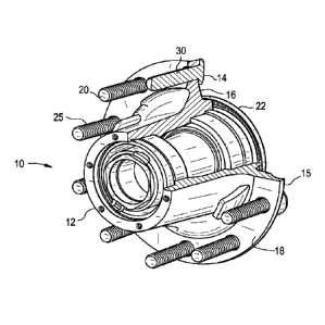
FIG. 1 is a perspective, partial cut away view of a prior art wheel hub.
FIG. 2 is a perspective view of a prior art wheel hub and components;
FIG. 2A is a side view of a prior art threaded fastener;
FIG. 3 is a perspective view of a wheel hub and components according to one
embodiment of the
45 present invention;
FIG. 4 is a perspective, partial cut away view of a wheel hub and components
according to one
2

CA 03084485 2020-04-22
WO 2019/084281
PCT/US2018/057537
embodiment of the present invention;
FIG. 5 is a perspective view of a wheel hub and components according to one
embodiment of the
present invention;
50 FIG. 6 is a perspective, exploded view of a wheel hub and components
according to one
embodiment of the present invention;
FIG. 7 is a perspective view of a wheel hub according to one embodiment of the
present
invention;
FIG. 8 is a side cut away view of a wheel hub according to one embodiment of
the present
55 invention;
FIG. 9 is a partial, side cut away view of a wheel hub according to one
embodiment of the
present invention;
FIG. 10 is a top view of a threaded fastener in accordance with one embodiment
of the present
invention;
60 FIG. 11 is a side view of a threaded fastener in accordance with one
embodiment of the present
invention;
FIG. 12 is a side cut away view of a threaded fastener in an opening in a
wheel hub flange in
accordance with one embodiment of the present invention, and
FIG. 13 is a top view of a threaded fastener in an opening in a wheel hub
flange in accordance
65 with one embodiment of the present invention.
DETAILED DESCRIPTION
FIG. 1 illustrates a prior art wheel retention system 10 according to one
embodiment of
the invention. System 10 includes a roughly bell-shaped wheel hub 12 having a
barrel portion
which attaches to an axleby bearings. A cylindrical opening 14, which may be
formed by a
3

CA 03084485 2020-04-22
WO 2019/084281
PCT/US2018/057537
70 drilling operation, is defined by an outer peripheral mounting flange 15
of the wheel hub 12.
Opening 14 extends from an inboard surface 16 to an outboard surface 18 of
wheel hub
mounting flange 15.
A connector, such as a threaded wheel bolt 20, is illustrated with the shank
22 at one end,
and a threaded portion 25 at an opposing end. Shank 22 is fitted into a
cylindrical opening 14 of
75 the wheel hub mounting flange 15. The bolt shank 22 extends through
opening 14. A wheel nut
(not shown) engages the bolt portion 25 having threads to mount a wheel and
tire on wheel hub
12. The bolt 20 has a head 30 with an undersurface 32 serving as a contact
surface with the
inboard surface 16 of wheel hub flange 15. Typically a plurality of openings
14 are equally
spaced around the periphery of the wheel hub mounting flange 15, each
receiving a bolt 20, with
80 the number of bolts depending upon the mounting system bolt circle
diameter.
A detailed view of a prior art wheel hub and threaded fastener are shown in
FIGs. 2 and 2A and
are described above.
FIGS. 3 and 4 illustrate an embodiment of wheel retention system 10 according
to the
present invention. As particularly shown, wheel hub mounting flange 15
includes an integral
85 bolt stop 31 adjacent each opening 14. Bolt stop 31 is seen to comprise
a radially inner facing
flat surface 36 that covers about 90 degrees of cylindrical opening 14. Bolt
stop 31 also is
comprised of an axially outer edge 32. Bolt stop 31 is seen to be integral
with and extend from
an outer radial edge of wheel hub flange 15.
In FIGs. 5 and 6, wheel hub 12 is seen with wheel hub mounting flange 15. Bolt
stop 31
90 is seen with inner facing flat surface 36 against which corresponding
flat surface 21 of bolt head
30 meshes or abuts.
4

CA 03084485 2020-04-22
WO 2019/084281
PCT/US2018/057537
Bolt 20 with shank 22 is seen to pass through cylindrical opening 14 with any
type of fit,
meaning there can be a clearance to an interference fit between the shank and
the opening. While
shank 22 may include serrations, it is meant to pass through opening 14 in a
little to no
95 interference manner. In sum, while bolt 20 with shank 22 is held in
opening 14, it is not
necessarily press fit to pass there through. Accordingly, there is little to
no stress on wheel hub
mounting flange 15 due to bolt 20 passing through opening 14.
However, bolt head 30 includes a flat section 21 that corresponds to about 90
degrees of
the circumference of bolt head 30. Bolt head flat section 21 meshes or abuts
flat surface 36 of
100 bolt stop 31. This meshing provides the rotational restriction for bolt
20 to allow wheel nuts to
be assembled thereon and accordingly hold the brake drum (if present) and
wheel to wheel hub
12.
Referring now to FIGs. 7, 8 and 9, detailed views of wheel hub 12 with bolt
stop 31 are
provided. As particularly shown, wheel hub mounting flange 15 includes an
integral bolt stop 31
105 adjacent each opening 14. Bolt stop 31 is seen to comprise a radially
inner facing flat surface 36
that covers about 90 degrees of cylindrical opening 14. Bolt stop 31 also is
comprised of an
axially outer edge 32. Bolt stop 31 is seen to be integral with and extend
from an outer radial
edge of wheel hub flange 15.
Referring now to FIGs. 10, 11, 12, and 13, threaded wheel bolt 20, is
illustrated with the
110 shank 22 at one end, and a threaded portion 25 at an opposing end. Bolt
head 30 includes a flat
section 21 that corresponds to about 90 degrees of the circumference of bolt
head 30. Bolt head
flat section 21 meshes or abuts flat surface 36 of bolt stop 31. This meshing
provides the
rotational restriction for bolt 20 to allow wheel nuts to be assembled on the
threaded section 25
and accordingly hold the brake drum (if present) and wheel to wheel hub 12.

Dessin représentatif
Une figure unique qui représente un dessin illustrant l'invention.
États administratifs

Pour une meilleure compréhension de l'état de la demande ou brevet qui figure sur cette page, la rubrique Mise en garde , et les descriptions de Brevet , États administratifs , Taxes périodiques et Historique des paiements devraient être consultées.

États administratifs

Titre Date
Date de délivrance prévu 2022-04-26
(86) Date de dépôt PCT 2018-10-25
(87) Date de publication PCT 2019-05-02
(85) Entrée nationale 2020-04-22
Requête d'examen 2020-04-22
(45) Délivré 2022-04-26

Historique d'abandonnement

Il n'y a pas d'historique d'abandonnement

Taxes périodiques

Dernier paiement au montant de 210,51 $ a été reçu le 2023-09-20


 Montants des taxes pour le maintien en état à venir

Description Date Montant
Prochain paiement si taxe générale 2024-10-25 277,00 $
Prochain paiement si taxe applicable aux petites entités 2024-10-25 100,00 $

Avis : Si le paiement en totalité n'a pas été reçu au plus tard à la date indiquée, une taxe supplémentaire peut être imposée, soit une des taxes suivantes :

  • taxe de rétablissement ;
  • taxe pour paiement en souffrance ; ou
  • taxe additionnelle pour le renversement d'une péremption réputée.

Les taxes sur les brevets sont ajustées au 1er janvier de chaque année. Les montants ci-dessus sont les montants actuels s'ils sont reçus au plus tard le 31 décembre de l'année en cours.
Veuillez vous référer à la page web des taxes sur les brevets de l'OPIC pour voir tous les montants actuels des taxes.

Historique des paiements

Type de taxes Anniversaire Échéance Montant payé Date payée
Enregistrement de documents 2020-04-22 100,00 $ 2020-04-22
Le dépôt d'une demande de brevet 2020-04-22 400,00 $ 2020-04-22
Requête d'examen 2023-10-25 800,00 $ 2020-04-22
Taxe de maintien en état - Demande - nouvelle loi 2 2020-10-26 100,00 $ 2020-09-18
Taxe de maintien en état - Demande - nouvelle loi 3 2021-10-25 100,00 $ 2021-09-21
Taxe finale 2022-03-30 305,39 $ 2022-02-02
Taxe de maintien en état - brevet - nouvelle loi 4 2022-10-25 100,00 $ 2022-09-22
Taxe de maintien en état - brevet - nouvelle loi 5 2023-10-25 210,51 $ 2023-09-20
Titulaires au dossier

Les titulaires actuels et antérieures au dossier sont affichés en ordre alphabétique.

Titulaires actuels au dossier
CONSOLIDATED METCO, INC.
Titulaires antérieures au dossier
S.O.
Les propriétaires antérieurs qui ne figurent pas dans la liste des « Propriétaires au dossier » apparaîtront dans d'autres documents au dossier.
Documents

Pour visionner les fichiers sélectionnés, entrer le code reCAPTCHA :


Pour visualiser une image, cliquer sur un lien dans la colonne description du document. Pour télécharger l'image (les images), cliquer l'une ou plusieurs cases à cocher dans la première colonne et ensuite cliquer sur le bouton "Télécharger sélection en format PDF (archive Zip)" ou le bouton "Télécharger sélection (en un fichier PDF fusionné)".

Liste des documents de brevet publiés et non publiés sur la BDBC .

Si vous avez des difficultés à accéder au contenu, veuillez communiquer avec le Centre de services à la clientèle au 1-866-997-1936, ou envoyer un courriel au Centre de service à la clientèle de l'OPIC.


Description du
Document 
Date
(yyyy-mm-dd) 
Nombre de pages   Taille de l'image (Ko) 
Abrégé 2020-04-22 2 75
Revendications 2020-04-22 4 107
Dessins 2020-04-22 7 173
Description 2020-04-22 5 193
Dessins représentatifs 2020-04-22 1 26
Traité de coopération en matière de brevets (PCT) 2020-04-22 1 97
Rapport prélim. intl. sur la brevetabilité reçu 2020-04-22 7 316
Rapport de recherche internationale 2020-04-22 1 50
Demande d'entrée en phase nationale 2020-04-22 11 506
Page couverture 2020-08-06 1 61
Certificat électronique d'octroi 2022-04-26 1 2 527
Demande d'examen 2021-05-21 6 256
Modification 2021-06-09 13 397
Revendications 2021-06-09 7 257
Dessins 2021-06-09 7 175
Enregistrer une note relative à une entrevue (Acti 2021-08-19 1 30
Modification 2021-08-19 5 224
Revendications 2021-08-19 7 268
Taxe finale 2022-02-02 4 88
Dessins représentatifs 2022-03-31 1 17
Page couverture 2022-03-31 1 49