Note: Descriptions are shown in the official language in which they were submitted.
CA 03102081 2020-11-30
WO 2019/245384
PCT/N02019/050131
1
TOOL FOR TIGHTENING NUT ON A BOLT TO FORM A FIXED CONNECTION
FIELD OF INVENTION
The invention relates to a tool for tightening nuts on bolts, where bolt and
nut are
used as fixing means.
BACKGROUND
Tools most known for such use are Fixed Wrenches and Spanner Wrenches that are
used where there are no given requirements on the tightening torque and
accuracy
of the tightening. But for example, something as common as wheel nuts on
vehicles
requires more accuracy, so here the last step of the tightening is done is by
means
of torque wrenches.
In machines and pipe connections in the offshore and process industries, the
requirements for accurate tightening of bolts are often very strict and are
performed according to procedures involving both lubricant and how to apply of
this
onto the threads and the narrow limits for the torque. Nevertheless, it turns
out
that different tension occurs in the bolts due to the variation in friction
between
threads and between nut and base material or washer which is typical used.
Some of these known bolt tension tools for tightening the bolts and nuts
together in
a fixed connection consist of hollow hydraulic cylinders with a mounting
surface in
the bottom, with a recessed and rotationally free device to retract the nut,
as well
as an external high-pressure oil pump. When the oil is pressed into the
cylinder, the
bolt is stretched with a force determined by the pressure and the nut is then
screwed on. Then the oil pressure is relieved, and the set is unscrewed for
use on
the next bolt. With this method one gets even and accurate tension in all the
bolts.
The application EP3126096 is describing a technology where the tool also
having a
tension rod which tensioning the bolt. The tension rod here has no simple
releasable link for replacing the pipe head. Nor has any integrated mechanism
been
provided for tightening the nut, which must be tightened and loosened manually
with a separate torque rod.
CA 03102081 2020-11-30
WO 2019/245384
PCT/N02019/050131
2
SUMMARY OF THE INVENTION
It is an object of the present invention to provide a tool which has all the
necessary
sequential functions and elements built into it and only need to replace a
nozzle
assembly to adapt the tool to different bolt and nut sizes, making the tool
time
efficient and easy to use in line with other hand tools. Said nozzle assembly
includes a tensioning shaft and pipe adapted to the particular size of the
bolt and
nut concerned. To operate in hazardous areas, the tool will preferably only
operate
with compressed air as a power supply in air-room facilities to avoids the
dangers
and disadvantages of external high-pressure hydraulic fittings such as hoses
and
connections.
The inventive tool will be suitable for mounting on remote controlled devices
such
as robots and underwater vehicles, usually referred to as ROVs s. Here the
power
supply will be hydraulics in the form of water or some type of oil or in the
combination. In this embodiment the handle will be replaced with a connector
and
trigger system suitable.
A preferred embodiment of the tool for tightening the nut on the bolt to form
the
fixed connection, includes a first motor, a bolt tensioner shaft with internal
threads
which connects to the bolt, wherein the bolt tensioner shaft is adapted to be
rotated
by the first motor, a locking claw connecting the bolt tensioner shaft to an
upper
hydraulic tensioner shaft a hydraulic piston attached to said hydraulic
tensioner
shaft, an oil pump supplying oil to the hydraulic piston wherein the hydraulic
piston
is adapted to extend and stretch the bolt when an oil pressure is introduced
from
the oil pump to the hydraulic piston. A second motor and a pipe which is
swivel-
connected axially to the bolt tensioner shaft for engaging the nut, wherein
the pipe
is adapted to be rotated by the second motor.
A more preferred embodiment also including a gear mechanism with first and
second gear wheel rotatable mounted on a common gear shaft, wherein the first
gear wheel is adapted to transfer rotational motion from the first fluid
driven motor
to the bolt tensioner shaft and the second gear wheel is adapted to transfer
rotational motion from the second fluid driven motor to the pipe.
CA 03102081 2020-11-30
WO 2019/245384
PCT/N02019/050131
3
An even more preferred embodiment including a display system with a
microprocessor connected to the said display system, and an oil pressure
sensor
connected to the microprocessor, wherein the pressure sensor is detecting the
oil
pressure delivered from the oil pump which is shown on the display.
Most preferred embodiment is further including a fluid pressure sensor
detecting
the fluid pressure delivered to the first and second fluid driven motors,
wherein the
first and second motors are powered by a fluid or electricity.
These objects are solved by a tool as disclosed in the appended claims.
BRIEF DESCRIPTION OF THE DRAWINGS
The invention will now be described in more detail and with reference to the
appended in which:
Fig.1 A showing a left side view of the tool.
Fig.1 B showing the tool underneath.
Fig.1 C showing a perspective of the of the tool.
Fig.2 A showing a section view of the cylinder house including the replaceable
nozzle.
Fig.2 B showing a sub assembly of the mechanism, including the replaceable
nozzle.
Fig.3 A showing a detail section of the pneumatic house.
Fig.3 B showing the detailed view of the motor house.
Fig.4 showing the schematics of the total system.
DETAILED DESCRIPTION OF THE DRAWINGS
Figure 1 A-B-C, showing the position of; a cap 1 mounted with bolts on top of
the
cylinder house for hydraulics 2. cylinder house for air-supply 3 mounted at
the rear
part of the tool, the middle plate 4 mounted between the said cylinder houses
2, 3
and the air motor house 5 which is the lowest part of the tool and housing the
motors.
The rear plate 6 bolted to the said cylinder house for hydraulics 2 thru the
said
cylinder house for pneumatics 3 and connects the handle 7 to the tool. Valve
house
8 is placed between the said cylinder houses 2, 3, including the operational
switch
CA 03102081 2020-11-30
WO 2019/245384
PCT/N02019/050131
4
which change the direction of rotation placed with handles on both side of the
tool and the Regulator for Maximum Pressure 11 for regulating the power supply
pressure where the wheel for regulating the pressure is placed on top right of
the
top plate 1. A stub 9 in the very bottom of the construction for direct
interface
5 towards the base material or a washer or the like.
A trigger 12 which open and close the valve regulating the power supply flow,
as
part of the handle 7, and a power supply coupler 13 which is the connection
between the tool and the power supply, and finally a display including a
microprocessor adapted to read and analyse sensor data coming from pressure
10 sensors in the power supply system and/or sensors in the hydraulic power
system.
Further in the cylinder house for hydraulics 2 a locking claw 25 is provided
for
enabling the replacement of the nozzle including the bolt tensioner shaft 26
which
connects to the bolt and the pipe 27 which rotates the nut.
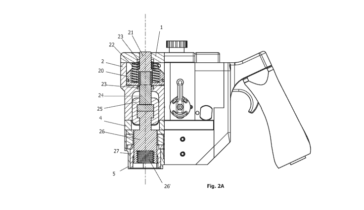
Figure 2 A-B, showing a detailed view of the said hydraulic cylinder house 2
and
every part visualized with numbering.
A hydraulic piston 20 including an 0-ring seal 20', capable of moving in
vertical
directions, housing Springs 22 providing positive down force. A hydraulic
shaft 21
is connected to the said Hydraulic Piston and is sealed both on the upper side
and
on the bottom side of the hydraulics with Seals 23. An upper hydraulic
tensioner
shaft 24 underneath and screwed into the said Hydraulic Piston connects the
upper
hydraulic system to a locking claw 25.
This said locking claw connects the said upper hydraulic tensioner shaft 24
with a
replaceable bolt tensioner shaft 26. Said bolt tensioner shaft has an inner
thread
26' which enables the Shaft 26 to be screwed onto a bolt and transfers the
force
from the tool to the said bolt. A standard sized pipe 27 with standard
hexagonal
interface 27' for the nut is swivel connected to the said shaft 26.
Figure 3 A-B, showing a detailed view of the pneumatic cylinder house 3, the
motor house 5 and every part visualized with numbering.
An air-driven piston 31 activating a Piston 33 which activates an Oil Pump 34'
capable of increasing or decreasing the hydraulic pressure acting on the said
CA 03102081 2020-11-30
WO 2019/245384
PCT/N02019/050131
hydraulic piston. A Return Spring 32 pushing the said air-driven piston back
to the
showed start position when no air pressure is acting on the said piston.
A Communicator Pin 36 for controlling the air flow acting on the said air-
driven
5 piston. An Inlet Valve 80' of check valve type, securing the flow. And
with a Valve
Plug 81 mounted to the top of the air supply cylinder house 3. And a flow turn
pin
84 for directing the air flow.
Figure 4, showing a function and connection diagram for the tool where the
1.0 .. operator first adjust the force wanted to stretch the bolts using the
wheel 11 on the
maximum pressure regulator (83'), and placing the tool on the bolt and
activate
the operational switch in a first position which activates the Air Motor 90'
to screw
the tension rod 24 onto the bolt threads at the same time as a fitted pipe 27
enters
the nut and turn it to enter the same bolt threads.
.. Then by actuating a Valve 12' via the trigger 12, the internal air-driven
hydraulic
pump 34' and start pressing oil into the hydraulic cylinder where a piston 20
pulls
the tension bar 24 and extends the bolt while the nut is simultaneously
actuated by
torque from the air motor 91'. When the predetermined tension for the bolt is
reached, the operational switch is moved to a second position whereby the air
.. motor 90' goes in reverse.
The trigger 12 is released, whereby the oil pump 34' stops and the oil
pressure is
released by the pressure relief valve 86' opening when the air pressure from
the
valve 12' is absent and the tool is unscrewed by the bolt and ready for the
next
bolt and nut.