Sélection de la langue

Search

Sommaire du brevet 3102081 

Énoncé de désistement de responsabilité concernant l'information provenant de tiers

Une partie des informations de ce site Web a été fournie par des sources externes. Le gouvernement du Canada n'assume aucune responsabilité concernant la précision, l'actualité ou la fiabilité des informations fournies par les sources externes. Les utilisateurs qui désirent employer cette information devraient consulter directement la source des informations. Le contenu fourni par les sources externes n'est pas assujetti aux exigences sur les langues officielles, la protection des renseignements personnels et l'accessibilité.

Disponibilité de l'Abrégé et des Revendications

L'apparition de différences dans le texte et l'image des Revendications et de l'Abrégé dépend du moment auquel le document est publié. Les textes des Revendications et de l'Abrégé sont affichés :

  • lorsque la demande peut être examinée par le public;
  • lorsque le brevet est émis (délivrance).
(12) Demande de brevet: (11) CA 3102081
(54) Titre français: OUTIL PERMETTANT DE SERRER UN ECROU SUR UN BOULON POUR FORMER UNE LIAISON FIXE
(54) Titre anglais: TOOL FOR TIGHTENING NUT ON A BOLT TO FORM A FIXED CONNECTION
Statut: Demande conforme
Données bibliographiques
Abrégés

Abrégé français

La présente invention se rapporte à un outil qui permet de serrer un écrou sur un boulon pour former une liaison fixe, et qui est constitué d'une pompe hydraulique à entraînement pneumatique transférant une pression d'huile à un vérin hydraulique avec un piston relié à un arbre qui, au moyen d'un moteur à entraînement pneumatique (90'), est amené à se visser sur les filets du boulon où l'écrou est relié à un second moteur à entraînement pneumatique (91') distinct qui visse l'écrou sur ledit boulon alors que le boulon est étiré.


Abrégé anglais

A Tool for tightening a nut on a bolt to form a fixed connection, consisting of an air-driven hydraulic pump which transfers oil pressure to a hydraulic cylinder with a piston connected to a shaft which by means of an air-driven motor (90') is caused to screw on the threads of the bolt where the nut is connected to a second separate 5 air-driven motor (91') that screws the nut on the said bolt as the bolt is stretched.

Revendications

Note : Les revendications sont présentées dans la langue officielle dans laquelle elles ont été soumises.


PCT/NO 2019/050 131 - 20.04.2020
CA 03102081 2020-11-30
6
Claims
1. A tool for tightening a nut on a bolt to form a fixed connection by
first stretching the
bolt with a set force with subsequent screwing on the nut for correct
prestress, wherein the
tool includes:
a first motor (90'),
a bolt tensioner shaft (26) with internal threads (26') which connects to the
bolt, wherein the
bolt tensioner shaft is adapted to be rotated by said first motor (90')
a hydraulic piston (20),
an oil pump (34') supplying oil to the hydraulic piston (20),
wherein the hydraulic piston is adapted to extend and stretch the bolt when an
oil pressure is
introduced from the oil pump (34') to the hydraulic piston (20),
a second motor (91'), and
a pipe (27) which is adapted to be rotated by the second motor,
characterized in that the hydraulic piston (20) is attached to a hydraulic
tensioner shaft (74),
wherein the hydraulic tensioner shaft (24) is connected to said bolt tensioner
shaft (76) by a
locking claw (25), and wherein the pipe (27) is swivel-connected axially to
the bolt tensioner
shaft (26) for engaging the nut.
2. A tool according to claim 1, further including a gear mechanism with
first and second
gear wheel rotatable mounted on a static common gear shaft, wherein the first
gear wheel is
adapted to transfer rotational motion from the first fluid driven motor (90')
to the bolt
tensioner shaft (26), and the second gear wheel is adapted to transfer
rotational motion from
the second fluid driven motor (91') to the pipe (27).
3. A tool according to claim 1 or 2, further including a display (14), a
microprocessor
connected to the display, an oil pressure sensor connected to the
microprocessor, wherein the
pressure sensor is detecting the oil pressure delivered from the oil pump
(34), which is shown
on the display.
4. A tool according to any of claims 1 to 3, further including a fluid
pressure sensor
detecting the fluid pressure delivered to the first and second fluid driven
motors (90', 91').
S. A tool according to clairn 1, wherein the first and second motors (90,
91') are powered
by a fluid or electricity.
AMENDED SHEET
Date recue/Date Received 2020-11-30

Description

Note : Les descriptions sont présentées dans la langue officielle dans laquelle elles ont été soumises.

CA 03102081 2020-11-30
WO 2019/245384
PCT/N02019/050131
1
TOOL FOR TIGHTENING NUT ON A BOLT TO FORM A FIXED CONNECTION
FIELD OF INVENTION
The invention relates to a tool for tightening nuts on bolts, where bolt and
nut are
used as fixing means.
BACKGROUND
Tools most known for such use are Fixed Wrenches and Spanner Wrenches that are
used where there are no given requirements on the tightening torque and
accuracy
of the tightening. But for example, something as common as wheel nuts on
vehicles
requires more accuracy, so here the last step of the tightening is done is by
means
of torque wrenches.
In machines and pipe connections in the offshore and process industries, the
requirements for accurate tightening of bolts are often very strict and are
performed according to procedures involving both lubricant and how to apply of
this
onto the threads and the narrow limits for the torque. Nevertheless, it turns
out
that different tension occurs in the bolts due to the variation in friction
between
threads and between nut and base material or washer which is typical used.
Some of these known bolt tension tools for tightening the bolts and nuts
together in
a fixed connection consist of hollow hydraulic cylinders with a mounting
surface in
the bottom, with a recessed and rotationally free device to retract the nut,
as well
as an external high-pressure oil pump. When the oil is pressed into the
cylinder, the
bolt is stretched with a force determined by the pressure and the nut is then
screwed on. Then the oil pressure is relieved, and the set is unscrewed for
use on
the next bolt. With this method one gets even and accurate tension in all the
bolts.
The application EP3126096 is describing a technology where the tool also
having a
tension rod which tensioning the bolt. The tension rod here has no simple
releasable link for replacing the pipe head. Nor has any integrated mechanism
been
provided for tightening the nut, which must be tightened and loosened manually
with a separate torque rod.

CA 03102081 2020-11-30
WO 2019/245384
PCT/N02019/050131
2
SUMMARY OF THE INVENTION
It is an object of the present invention to provide a tool which has all the
necessary
sequential functions and elements built into it and only need to replace a
nozzle
assembly to adapt the tool to different bolt and nut sizes, making the tool
time
efficient and easy to use in line with other hand tools. Said nozzle assembly
includes a tensioning shaft and pipe adapted to the particular size of the
bolt and
nut concerned. To operate in hazardous areas, the tool will preferably only
operate
with compressed air as a power supply in air-room facilities to avoids the
dangers
and disadvantages of external high-pressure hydraulic fittings such as hoses
and
connections.
The inventive tool will be suitable for mounting on remote controlled devices
such
as robots and underwater vehicles, usually referred to as ROVs s. Here the
power
supply will be hydraulics in the form of water or some type of oil or in the
combination. In this embodiment the handle will be replaced with a connector
and
trigger system suitable.
A preferred embodiment of the tool for tightening the nut on the bolt to form
the
fixed connection, includes a first motor, a bolt tensioner shaft with internal
threads
which connects to the bolt, wherein the bolt tensioner shaft is adapted to be
rotated
by the first motor, a locking claw connecting the bolt tensioner shaft to an
upper
hydraulic tensioner shaft a hydraulic piston attached to said hydraulic
tensioner
shaft, an oil pump supplying oil to the hydraulic piston wherein the hydraulic
piston
is adapted to extend and stretch the bolt when an oil pressure is introduced
from
the oil pump to the hydraulic piston. A second motor and a pipe which is
swivel-
connected axially to the bolt tensioner shaft for engaging the nut, wherein
the pipe
is adapted to be rotated by the second motor.
A more preferred embodiment also including a gear mechanism with first and
second gear wheel rotatable mounted on a common gear shaft, wherein the first
gear wheel is adapted to transfer rotational motion from the first fluid
driven motor
to the bolt tensioner shaft and the second gear wheel is adapted to transfer
rotational motion from the second fluid driven motor to the pipe.

CA 03102081 2020-11-30
WO 2019/245384
PCT/N02019/050131
3
An even more preferred embodiment including a display system with a
microprocessor connected to the said display system, and an oil pressure
sensor
connected to the microprocessor, wherein the pressure sensor is detecting the
oil
pressure delivered from the oil pump which is shown on the display.
Most preferred embodiment is further including a fluid pressure sensor
detecting
the fluid pressure delivered to the first and second fluid driven motors,
wherein the
first and second motors are powered by a fluid or electricity.
These objects are solved by a tool as disclosed in the appended claims.
BRIEF DESCRIPTION OF THE DRAWINGS
The invention will now be described in more detail and with reference to the
appended in which:
Fig.1 A showing a left side view of the tool.
Fig.1 B showing the tool underneath.
Fig.1 C showing a perspective of the of the tool.
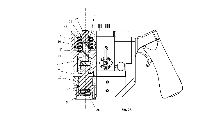
Fig.2 A showing a section view of the cylinder house including the replaceable
nozzle.
Fig.2 B showing a sub assembly of the mechanism, including the replaceable
nozzle.
Fig.3 A showing a detail section of the pneumatic house.
Fig.3 B showing the detailed view of the motor house.
Fig.4 showing the schematics of the total system.
DETAILED DESCRIPTION OF THE DRAWINGS
Figure 1 A-B-C, showing the position of; a cap 1 mounted with bolts on top of
the
cylinder house for hydraulics 2. cylinder house for air-supply 3 mounted at
the rear
part of the tool, the middle plate 4 mounted between the said cylinder houses
2, 3
and the air motor house 5 which is the lowest part of the tool and housing the
motors.
The rear plate 6 bolted to the said cylinder house for hydraulics 2 thru the
said
cylinder house for pneumatics 3 and connects the handle 7 to the tool. Valve
house
8 is placed between the said cylinder houses 2, 3, including the operational
switch

CA 03102081 2020-11-30
WO 2019/245384
PCT/N02019/050131
4
which change the direction of rotation placed with handles on both side of the
tool and the Regulator for Maximum Pressure 11 for regulating the power supply
pressure where the wheel for regulating the pressure is placed on top right of
the
top plate 1. A stub 9 in the very bottom of the construction for direct
interface
5 towards the base material or a washer or the like.
A trigger 12 which open and close the valve regulating the power supply flow,
as
part of the handle 7, and a power supply coupler 13 which is the connection
between the tool and the power supply, and finally a display including a
microprocessor adapted to read and analyse sensor data coming from pressure
10 sensors in the power supply system and/or sensors in the hydraulic power
system.
Further in the cylinder house for hydraulics 2 a locking claw 25 is provided
for
enabling the replacement of the nozzle including the bolt tensioner shaft 26
which
connects to the bolt and the pipe 27 which rotates the nut.
Figure 2 A-B, showing a detailed view of the said hydraulic cylinder house 2
and
every part visualized with numbering.
A hydraulic piston 20 including an 0-ring seal 20', capable of moving in
vertical
directions, housing Springs 22 providing positive down force. A hydraulic
shaft 21
is connected to the said Hydraulic Piston and is sealed both on the upper side
and
on the bottom side of the hydraulics with Seals 23. An upper hydraulic
tensioner
shaft 24 underneath and screwed into the said Hydraulic Piston connects the
upper
hydraulic system to a locking claw 25.
This said locking claw connects the said upper hydraulic tensioner shaft 24
with a
replaceable bolt tensioner shaft 26. Said bolt tensioner shaft has an inner
thread
26' which enables the Shaft 26 to be screwed onto a bolt and transfers the
force
from the tool to the said bolt. A standard sized pipe 27 with standard
hexagonal
interface 27' for the nut is swivel connected to the said shaft 26.
Figure 3 A-B, showing a detailed view of the pneumatic cylinder house 3, the
motor house 5 and every part visualized with numbering.
An air-driven piston 31 activating a Piston 33 which activates an Oil Pump 34'
capable of increasing or decreasing the hydraulic pressure acting on the said

CA 03102081 2020-11-30
WO 2019/245384
PCT/N02019/050131
hydraulic piston. A Return Spring 32 pushing the said air-driven piston back
to the
showed start position when no air pressure is acting on the said piston.
A Communicator Pin 36 for controlling the air flow acting on the said air-
driven
5 piston. An Inlet Valve 80' of check valve type, securing the flow. And
with a Valve
Plug 81 mounted to the top of the air supply cylinder house 3. And a flow turn
pin
84 for directing the air flow.
Figure 4, showing a function and connection diagram for the tool where the
1.0 .. operator first adjust the force wanted to stretch the bolts using the
wheel 11 on the
maximum pressure regulator (83'), and placing the tool on the bolt and
activate
the operational switch in a first position which activates the Air Motor 90'
to screw
the tension rod 24 onto the bolt threads at the same time as a fitted pipe 27
enters
the nut and turn it to enter the same bolt threads.
.. Then by actuating a Valve 12' via the trigger 12, the internal air-driven
hydraulic
pump 34' and start pressing oil into the hydraulic cylinder where a piston 20
pulls
the tension bar 24 and extends the bolt while the nut is simultaneously
actuated by
torque from the air motor 91'. When the predetermined tension for the bolt is
reached, the operational switch is moved to a second position whereby the air
.. motor 90' goes in reverse.
The trigger 12 is released, whereby the oil pump 34' stops and the oil
pressure is
released by the pressure relief valve 86' opening when the air pressure from
the
valve 12' is absent and the tool is unscrewed by the bolt and ready for the
next
bolt and nut.

Dessin représentatif
Une figure unique qui représente un dessin illustrant l'invention.
États administratifs

2024-08-01 : Dans le cadre de la transition vers les Brevets de nouvelle génération (BNG), la base de données sur les brevets canadiens (BDBC) contient désormais un Historique d'événement plus détaillé, qui reproduit le Journal des événements de notre nouvelle solution interne.

Veuillez noter que les événements débutant par « Inactive : » se réfèrent à des événements qui ne sont plus utilisés dans notre nouvelle solution interne.

Pour une meilleure compréhension de l'état de la demande ou brevet qui figure sur cette page, la rubrique Mise en garde , et les descriptions de Brevet , Historique d'événement , Taxes périodiques et Historique des paiements devraient être consultées.

Historique d'événement

Description Date
Inactive : Lettre officielle 2024-03-28
Exigences quant à la conformité - jugées remplies 2023-06-28
Paiement d'une taxe pour le maintien en état jugé conforme 2023-06-28
Représentant commun nommé 2021-11-13
Inactive : Page couverture publiée 2021-01-06
Lettre envoyée 2020-12-22
Exigences applicables à la revendication de priorité - jugée conforme 2020-12-14
Demande reçue - PCT 2020-12-14
Inactive : CIB en 1re position 2020-12-14
Inactive : CIB attribuée 2020-12-14
Demande de priorité reçue 2020-12-14
Déclaration du statut de petite entité jugée conforme 2020-11-30
Exigences pour l'entrée dans la phase nationale - jugée conforme 2020-11-30
Demande publiée (accessible au public) 2019-12-26

Historique d'abandonnement

Il n'y a pas d'historique d'abandonnement

Taxes périodiques

Le dernier paiement a été reçu le 2023-06-28

Avis : Si le paiement en totalité n'a pas été reçu au plus tard à la date indiquée, une taxe supplémentaire peut être imposée, soit une des taxes suivantes :

  • taxe de rétablissement ;
  • taxe pour paiement en souffrance ; ou
  • taxe additionnelle pour le renversement d'une péremption réputée.

Les taxes sur les brevets sont ajustées au 1er janvier de chaque année. Les montants ci-dessus sont les montants actuels s'ils sont reçus au plus tard le 31 décembre de l'année en cours.
Veuillez vous référer à la page web des taxes sur les brevets de l'OPIC pour voir tous les montants actuels des taxes.

Historique des taxes

Type de taxes Anniversaire Échéance Date payée
Taxe nationale de base - petite 2020-11-30 2020-11-30
TM (demande, 2e anniv.) - petite 02 2021-06-21 2021-06-16
TM (demande, 3e anniv.) - petite 03 2022-06-20 2022-06-17
TM (demande, 4e anniv.) - petite 04 2023-06-20 2023-06-28
Surtaxe (para. 27.1(2) de la Loi) 2023-06-28 2023-06-28
Titulaires au dossier

Les titulaires actuels et antérieures au dossier sont affichés en ordre alphabétique.

Titulaires actuels au dossier
PATENTEC QUICKDRIVE AS
Titulaires antérieures au dossier
HILBERG INGE KAROLIUSSEN
Les propriétaires antérieurs qui ne figurent pas dans la liste des « Propriétaires au dossier » apparaîtront dans d'autres documents au dossier.
Documents

Pour visionner les fichiers sélectionnés, entrer le code reCAPTCHA :


Pour visualiser une image, cliquer sur un lien dans la colonne description du document. Pour télécharger l'image (les images), cliquer l'une ou plusieurs cases à cocher dans la première colonne et ensuite cliquer sur le bouton "Télécharger sélection en format PDF (archive Zip)" ou le bouton "Télécharger sélection (en un fichier PDF fusionné)".

Liste des documents de brevet publiés et non publiés sur la BDBC .

Si vous avez des difficultés à accéder au contenu, veuillez communiquer avec le Centre de services à la clientèle au 1-866-997-1936, ou envoyer un courriel au Centre de service à la clientèle de l'OPIC.


Description du
Document 
Date
(aaaa-mm-jj) 
Nombre de pages   Taille de l'image (Ko) 
Revendications 2020-11-29 1 93
Abrégé 2020-11-29 2 77
Description 2020-11-29 5 198
Dessins 2020-11-29 4 218
Dessin représentatif 2020-11-29 1 38
Courtoisie - Lettre du bureau 2024-03-27 2 188
Courtoisie - Lettre confirmant l'entrée en phase nationale en vertu du PCT 2020-12-21 1 595
Courtoisie - Réception du paiement de la taxe pour le maintien en état et de la surtaxe 2023-06-27 1 420
Rapport prélim. intl. sur la brevetabilité 2020-11-30 9 768
Demande d'entrée en phase nationale 2020-11-29 8 324
Déclaration 2020-11-29 2 32
Traité de coopération en matière de brevets (PCT) 2020-11-29 3 114
Rapport de recherche internationale 2020-11-29 3 74