Sélection de la langue

Search

Sommaire du brevet 1262289 

Énoncé de désistement de responsabilité concernant l'information provenant de tiers

Une partie des informations de ce site Web a été fournie par des sources externes. Le gouvernement du Canada n'assume aucune responsabilité concernant la précision, l'actualité ou la fiabilité des informations fournies par les sources externes. Les utilisateurs qui désirent employer cette information devraient consulter directement la source des informations. Le contenu fourni par les sources externes n'est pas assujetti aux exigences sur les langues officielles, la protection des renseignements personnels et l'accessibilité.

Disponibilité de l'Abrégé et des Revendications

L'apparition de différences dans le texte et l'image des Revendications et de l'Abrégé dépend du moment auquel le document est publié. Les textes des Revendications et de l'Abrégé sont affichés :

  • lorsque la demande peut être examinée par le public;
  • lorsque le brevet est émis (délivrance).
(12) Brevet: (11) CA 1262289
(21) Numéro de la demande: 1262289
(54) Titre français: OUTIL D'INSERTION/EXTRACTION DE CIRCUIT INTEGRE
(54) Titre anglais: IC INSERTION/EXTRACTION TOOL
Statut: Périmé et au-delà du délai pour l’annulation
Données bibliographiques
(51) Classification internationale des brevets (CIB):
  • H05K 03/32 (2006.01)
  • B25B 09/02 (2006.01)
  • B25B 27/02 (2006.01)
  • H05K 13/04 (2006.01)
(72) Inventeurs :
  • CARLSON, ROBERT L. (Etats-Unis d'Amérique)
  • MURGLIN, JOSEPH G. (Etats-Unis d'Amérique)
(73) Titulaires :
  • AMERICAN TELEPHONE & TELEGRAPH COMPANY
(71) Demandeurs :
  • AMERICAN TELEPHONE & TELEGRAPH COMPANY (Etats-Unis d'Amérique)
(74) Agent: KIRBY EADES GALE BAKER
(74) Co-agent:
(45) Délivré: 1989-10-10
(22) Date de dépôt: 1987-07-30
Licence disponible: S.O.
Cédé au domaine public: S.O.
(25) Langue des documents déposés: Anglais

Traité de coopération en matière de brevets (PCT): Non

(30) Données de priorité de la demande:
Numéro de la demande Pays / territoire Date
897,230 (Etats-Unis d'Amérique) 1986-08-18

Abrégés

Abrégé anglais


ABSTRACT OF THE DISCLOSURE
A tool for insertion and extraction of a packaged
IC to and from a socket includes a pair of flexible,
parallel arms joined at two ends by a "U" shaped portion.
The free ends of the two arms when moved towards each other
are adapted to grip the IC at opposite ends and allow a
rocking motion to be applied to loosen the pins of the IC
within the socket and then for a lifting force to be applied
to remove the IC from the socket, all with minimum distortion of
the pins. A plunger having a base which is positioned and is
free to move between the two parallel walls within the "U" is
used to insert an IC into its socket. The IC is positioned
between the two walls of the "U" with the pins of the IC
pointing outwards and the surface opposite the pins in contact
with the base of the plunger. The IC is retained within the
"U" by a predetermined interference fit between the walls and
the IC. The tool positions the IC over the socket and a
downward force is applied to the plunger to push the IC out of
the "U" portion and into the socket.

Revendications

Note : Les revendications sont présentées dans la langue officielle dans laquelle elles ont été soumises.


Claims:
1. A tool for inserting an IC pack, having a
plurality of pins extending from one of its surfaces,
into a socket having a plurality of openings adapted to
receive the pins, and for extracting the IC pack from
the socket, the tool comprising:
means for inserting the IC pack into the socket
including:
a "U" shaped portion;
a plunger having a substantially rectangular base
slidably mounted within the "U" shaped portion;
the "U" shaped portion adapted to accept the IC
pack between the two walls and retain it by frictional
force between the walls and the IC pack, which is
inserted into the "U" shaped portion with the pins
pointing outward and the surface of the IC pack opposite
the pins in contact with the base;
means for moving the base to push the IC pack out
of the "U" shaped portion and into the socket; and
means for extracting the IC pack from the socket
including:
a pair of flexible, parallel arms extending from
said "U" shaped portion, each arm a mirror image of the
other; and
means located at the free end of each of the arms
for gripping the IC pack at opposite ends thereby
enabling a rocking motion to be applied to the IC pack
to loosen the pins in the socket and then for a lifting
force to be applied to extract the IC pack from the
socket.
2. A tool in accordance with claim 1 wherein the means
for moving the base includes:
a stem having a substantially uniform cross section
extending from one of the major surfaces of the base;
the "U" shaped portion having an aperture adapted
to slidably accept the stem; and
means for retaining the stem within the aperture.

3. A tool in accordance with claim 2 wherein the means
of retaining the stem within the aperture in the "U"
includes:
the stem portion having a free end with a cross
section which is substantially smaller then the cross
section of the remainder of the stem;
a pair of flexible tabs extending in an out and
downward direction from the free end of the stem such
that when the free end of the stem is inserted into the
aperture in the "U", the tabs are pushed towards the
center line of the stem allowing the free end to pass
through the opening and allow the remainder of the stem
to enter the aperture, and wherein the tabs after
passing through the aperture, spring back to their
normal position extending over the edges of the aperture
and thus retain the stem within the aperture.
4. A tool for inserting an IC pack, having a plurality
of pins extending from one of its surfaces, into a
socket having a plurality of openings adapted to receive
the pins, and for extracting the IC pack from the
socket, the tool comprising:
means for inserting the IC pack into the socket
including:
a "U" shaped portion;
a plunger having a substantially rectangular base
slidably mounted within the "U" shaped portion;
the "U" shaped portion adapted to accept the IC
pack between the two walls and retain it by frictional
force between the walls and the IC pack, which is
inserted into the "U" shaped portion with the pins
pointing outward and the surface of the IC pack opposite
the pins in contact with the base;
means for moving the base to push the IC pack out
of the "U" shaped portion and into the socket including;
a stem having a substantially uniform cross section
extending from one of the major surfaces of the base;
the "U" shaped portion having an aperture adapted
to slidably accept the stem;

means for retaining the stem within the aperture
including:
the stem portion having a free end with a cross
section which is substantially smaller than the cross
section of the remainder of the stem;
a pair of flexible tabs extending in an out and
downward direction from the free end of the stem such
that when the free end of the stem is inserted into the
aperture in the "U", the tabs are pushed toward the
center line of the stem allowing the free end to pass
through the opening and allow the remainder of the stem
to enter the aperture, and wherein the tabs after
passing through the aperture, spring back to their
normal position extending over the edges of the aperture
and thus retain the stem within the aperture; and
means for extracting the IC pack from the socket.
5. A tool in accordance with claim 4 wherein the means
for extracting the IC pack from the socket includes:
a pair of flexible, parallel arms extending from
said "U" shaped portion, each arm a mirror image of the
other; and
means located at the free end of each of the arms
for gripping the IC pack at opposite ends thereby
enabling a rocking motion to be applied to the IC pack
to loosen the pins in the socket and then for a lifting
force to be applied to extract the IC pack from the
socket.
6. A tool in accordance with claim 1 or 5 wherein the
means for gripping the IC pack includes:
a first projection extending from the free end of
each arm towards the opposite arm;
a second projection parallel to the first proj-
ection and a predetermined distance away from the first
projection extending a distance farther than the first
projection towards the other arm, wherein the second
projection has a surface adapted to contact the surface
of the IC pack located opposite the surface having the
pins extending therefrom, and the first projection is
adapted to contact the surface from which the pins extend.

Description

Note : Les descriptions sont présentées dans la langue officielle dans laquelle elles ont été soumises.

~26~
--1--
1 TITLE
IC InsertLon/Extraction Tool
DESCRIPTION
TECHNICAL FIELD
This invention relates to a tool, and more
particularly to a combination tool, for inserting and/or
extracting integrated circuit (IC) packs into or from a
socket or similar type of support.
BACKGROUND ~RT
Present day electronic equipment utilizes a great
number of IC packs (packaged integrated circuit chips).
Typically the IC packs are plugged into sockets mounted on
printed circuit boards. The IC s are often removed and
reinserted for a number of reasons such as testing, program
changes, etc~ A typical dual-in-line IC pack contains 24 to
40 pins, each pin being approximately 15 mm~ wlde and 36 to
50 mm. long. The pins of these IC s are very fragile and
may easily be bent or deformed during the IC removal or
insertion process. Thus to remove or insert such an IC pack
from or into a socket, a great deal of time consuming care
must be taken to prevent pin damage.
A number oE commercially available devices solve
this problem by extracting or inserting the IC s in a
controlled, uniform manner in order to minimize pin
deformation~ These devices, however, are generally large,
complex, cumbersome, difficult to manufacture and thus
expensive. Typical devices are shown in US patents
Carlson 2-4

--2--
1 4,172,317 and 4~215,~68. ~nother disadvantage of
cor~merclally avallable devlces is that each is designed to
perform ~ust one function, e.g. either extract or insert an
IC but not perform both functions~
DISCLOSURE OF THE INVENTION
In accordance with the present inventlon, we
provlde a tool for insertion and extraction of an IC pack
to an from a socket, which tool includes two flexible,
parallel ar~s extendlng from a "U" shaped portion. The free
ends of each arm have projections extending towards the
opposite arm adapted to grip the IC pack at its opposite
ends when the ar~s are moved towards each other. A rocking
motion applied to the IC loosens its pins within the socket
and combined with a lifting force removes it from the
socket~
The tool further includes a plunger having a
substantially rectangular base which is positioned and is
free to move between the two parallel walls of the "U"
portion. An IC paclc to be inserted into a socket is
positioned between the two parallel walls with the pins at
opposite sides of the IC pack pointing downward and the
surface of the I~ pack opposite the pins mating with the
base of the plunger. The IC pack is retained within the "U"
portion by an interference fit between the walls and the IC
pack and the pins at opposite sides of the IC pack are
deflected by the walls to a distance apart corresponding to
distance separating corresponding openings in ~he socket.
The tool positions the IC pack over the socket and a
Carlson 2-4

~2~.,,~
--3--
I downward force applied to the plunger pushes the IC pack out
of the "U" portlon until all the plns oE the IC pack are
seated within the socket.
THE DRAWING
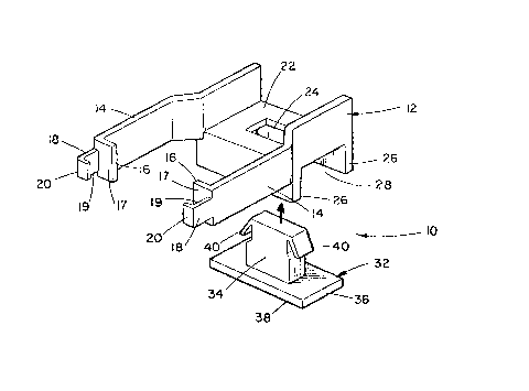
Figure 1 is an exploded perspective view of the
insertion/extraction tool before assembly.
Figure 2 is a bottom plan view of the assembled
tool shown in figure 1.
Figure 3 is a sectional view taken along line 3-3
of figure 2.
Figure 4 is a sectional view taken along line 4-4
of figure 20
Figure 5 is a perspective view of the tool
illustrating the manner in which the tool is used to extract
an IC pack from a socket~
Figure 6 is a perspective view illustrating the
manner in which the tool is u~ed to in~ert an IC pack into a
socket.
DETAILED DESCRIPTION
Referring now to the drawing in detall and
specifically to Figure 1, there is shown an exploded
perspective view of a tool 10 for inserting and extracting
an IC pack 50 to and from a æocket 52 ~shown in Figs. 5 and
6). Tool 10, 6hown in Fig. 1 before assembly, has a main
25 body portion 12 and a plunger portion 32. Both the body 12
and the plunger 32 may be manufactured by an injection
molding process from a thermal setting type of plastic
materlal. When body 12 and plunger 32 are assembled, as
Carlson 2-4

~L2~L
--4--
I shown ln Figures 2, 3 and 4, the plunger 32 becomes an
integral part of the body 12.
The main body portion 12 has a pair of flexible,
parallel arms 14 extending from a bridge portion 22 ~oining
the two arms. The two arms 14 are each a mirror image of
the other and each has inwardly directed projections 16 and
200 Projections 16 and 20 are parallel to each other and are
located a distance apart which i9 greater than the height of
the IC pack 50 to be removed. ProJection 16 is
approximately twice as long as pro~ection 20 and has a flat
surface 17 which is the width of the IC pack and is adjacent
to pro~ection 20. The width and thickness of pro~ection 20
is such that it is accomodated by an openlng 53 which exLsts
between the ends of the IC pack 50 and its socket 52. The
bridge portion 22 has a rectangular aperture 24 and a pair
of opposed wall portions 28 extendlng downward, the wall
portions 28 and the bridge 22 forming a "~" shaped opening
28.
The plunger 32 has a rectangular base 36 adapted
to slidably move within the "U" shaped opening 28. A
rectangular stem 34 extends from one of the ma~or Rurfaces
of the base 36 and is adapted to slidably move within the
aperture 24. The free end of the stem 34 terminates in a
rectangular section which has a smaller cross section than
the stem portion attached to the base 3So A pair of flexlble
tabs 40 extend in an out and downward sloping direction from
two sides of the free end of the stem 34 past the base of
the stem 34.

--5--
1 A~semhly of the tool 10 is accomplished by
inserting the stem portion 34 of the plunger 32 into the
aperture 24 as illustrated in Figure 1. Tabs 40 when in
normal rest position extend beyond the elongated aperture
24, as shown in Figure 4. Since the tabs are flexible,
during the ~nsertion of the stem 34 into the aperture 24
tabs 40 are compressed inward toward the center line of stem
34 allowing the free end of the stem 34 to pass through the
aperture 24 and then for the remainder oE the stem to enter
the aperture 24. Once the tabs 40 pass through the aperture
24, they spring back to their normal rest positlon retaining
stem 34 in the aperture 24. The stem 34 is o a length such
that when the tabs 40 contact the bridge portion 22, as
shown in ~igures 3 and 4, the bottom surface 38 of the base
36 is substantially flush with the free ends of the wall
portions 26. The distance between the opposing walls 26 is
slightly greater than the width of the base 36 allowing
plunger 32 free movement within the "U" shaped opening.
~igure S illustrates the manner Ln which tool 10
ls used to remove the IC pack 50 having a plurality of pins
54 located at opposite sides of the pack from the socket 52
which ls secured to a circuit board (not shown). Socket 52
has a plurality of openings 55 located along each side of
the socket arranged to accomodate the pins 54. The flat
portions 17 of pro~ections 16 of arms 14 are placed on the
upper surface of the IC pack 50 at both ends. By applying a
force by two fingers of a hand, the arms 14 are moved
towards each other until surfaces 19 of fingers 18 firmly
Carlson 2-4

: ~21E~,2~
-6~
1 engage both ends of the IC pack 50. During this tl~e,
p~ojections 20 enter openings 53 located between the IC pack
50 and the socket 52 engaging the bottom surface of the IC
pack 50. Once this is accomplished, a slight back and forth
rocking motion is initlated about the major axis of the IC
pack. The rocking motion loosens the pins of the IC pack 50
within the socket 52, and once the pins have been loosened,
a straight upward pulling motion extracts the IC pack 50
from the ~ocket 52.
Figure 6 illustrates a method for inserting the IC
pack 50 into the socket 52. Initially, the IC pack 50 is
placed in the "U" shaped portion 28 until it is fully seated
against the surface 38 of the base 36 of the plunger 32 with
the pins of the pack proiecting outwardly. The space
between the walls 26 of the "U" shaped portion 28 is
determined by the size of an IC pack which tool 10 is
designed to accomodate. The spacing is such that when an IC
pack is placed in the "U" shaped portion, there is
sufficient frlction between the IC pack and walls 26 to
retaln the IC pack within the "U" shaped portion 28 until a
force F is applied to plunger 32 to overcome the frictional
holding force. The height of the walls 26 is such that when
the IC pack 50 is within the "U" in contact with base 36,
and the base 36 is pushed against the bridge section 22, a
ma~or portion of pins 54 are within the "U" shaped opening.
The pins 54 are thereby aligned parallel to the walls 26 and
the distance betwe~n the pins 54, located at opposite sides
of the IC pack 50, is substantially equal to the distance
between openings 55 located along each side of socket 52.
Carlson 2-4

l between openings 55 located along each slde of socket 52.
The tool lO is placed over the socket 52 aligning the pins
54 of the IC pack 50 wlth correspondlng openingæ 55 in the
socket 52. Force F is then applied to stem 34 of the
5 plunger 32 in the di.rect:Lon oE arrow until the pins 54 of
the IC device 50 are fully seated in their respective
openings 55 of the socket 52.
Carlson 2-4

Dessin représentatif
Une figure unique qui représente un dessin illustrant l'invention.
États administratifs

2024-08-01 : Dans le cadre de la transition vers les Brevets de nouvelle génération (BNG), la base de données sur les brevets canadiens (BDBC) contient désormais un Historique d'événement plus détaillé, qui reproduit le Journal des événements de notre nouvelle solution interne.

Veuillez noter que les événements débutant par « Inactive : » se réfèrent à des événements qui ne sont plus utilisés dans notre nouvelle solution interne.

Pour une meilleure compréhension de l'état de la demande ou brevet qui figure sur cette page, la rubrique Mise en garde , et les descriptions de Brevet , Historique d'événement , Taxes périodiques et Historique des paiements devraient être consultées.

Historique d'événement

Description Date
Inactive : CIB de MCD 2006-03-11
Le délai pour l'annulation est expiré 2004-10-12
Lettre envoyée 2003-10-10
Accordé par délivrance 1989-10-10

Historique d'abandonnement

Il n'y a pas d'historique d'abandonnement

Historique des taxes

Type de taxes Anniversaire Échéance Date payée
Annulation de la péremption réputée 2002-10-10 1997-08-27
TM (catégorie 1, 8e anniv.) - petite 1997-10-10 1997-08-27
Annulation de la péremption réputée 2002-10-10 1998-09-24
TM (catégorie 1, 9e anniv.) - petite 1998-10-13 1998-09-24
TM (catégorie 1, 10e anniv.) - petite 1999-10-11 1999-09-20
Annulation de la péremption réputée 2002-10-10 1999-09-20
TM (catégorie 1, 11e anniv.) - petite 2000-10-10 2000-09-15
Annulation de la péremption réputée 2002-10-10 2000-09-15
Annulation de la péremption réputée 2002-10-10 2001-09-20
TM (catégorie 1, 12e anniv.) - petite 2001-10-10 2001-09-20
Annulation de la péremption réputée 2002-10-10 2002-09-19
TM (catégorie 1, 13e anniv.) - petite 2002-10-10 2002-09-19
Titulaires au dossier

Les titulaires actuels et antérieures au dossier sont affichés en ordre alphabétique.

Titulaires actuels au dossier
AMERICAN TELEPHONE & TELEGRAPH COMPANY
Titulaires antérieures au dossier
JOSEPH G. MURGLIN
ROBERT L. CARLSON
Les propriétaires antérieurs qui ne figurent pas dans la liste des « Propriétaires au dossier » apparaîtront dans d'autres documents au dossier.
Documents

Pour visionner les fichiers sélectionnés, entrer le code reCAPTCHA :


Pour visualiser une image, cliquer sur un lien dans la colonne description du document. Pour télécharger l'image (les images), cliquer l'une ou plusieurs cases à cocher dans la première colonne et ensuite cliquer sur le bouton "Télécharger sélection en format PDF (archive Zip)" ou le bouton "Télécharger sélection (en un fichier PDF fusionné)".

Liste des documents de brevet publiés et non publiés sur la BDBC .

Si vous avez des difficultés à accéder au contenu, veuillez communiquer avec le Centre de services à la clientèle au 1-866-997-1936, ou envoyer un courriel au Centre de service à la clientèle de l'OPIC.


Description du
Document 
Date
(aaaa-mm-jj) 
Nombre de pages   Taille de l'image (Ko) 
Abrégé 1993-09-13 1 22
Revendications 1993-09-13 3 133
Dessins 1993-09-13 2 51
Description 1993-09-13 7 187
Dessin représentatif 2001-04-18 1 11
Avis concernant la taxe de maintien 2003-12-07 1 174
Taxes 1996-08-19 1 64
Taxes 1995-09-14 1 63
Taxes 1992-08-26 1 56
Taxes 1994-08-31 1 71
Taxes 1993-08-16 1 35
Taxes 1991-09-23 1 35