Note : Les descriptions sont présentées dans la langue officielle dans laquelle elles ont été soumises.
~Ç~ J i'-~39
TWO-COMPONENT MEDICATION SYRINGE ASSEM~EY
BACKGRO~ND OF THE INVENTION
1. Field of the Invention. The present
invention relates to a syringe and more particu-
larly concerns a two-component medication syringe.
2. Description of the Prior Art. Some in-
S jectable medications have rapid loss of potency
when they are in their ready-to-use form. In ordcr
to protect against the short shelf life of thes~
medications, many of them are supplied in two
components, and they are mixed at the time of use.
Two-component medication is commonly available in
two vials with pierceable stoppers. A first vial
typically contains sterile water and the second
vial contains the active ingredients which may b~
in lyophilized form. To prepare the medication for
use, the user pierces the stopper of the vial
containing the water with a sterile syringe and
-needle assembly and withdraws the water into the
syringe. The needle is then removed from the first
vial and inserted into the second vial. Watee i~
injected into this vial to mix with the lyophilizc(l
medication. The mixed medication is ~hen withdrawn
into the syringe for injection. When the injection
is to be made into a vein, it is common practice to
~ 39
insert the needle into the patient and to withdraw
the plunger rod slightly from the syringe barrel,
If the needle is in a vein, a slight amount of
blood will be drawn into the syringe, The visual
sighting of the blood verifies that the nccdle is
in a vein, This procedure is called tl~e vein
indication test, AlSo, when injection of medica-
tion into a vein or artery is not desirable, the
vein indication test can be used to assure that t'ne
hypodermic needle is not in a vein or artery.
The above recited known components present
problems with respect to sterility since only the
interior of the medication Yial is sterile and
bacteria from the exterior of the vials and the
environment may be introduced into the mcdication
during the mixing procedure. Also, at the areas
where the cylindrical surfaces of the lumen of the
hypodermic needle intersect the planes of its
ground point, there are formed sharp edges that can
potentially cut pieces of the rubber vial stopper
away as the needle penetrates therein, These
pieces of rubber represent a potential problem i~
they pass alony with the liquid medication into the
patient's body. Further, cost is high since two
separate sterile containers and a sterile syring~
are normally required.
Brown (U,S. Patent No. 2,607,344) teaches
placing both components of the medication in a
glass tube where the components are separated by a
stopper with a piston stopper sealing the end of
the tube containing a liquid component and a
flanged pierceable stopper sealing the end of th~
tube containing a powder component. Also, within
the powder containing compartment, bounded by the
~ 39
-3~ p~1
stopper and the pierceable stopper, thcre is a
longitudinally positioned groove projecting radi-
ally outwardly enlarging the inside diameter of the
glass tubing. The groove is longer than the
5 stopper so that when the stopper is positioned
within the section of the tube containing the
groove, liquid can flow around the stopper through
the groove. Also provided is a separate barrel
having an open proximal end adapted to accept the
10 glass tube assembly and a distal end with a wall
containing a cannula with opposed points. One end
of the cannula projects into the barrel, and the
other end projects outwardly away from the distal
end of the barrel. In use, the tube assembly is
15 inserted into the barrel so that the portion o the
cannula inside the barrel penetrates the pierceable
stopper establishing fluid communication between
the interior of the tube and the atmosphere. Then
the piston stopper is forced inwardly pushing the
20 liquid component of the medication and the stopper
toward the distal end of the barrel. When the
stopper is positioned within the bypass, the liquid
component flows around the stopper through the
bypass to mix with the powder component. To
25 perform the vein indication test, the tube is
withdrawn to terminate fluid communication with the
cannula and then the outwardly facing portion of
the cannula is inserted into the patient. Since
the flange of the pierceable stopper is larger than
30 the inside diameter of the barrel, further with-
drawal of the tube from the barrel creates a
reduced pressure zone between the exterior end o
the pierceable stopper and the cannula causing
blood to flow from the cannula into the barrel,
1~ ~39
-4~
outside of the tube assembly, if the cannula is
lodged in a vein.
Genese, in U.S. Patent NUmber 4,226,236,
teaches placing a liquid diluent and a solid
medicament in a syringe barrel wherein the liquid
diluent is contained between two stoppers and the
solid medication is contained between one of the
aforementioned stoppers and a hydrophobic filter
which Genese suggests will not allow liquid to pass
therethrough This syringe contains an outwardly
projecting bypass on the side of the barrel To
mix the medicament and the diluent the user removes
a ferrule and the closure cap on the distal end of
the syringe assembly and then pushes the plunger
lS rod, which is attached to the first stopper,
inwardly. The movement of the first stopper forces
the diluent and the intermediate stopper in a
forward direction until the intermediate stopper is
positioned in the area of the bypass, and the
diluent is then forced around the intermediate
stopper through the bypass and onto the solid
medicament. It appears that when the diluent
contacts the entire surface of the hydrophobic
filter, no air or water is permitted to pass and,
further, that whatever air remains in the syringe
after the diluent contacts the hydrophobic filter
is trapped within the syringe and cannot escape.
At this point, Genese teaches that the syringe
is to be shaken to cause mixing oi- the two compo-
nents. To use this syringe, a slidably mountedhollow piercing member is moved reaewardly to
puncture the hydrophobic filter and to allow fluid
communication between the interior of the syringe
barrel and the interior of the hollo~ piercing
~ 39
--5--
member. The distal end of the slidablc piercin~
member is shaped to allow attachment of a hypo-
dermic needle assembly. With the hypodermic necdlc
assembly attached, the remaining air and mi%ec3
medication can be expelled from the syringe
Brown, in U.S. Patent Number 2,717,601 teache~
an ampule for use as part of a hypodermic syringe.
The ampule includes a tubular ampule body with its
proximal end closed by a piston-type stopper and
its distal end closed by a stopper. Between thc
ends of the ampule body a pair of axially extending
grooves is formed in the wall thereof. A floating
partition stopper is contained within the bore o~
the ampule on the proximal side of the grooves.
quantity of liquid diluent is contained in a first
compartment which is defined by the space in thc
tube between the piston-type stopper and the
floating partition stopper. A dry medication is
contained in a second compartment which is de~ined
by the space between the floating partition stopper
and the stopper. In use, the piston-type stopper
is driven along the ampule to force the floating
partition stopper into the area of the grooves so
the liquid diluent can pass around the floatiny 25 partition stopper into the second compartment to
mix with the dry medicament.
Bypass-type syringes, as taught in thé patents
alluded to hereinabove, require the movement of a
partition stopper into a bypass area, wherein a
liquid component is forced by a piston stopper
around the intermediate partition stopper into the
forward compartment for mixing. After all of the
liquid is transferred the partition stopper and thc
piston stopper are in contact. ~hen the medication
P- 'o' 39
- 6 ~ ' ` - s ~
is finally administered the operator forces the
piston stopper and the partition stopper through
the area of the bypass toward the distal end of the
syringe. As the partition stopper and the piston
stopper pass through the bypass area there is a
tendency for medication trapped in the bypass and
in the spaces between the piston stopper ribs and
the inside of the syringe barrel to be projectcd in
a rearward or proximal direction toward the opera~
tor~s hands and/or the syringe plunger rod. This
tendency is undesirable because some medications
contain spores and/or active ingredients which
should not be deposited on or near the operator 15
hands. Also, the presence of this liquid medica-
tion is at least a nuisance compromisin~ the
cleanliness of the injection process. The tendency
to propel portions of the liquid medication in a
dista~- direction will be called ~blow-back~ herein-
after.
Apparatus and methods for storage, mixing and
administering two-component medication have bcen
addressed by the prior art, as alluded to above
However, there is still a need for simple,
straight-forward, reliable, easily fabricated
syringe assembly for s~orage, mixing and adminis-
tering of two-component medications. It is desir-
able that the syringe assembly minimize contamina~
tion potential by allowing the mixing and adminis-
tering steps to be performed without puncturing
stoppers or other barriers within the syringe or
transferring the medication components through
non-sterile barriers which are exterior to the
syringe assembly. It is desirable that the syringe
assembly be capable of easily performing the vcin
jf3~? P-'d 39
--7--
indication test and that it includes structurc to
block or prevent medication from being discharged
through the pro~imal end of the syringe barrel
during the injection process.
_UMMARY OF THE INVENTION
The two-component syringe of the present
invention comprises an elongate barrel having a
chamber for retaining fluid. The distal end of the
barrel has a passageway therethrough communicating
with the chamber. A bypass stopper is slidably
positioned in fluid-tight engagement inside the
barrel. The barrel also includes a bypass means
defining a bypass zone positioned along the barrel
for allowing fluid to flow around the bypass
stopper when the bypass stopper is positioned
intermediate the ends of the barrel in the bypass
zone. A stopper is slidably positioned in fluid-
tight engagement inside the barrel. A rigid
plunger rod having an elongate body portion engages
20 the stopper to facilitate operation of the stopper
wherein the body portion extends outwardly from the
proximal end of the barrel. A barrier means is
positioned on said body portion and intermediate
the ends thereof. The barrier means projects
25 outwardly from the body portion into the space
between the inside wall of the barrel and the
o~tside of the body portion for acting as a barrier
for blocking the path of fluid which may be pro-
pelled in a distal direction through the bypass
30 while ~he syringe is being operated. The barrier
means is positioned on the body portion so that it
is within the chamber when the stopper is posi-
tioned within the bypass zone, wherein the area
~ 39
-8- ~6~
described by the barrier means as viewcd along the
longitudinal axis of the plunger rod is at least
abo~t 87 percent as large as the area described by
the interior of the barrel as viewed along the
longitudinal axis of the barrel.
In accordance with another embodiment of the
present invention, a two-component medication
syringe assembly includes an elongate substantially
cylindrical barrel having an interior wall dcfining
a chamber for retaining fluid and a tip extending
from a distal end of the barrel having a passageway
therethrough communicating with the chamber.
closure means is releasably connected to the tip
for sealing the passageway. A bypass stopper is
slidably positioned in fluid-tight engagement
inside the barrel. Also provided is a raised
peripheral portion of the barrel serving as a
bypass and defining a bypass 20ne. This bypass
zone is longer along the longitudinal axis of the
barrel than the length of the bypass stopper along
the longitudinal axis of the barrel. The bypass is
raised enough to allow fluid to flow around the
bypass stopper when the bypass stopper is posi-
tioned within the bypass zone. Also provided is a
stopper slidably positioned in fluid-tight engage-
ment inside the barrel. The stopper is positioned
further from the distal end than the bypass stopper
and is capable of moving fluid from the cl)amber
through the passageway upon its movement toward the
distal end of the barrel and capable of facilita-
ting the drawing of fluid into the chamber through
the passageway upon its movement away from the
distal end of the barrel. A rigid plunger rod
having an elongate body portion engages the stopper
P~~ 39
_ g ~ r~
to facilitate operation of the stopper~ The body
portion extends outwardly from the proximal end of
the barrel. A plunger rod barrier flange is
positioned transversely with respect to the longi-
tudinal axis of the body portion of the plun~er rod
and intermediate the ends thereof. This barrier
flange projects outwardly from the body portion
into the space between the inside of the barrel and
the outside of the body portion wherein the area
described by the periphery of the barrier flanye as
viewed along the longitudinal axis of the plunger
rod is at least about 87 percent as large as the
area described by the interior wall of the barrel
when viewed along the longitudinal axis of the
barrel. The barrier flange acts as a barrier for
blocking the path of fluid which may be propelled
in a distal direction through the bypass when the
syringe is being operated. The barrier flange is
positioned on the body portion of the plunger rod
so that the barrier flange is within the chamber
when the stopper is positioned in the bypass zone.
A first component of liquid medication is contained
within the chamber between the bypass stopper and
the stopper. The bypass stopper is positioned
outside of the bypass zone adjacent to the proximal
end of the bypass. A second component of medica-
tion is substantially within the chamber between
the bypass stopper and the distal end of the barrel.
In accordance with the principles of the
present invention, a number of advantages and
objectives are obtained. The present invention
provides a simple, straight-forward, relia~le,
easily fabricated syringe assembly for storing,
mixing and administering two-component medi-
P-839
cations. The instant invention substantially
eliminates contamination potential by allowing the
miXing and administering steps to be performed
without puncturing stoppers or other barriers
within the syringe or transferring the medication
components through non-sterile barriers which are
exterior to the syringe assembly. The prcsent
invention provides structure to block or prevent
medication from being discharged through the
proximal end of the syringe barrel during the
injection process.
BRIEF DESCRIPTION OF THE DRAWINGS
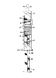
Fig. 1 is a side elevation view of the prefer-
red two-component medication syringe assembly of
the present invention;
Fig. 2 is a cross-sectional view of the syringe
assembly of Fig. 1 taken along line 2-2;
FigO 3 is a cross-sectional view of the syringe
assembly of Fig. 1 taken along line 3-3;
Fig. 4 is a cross-sectional view of the syringe
assembly of Fig. 1 taken along line 4-4;
Fig. 5 is a partially cross-sectioned view of
the syringe assembly, similar to Fig. 2, witll tip
-- 25 cap removed, schematically showing the mixing of
the two-medication components;
Fig. 6 is a cross-sectional view of the syringe
assembly of Fig. 5, similar to the cross-sectional
view of Fig. 3 but with the bypass stopper in the
bypass zone
Fig. 7 is a partially cross-sectioned view of
the preferred two-component medication syringe
assembly showing the position of the stopper and
the bypass stopper when the two-components o~ the
P-839
23~
medication are fully mixed;
Fig. ~ is a partially cross-sectioned view of
the preferred two-component medication syringe
assemblyt with hypodermic needle assembly attached,
schematically showing the vein indication test;
Fig. 9 is a partially cross-sectioned view of
the preferred two-component medication syringe
assembly, with hypodermic needle attached, sche-
matically showing the injection of the medication
and the function of the barrier flange in helping
to prevent medication rom being expelled through
the proximal end of the syringe barrel
Fig. lO is an en]arged perspective view of a
bypass stopper having a bypass stopper extension;
Fig. ll is an enlarged side elevation view of
the bypass stopper having a bypass stopper exten-
sion of Fig. lO;
Fig. 12 is a side elevation view of an alter-
native two-component medication syringe assembly,
with interior section partially exposed, sche-
matically showing the mixing of the two medication
components;
Fig. 13 is a side elevation view of an alterna-
tive plunger rod for use in the two-component
medication _syringe assembly of the present inven-
tion;
Fig. 14 is a partially cross-sectioned view of
the two-component medication syringe assembly of
the present invention illustrated with the alterna-
tive plunger rod of Fig. 13;
Fig. 15 is a cross-sectional view of the
two-component medication syringe assembly of Fig.
14 taken along line 15-l~;
Fig. 16 is a side elevation view of another
P-839
-12
alternative plunger rod, with gasket removed, for
use in the two-component medication syringe as-
sembly of the present invention;
Fig. 17 is a partially cross-sectioned view of
5 the two-component medication syringe assembly of
the present invention illustrated with the alterna-
tive plunger rod of Fig. 16 with a sealing gasket
attached,
Fig. 18 is a cross-sectional view of the
two-component medication syringe assembly of Fig.
17 taken along line 18-18;
Fig. 19 is a side elevation view of the sealing
gasket for use with the alternative plunger rod of
Fig. 16;
Fig. 20 is a cross-sectional view of the
sealing gasket of Fig. 19 taken along lines 20-20
Fig. 21 is a side elevation view of still
another alternative plunger rod for use in the
two-component medication syringe assembly of the
present invention;
Fig. 22 is a partially cross-sectioned view of
the two-component medication syringe assembly of
the present invention illustrated with the alterna-
tive plunger rod of Fig. 21;
Fig. 23 is a cross-sectional view of the
two-component medication syringe assembly of Fig.
22 taken along line 23-23;
Fig. 24 is a partially cross-sectioned side
elevation view of an alternative syringe barrel and
bypass stopper for use in the two-component medica-
tion syringe assembly of the present invention,
illustrating a radially inwardly projecting bypass
Fig. 25 is a cross-sectional view of th~
syringe barrel and bypass stopper of Fig. ~4 taken
P-~39
-13-
along line 25-25;
Fig. 26 is a partial side elevation view of an
alternative syringe barrel and shield o~ the
present two-component medication s~ringe assembly
5Fig. 27 is the two-component medication syringe
assembly of Fig. 26 illustrating the shield removed
and separated from the syringe barrel; and
Fig. 28 is a cross-sectional view of the
two-component medication syringe assembly of Fig.
1026 taken along line 28-2~.
_ETAI l,ED DESCRI P~I ON
While this invention is satisfied by embodi-
ments in many different forms, there is shown in
the drawings and will herein be described in detail
preferred embodiments of the invention with the
understanding that the present disclosure is to be
considered as exemplary of the principles of the
invention and is not intended to limit the inven-
tion to the embodiments illustrated. The scope of
the invention will be measured by the appended
claims and their equivalents.
Adverting to Figs. l through 7, a two-component
medication syringe 20 with vein indication test
capacity includes an elongate substantially cylin-
drical barrel 21 having an interior wall 23 de-
fining a chamber 22 for retaining fluid. A tapered
tip 24 extends from a distal end 25 of the barrel
and contains a passageway 26 therethrough communi-
cating with chamber 22. For purposes of the
description of the present invention, the term
"distal end~ is meant to refer to the end ~urthest
from the person holding the syringe, whereas the
term ~proximal end" is meant to refer to the end
P-a39
,
-14~ d ~ ~
closest to the holder of the syringe. Tapered tip
24 is adapted to accept a hypodermic needle (no~
shown). A closure means such as a preferably
resilient tip cap 29 is releasably connected to
tapered tip 24 and seals passageway 26 in an
air-tight manner Tip cap flange 30 is provided to
facilitate installation and removal of the tip
cap. A flange 27 is also provided at the proximal
end of the barrel to facilitate handling and
positioning the syringe.
A flexible bypass stopper 31 is slidably
positioned in fluid-tight arrangement inside the
barrel. The bypass stopper outside diameter is
larger than the inside diameter of the barrel so
that the bypass stopper, when introduced into the
syringe barrel, is compressed enough to provide
adequate pressure between the syringe barrel and
the stopper to seal this interEace, but yet remains
slidable within the barrel under the influence of
force.
Syringe barrel 21 also includes a bypass 34
represented by a raised peripheral portion of the
barrel extending radially outwardly and which
defines bypass zone z along the barrel. The
bypass, as best illustrated in Fig. 2, effectively
changes the inside diameter of the syringe barrel
as measured through the bypass zone. Also, the
bypass zone is longer along the longitudinal axis
of the barrel than the length of bypass stopper 31
along the longitudinal axis of the barrelO As will
be shown hereinafter, the bypass is large enough to
allow fluid flow around the bypass stopper when the
bypass stopper is positioned within the bypass zone.
P-839
3~d~
A flexible stopper 36 is slidably positioncd in
fluid-tight engagement inside the barrel. Stopper
36 is adapted to engage a rigid plunger rod 37
having an elongate body portion 38, In the pre-
ferred embodiment, the stopper contains internalthread 39 which can engage external thread 40 on
the plunger rod, The plunger rod is accessible
outside of the proximal end of the barrel and is
provided to move the stopper along the barrel to
for~e fluid into or out of the chamber through the
passageway. Disc-shaped plunger rod flange 42 is
provided as a convenient structure for applying
forces to move the plunger rod with respect to the
syringe barrel. Plunger rod flange 41 is provided
to supply a large surface area to transmit force
from the plunger rod to the stopper, in a direction
toward the stopper, without damaging the stopper,
A barrier flange 43 on elongate body portion 38
is positioned transversely with respect to a
longitudinal axis 46 of body portion 38 of the
\ plunger rod and intermediate the ends thereof,
Barrier flange 43 pro~ects outwardly from body
portion 38 into the space between the inside of the
barrel and the outside of the body portion wherein
the area described by periphery 47 of barrier
flange 43, as viewed along longitudinal axis 46 of
the plunger rod, as best illustrated in Fig, 4, is
desirably at least about 87 percent and preferably
at least about 90 percent as large as the area
described by interior wall 23 of the barrel when
viewed along the longitudinal axis of the barrel.
In this preferred embodiment there is a space 48
between the outside of the barrier flange and the
inside of the barrel. As will be explained in more
~3
P-839
327
detail hereinafter barrier flange 43 acts as
barrier ~or blocking the path of fluid which may be
propelled, or blown back, in a distal direction
through the bypass while the syringe is being
operated. The barrier flange is positioned on the
body portion of the plunger rod so that the barrier
flange is within chamber 22 when stopper 36 is
positioned in the bypass zone.
The plun~er rod can be installed when the
syringe is assembled, or it may be provided as a
separate unattached component which is engaged to
the stopper at the time of use. It will be appar-
ent to one skilled in the art that numerous con-
structions can be used to join a stopper and a
plunger rod and that the arrangement described
above is exemplary of these many possibilities.
Also, it is within the purview of this invention to
include a one-piece plunger rod-stopper assembly.
The preferred embodiment of the instant inven-
tion contains two components of a medication whichwill be mixed at the time of use. A liquid first
component of medication 44 is contained within the
proximal end of chamber 22 between bypass stopper
31 and stopper 36. Note that the bypass stopper is
positioned -outside of the bypass zone adjacent to
the proximal end of the bypass. A second component
of medication 45 is contained within the distal end
of chamber 22 between bypass stopper 31 and the
distal end of the barrel. The second component of
medication may be in the form of liquid, liquid
soluble powder or combinations thereof. The
preferred embodiment is described with the second
component being a lyophilized powder.
It should be noted that minimal force is
P-839
-17-
~23~7
required to move a flexible stopper along a barrel
when it is well lubricated or ~hen the liquid being
injected acts as a lubricant. However, when the
stopper remains in one position, even for a short
period of time, the pressure exerted between the
stopper and the syringe barrel tends to force
liquid or lubricant out from the interface between
the stopper and the barrel. As a result, the
amount of force required to start the stopper
moving along the syringe barrel increases drarnat-
ically. This increased force is called the break-
out force. For many syringes, the breakout force
is so high that if the user initially pulls on the
plunger rod, it will disengage from the stopper.
However, in the instant invention, stopper flange
41 allows the user to provide more force to the
stopper, in the direction toward the stopper, than
could be applied by the plunger rod in a direction
away from the stopper, to facilitate overcoming the
breakout force and moving the stopper. It can be
seen that the breakout force is increased where, as
with the instant invention, there are two stoppers
to be moved.
Mixing the first and second components of the
medication, as best illustrated in Figs. 5 tbrough
7, is accomplished by removing the tip cap and
orienting the syringe so that the tip faces in an
upwardly direction as more specifically illustrated
in Fig. 5. The user, while holding barrel 21 in
one hand, pushes plunger rod 37 firmly in a direc-
tion toward the distal end of the barrel. Once the
breakout force of the stopper is overcome, stopper
36 will move toward the distal end of the syringe
barrel, exerting pressure on first component 44,
P-g39
-18-
lZ6~3~'7
which in turn exerts pressure on bypass stopper
31. The stopper, first component of medication and
the bypass stopper ~ill continue to move along the
barrel until the bypass stopper is positioned
within the bypass zone. At this point, the pres-
sure exerted on the liquid first component of the
medication by stopper 36 will force the liquid
through bypass passageway 35 between the bypass and
the bypass stopper, around the bypass stopper, into
the area containing the second component of medica-
tion, as best illustrated in Fig. 5. Motion of the
bypass stopper toward the distal end of the syringe
barrel and liquid entering the distal end of the
syringe barrel, through the bypass, will displace
any air contained therein and force it out of the
barrel via passageway 26. Pressure on the plunger
rod is continued until stopper 36 is adjacent to
bypass stopper 31 and all of the liquid component
is substantially in distal chamber portion 21
between the distal end of the barrel and the bypass
stopper. It may now be necessary to agitate the
syringe barrel to complete the mixing process. At
this point, the two components of the medication
are mixed, and the medication is ready for injec-
tion.
Referring now to Figs. 8 and 9, injection ofthe medication into the vein of patient P requires
the placement of a sterile hypodermic needle
assembly 50 on the tapered tip of the syringe
barrel, and forcing sharp cannula 51 through the
patient's skin S into the vein V. To assure that
the cannula is properly inserted in the vein, the
plunger rod can be drawn away from the distal end
of the syringe moving the stopper 36 in that
P-~39
-19- ~LZ~232~
direction to create a reduced pressure zone inside
the chamber which will draw blood B from the vein
into the chamber. The presence of blood in the
chamber will be visual evidence that the cannula is
properly placed in a vein. The above described
procedure for determining whether or not the
cannula is properly placed in a vein is called the
vein indication test.
The vein indication test capacity of the
instant invention is made possible because the
volume of the components of the medication, when
mixed, is approximately equal to the volume defined
within distal chamber portion 32 between the bypass
stopper and the distal end of the barrel when the
bypass stopper is within the bypass zone. This
volumetric relationship allows the final precise
positioning of the bypass stopper by direct contact
with stopper 36 which is controlled by plunger rod
37. Most i~portantly, when withdrawing the plunger
rod to perform the vein indication test, it is only
necessary to move stopper 36 and not bypass stopper
31. Since only one stopper is being moved, the
force required to move the plunger rod is less, and
there is less chance that the plunger rod will
become disengaged from the stopper. Also, when
only one stopper is being moved, there is less
chance that non-sterile air will leak around
stopper 36 to the lower pressure area created
within the barrel in attempting to move the stopper
along the barrel in a direction toward the proximal
end.
The vein indication test should also be per-
formed when injection of medication into a vein or
artery is not desirable. For example, for
20 ~ 3~
injecting medication intramuscularly. In tllis
case, the sharpened cannula of the hypodermic
needle, connected to the syringe assembly, is made
to pierce the injection site on the patient and the
plunger rod is drawn away from the distal end of
the syringe, moving stopper 36 in that direction,
to create a reduced pressure zone inside the
chamber. The absence of blood in the chamber i5
visual evidence that the cannula is not improperly
placed in a vein or arteryO
When it is determined that the cannula is
properly positioned in the patient, the medication
may be injected, in the normal manner, by forcing
the plunger rod toward the distal end of the
barrel. The motion of plunger rod 7 forces stopper
36 along the barrel, which in turn forces any
liquid that may be between stopper 36 and bypass
stopper 31 through the bypass passageway into the
distal chamber portion. At this point stopper 36
is in contact with bypass stopper 31 and motion o~
`~ the plunger rod forces both stoppers along the
barrel, thus forcing the medication through pas-
sageway 26, cannula 51 and into the patient.
As stopper 36 passes through the bypass zone,
as best illustrated in Fig. 9, there is a ten~ency
for a small amount of medication trapped in bypass
passageway 35 and in the spaces between the stopper
ribs and the inside of cylindrical barrel 21 to be
projected or blown back in a rearward or proximal
3~ direction toward the operator's hands and/or
syringe plunger rod 37. Medication being projected
in a distal direction is indicated as M in Fig~ 9.
Barrier flange 43 positioned transversely with
respect to the longitudinal axis of body portion 38
P-839
-21- ~Z~23z7
is also positioned so that it is within the cha~bcr
when stopper 36 is in the bypass zone. The barriec
flange acts as a barrier to catch blown back
medication which is deposited on the plunger rod
and may tend to migrate along the plunger rod
toward the operator's hands, and also acts as a
barrier to blown back medication directed toward
the interior of the barrel and toward the openings
defined by the exterior of the plunger rod and the
interior of the barrel. AlSo, medication blown
back onto interior wall 23 of the barrel will be
driven by gravity toward the lower portions of that
wall tending to run along the syringe barrel from
the lowest point. Although there is a slight
clearance between barrier flange 43 and the inside
of cylindrical barrel 21 the plunger rod may also
tend to rest on the lower side of the barrel so
that barrier flange 43 may also tend to block flow
directly along the inside of the cylindrical
barrel. In this preferred embodiment, the barrier
flange, when viewed along longitudinal axis 46 of
the plunger rod, is at least about 90 percent as
large as the area described by interior wall 23 of
the barrel when viewed along the longitudinal axis
25- of the barrel.
Barrier flange 43 is an important element of
the instant invention in that it helps prevent
medication blown back from the bypass from being
deposited on the operator's hands or the plunger
rod near the operator's hands. The protection
provided by the barrier flange is important because
some medications contain ingredients that should
not come in contact with the operator's skin
Also, the presence of this liquid medication is at
P-~39
-22- ~2~3~7
least a nuisance and compromises the cleanliness of
the injection process.
Referring now to Figs. 10, 11 and 12, an
alternative two-component medication syringe
assembly 54 of the instant invention includes
components which are substantially identical to the
components of the embodiment of FiyS. 1-9. Accord-
ingly, similar components performing similar
functions will be numbered identically to those
components in the embodiment of Figs. 1-9, except
that the suffix ~a" will be used to identify the
- components of Figs. 1~-12. This alternative
two-component medication syringe assembly includes
an elongate substantially cylindrical barrel 21a
having an interior wall 23a defining a chamber ~2a
for retaining fluid. A tapered tip 24a extends
from distal end 25a of the barrel. Barrel 21a also
includes a bypass 34a represented by a raised
peripheral portion of the barrel extending radially
outwardly, defining a bypass zone along the bar-
rel. This embodiment includes a bypass stopper
31a, a stopper 36a and a plunger rod 37a. Plunger
rod 37a includes an elongate body portion 38a
having a threaded distal end portion (not shown)
for engaging a complementary threaded portion (not
shown) in stopper 36a. A plunger rod barrier
flange 43a is positioned transversely with respect
to longitudinal axis 46a of body portion 3~a and
intermediate the ends thereof. The barrier flange
projec~s outwardly from body portion 38a into tile
space between the inside of the barrel and the
outside of the body portion wherein the area
described by the periphery of the barrier flange,
as viewed along the longitudinal axis 46a o the
P-839
-23- ~ Z ~
plunger rod, is desirably at least 87 percent and
preferably at least about 90 percent as large as
the area described by ~he interior wall 23a of the
barrel when viewed along the longitudinal a~is of
s the barrel. Barrier flange 43a is positioned on
the body portion of the plunger rod so that th~
barrier flange is within chamber 22a when stopper
36a is positioned in the bypass zone.
This alternative embodiment also includes a
bypass stopper extension 55. The bypass stopper
extension includes a distal extension rib 56
contacting interior wall 23a of the barrel and a
recess 57 between extension rib 56 and bypass
stopper 31a~ This recess is capable of being in
fluid communication with the bypass, as best
illustrated in Fig. 12. The extension rib includes
one or more grooves 58 for allowing fluid communi-
cation between the recess 57 and chamber 22a.
Grooves 58 are positioned angularly with respect to
the longitudinal axis 59 of the bypass stopper
extension so that fluid passing through the grooves
is directed angularly with respect to the longi-
tudinal axis of the barrel, as best illustrated in
Fig. 12. Grooves 58 are prefe~ably positioned
angularly with respect to longitudinal axis 59 at
angle A. While not limiting the present invention
thereto, angle A is preferably within the range of
about 30 to 80, with 60~ being the most desirable
angle. It is within the purview of this invention
to include a bypass stopper extension wherein the
individual ~rooves are at different angles with
respect to the longitudinal axis. The angular
orientation of the grooves causes liquid passing
therethrough to be directed angularly with respect
P-839
-24- ~2~
to the longitudinal axis of the barrel toward the
interior wall of the barrel where the liquid tends
to flow around the interior surface of the chamber
causing a swirling action therein. ThiS s~lirling
action, facilitates the mixing of the two
components of the medication. Also, the angularly
positioned grooves preferably direct the liquid
from the bypass away from passageway 26a of the
syringe barrel to minimize the possibility of
liquid being expelled through the passageway dl~ring
the mixing process and before all gases are expel-
led from the chamber. It is also within the
purview of the present invention to include a
bypass stopper and a bypass stopper extension which
are of a unitary one-piece construction.
In order to have vein indication test capacity
with the present alternative embodiment the barrel
must be proportioned so that when bypass stopper
31a is positioned in the bypass zone with recess 57
in fluid communication with the bypass and distal
extension rib 56 positioned outside of the bypass
zone, as best illustrated in Fig. 12, the volume
defined within the chamber between distal end 67 of
bypass stopper extension 55 and the distal end of
the barrel is approximately- the volume of the
combined components of the medication.
Referring now to Figs. 13; 14 and 15, an
alternative two-component medication syringe
assembly 70 o~ the instant invention includes an
elongate substantially cylindrical barrel 71 having
an inside ~all 82 defining a chamber 72 and a
bypass 78 represented by a raised peripheral
portion of the barrel extending radially out~ardly
defining a bypass zone along the barrel. ThiS
P-839
-25~
embodiment also includes a bypass stopper 73, a
stopper 74 and a plunger rod 75. Plunger rod
includes an elongate body portion 76 having a
threaded distal end portion 77 for engaging a
complementary threaded portion ~not shown) in
stopper 74. A plunger rod barrier flange 79 i~
positioned transversely with respect to longitu-
dinal axis 88 of the body portion and intermediate
the ends thereof. The barrier flange projects
outwardly from body portion 76 into the space
between the inside of the barrel and the outside of
the body portion. A resilient lip portion 80 o
barrier flange 79 projects radially outwardly
ending in periphery 81. The outside diameter
described by the lip portion of the barrier ~lange
is greater than the inside diameter of the barrel
before the plunger rod is assembled into the
barrel. Accordingly, upon assembly, the lip
portion is partially deflected by the inside wall
of the barrel causing a slidable engagement between
the lip portion and the inside ~all of the barrel.
Accordingly, barrier flange 79 acts as a barrier
for blocking the path of fluid which may be pro-
pelled in a distal direction through the bypass
while the syringe assembly is being operated.
Adverting to Figs. 16 through 20, ano~her
alternative two-component medication syringe
assembly 100 includes an elongate barrel 101 having
an interior wall 113 defining a chamber 102 for
retaining medication and a raised elongate periph-
eral portion in the barrel serving as a bypass
103. A bypass stopper 104 is slidably positioned
in fluid-tight engagement inside the barrel and a
stopper 105 is also slidably positioned in
P-~39
fluid-tight engagement inside the barrel. A rigid
plunger rod 107 includes an elongate body portion
108 defining a longitudinal axis 109 and a threaded
distal end portion 110 for engaging stopper 105.
~ody portion 108 includes a barrier flange 111
which is positioned transversely with respect to a
longitudinal axis 109 of the body portion and
intermediate the ends thereof. The barrier flange
projects radially outwardly from the body portion
into the space between the inside of the barrel and
the outside of the body portion. A resilient
elastomeric gasket 112 is part of the bareier
flange, and is positioned along the periphery of
barrier flange base portion 106 in an annular
recess 114 of the base portion. In this embodiment
gasket 112 has a substantially circular cross
section and is similar to the known o~ring. When
gasket 112 is positioned on base portion 106 in
annular recess 114t the outside diameter described
by the gasket, and therefore the barrier flange, is
greater than the inside diameter of the barrel.
When the plunger rod is inserted into the chamber
the gasket is partially compressed by the inside
wall of the barrel causing a slidable engagement
between the gasket and the interior wall of the
barrel so that the barrier flange acts as a barrier
for blocking the path of Eluid which may be propel-
led in a distal direction through the bypass while
the syringe is being operated. It should be noted
that the barrier Elange is positioned along elon-
gate body portion 108 of the plunger rod so that it
is within the chamber when stopper 105 is posi-
tioned in bypass zone Z. It should also be noted
that the outside diameter of the base of the
P-839
-27~ 3~
ann~lar recess 114 in base portion 106 is larger
than the inside diameter of the resilient elasto-
meric gasket so that the gasket is stretched, and
in tension, when positioned in the annular recess
5 or the base portion. This tension will cause the
gasket to remain in its position with respect to
base portion 106 and not be easily removed there-
from. It will be apparent to one skilled in the
art that there are numerous structures and methods
10 for obtaining a resilient portion along the periph-
ery of a rigid body, including adhesive mounting of
the resilient material, shaping the periphery o
the barrier flange so that it is structurally
resilient, two-shot injection molding wherein one
15 component is a resilient material, and the other is
a rigid material, and that the above structure,
using a circularly shaped gasket in an annular
recess, is exemplary of these many possibilities.
Referring now to Figs. 21, 22 and 23, another
20 alternative two-component medication syringe
assembly 120 includes an elongate barrel 121 having
a chamber 122 for retaining medication and a raised
elongate peripheral portion serving as a bypass 123
defining a bypass zone Z. A bypass stopper 124 and
25 a stopper 125 are slidably positi~ned in fluid-
tight engagement inside the barrel. A ~igid
plunger rod 127 includes an elongate body portion
128 defining a longitudinal axis 129 and a threaded
distal end portion 130 for engaging stopper 125. A
30 barrier flange 131 is positioned transversely with
respect to longitudinal axis 129 of the body
portion and intermediate the ends thereof. The
barrier flange projects outwardly from bod~ portion
128 into the space between the inside of the barrel
~L2~Z3~7
-28-
and the outside of the body portion. The plunger
rod also includes a second barrier flange 133
positioned transversely with respect to longitu-
dinal axis 129 and between barrier flange 13~ and
the proximal end of body portion 128 so that the
second barrier flange is also within the chamber
when stopper 125 is positioned in the bypass zone,
The area described by the periphery of the barrier
flange and the second barrier flange as viewed
along longitudinal axis 129 is desirably at least
about 87 percent and preferably at least about 90
percent as large as the area described by the
interior wall of the barrel when viewed along the
longitudinal axis of the barrel. The barrier
flange and the second barrier flange act as
barriers for blocking the path of fluid which may
be propelled in a distal direction through the
bypass while the syringe is being operated, The
second barrier flange, in this embodiment, provides
extra protection by potentially being able to be in
the path of blown back medication which is missed
by the first barrier flange. Also, a second
barrier flange can be used to assist in maintaining
the concentricity between the plunger rod and the
barrel so that the first barrier flange may have a
very fragile sealing means or gasket or resilient
lip, while the second barrier flange prevents the
sealing means from experiencing excessive
stresses. It is within the purview of the present
invention to include multiple barrier flanges
wherein one or more of the flanges include the
various features of the present invention such as a
sealing means, a gasket, and a resilient lip por-
tion for causing a slidable engagement between the
barrier flange and the inside wall of the barrel.
P-~39
-29- ~26~32~
~ eferring now to Figs, 24 and 25, an alternate
syringe barrel 63 for use with the two-component
medication syringe assembly of the instant ~nven-
tion includes a barrel portion 60 having a chamber
61 for retaining fluid and a bypass 62 repeesented
by a raised peripheral portion of the barrel
extending radially inwardly defining a bypass ~one
along the barrel, The bypass zone is longer along
the longitudinal axis of the barrel than the length
of bypass stopper 64. The bypass is large enough
to deflect the bypass stopper so that when the
bypass stopper is in the bypass zone, liquid can
flow around the bypass stopper through bypass
passageways 65, Although the bypass in the various
embodiments described hereinabove is substantially
aligned with the longitudinal axis of the syringe
barrel it is within the purview of the present
invention to include syringe barrels having bypas-
ses which are oriented at an angle with respect to
the syringe barrel longitudinal axis and bypasses
which are curved or curvilinearly shaped so that
the distal end of the bypass is not parallel with
the longitudinal axis of the syringe barrel.
AdVerting to Figs. 26, 27 and 28, another
alternative syringe barrel 92 for use with the
instant two-component medication syringe assembly
includes barrel portion 93 having a chamber 94 for
retaining fluid and a bypass (not shown), A
tapered tip 83 extends from the distal end of the
barrel and contains a passageway 84 therethrough
communicating with chamber 94 a needle 85 with a
sharp distal end 86 and a lumen 87 is fixedly held
in passageway 84, via epoxy, adhesive or other
suitable means, so that the lumen is in fluid
P-839
-30~ 3~7
communication with chamber 94. Flexible necdlc
shield 89 has an open end 90, a closed end 91 and a
receptacle therein. The needle shield is removably
attached to tapered tip 83. shield 8~ is si~ed so
that, when it is attached to the tapered tip, sharp
distal end 86 is embedded in closed end 91 of the
needle shield so that lumen 87, and therefore
passageway 8~, are sealed in an air-tight arrange-
ment. Removal of the shield exposes needle 85 and
allows flow of fluid from chamber 94 through
passageway 84 and lumen 87. The above described
structure eliminates the need for separate hypo-
dermic needle assembly.
The syringe barrel may be constructed of
thermoplastic material such as polypropylene or of
glass. The latter material is preferred due to its
transparency, low moisture vapor transmission eate
and compatability with many medication formula-
tions. A wide variety of materials are suitable
for the stopper, bypass stopper, resilient gasket
and tip cap with natural rubber and butyl rubber
being preferred. The choice of stopper and tip cap
material formulations will be highly dependent on
compatability with the medication to be stored. A
wide vaEiety of rigid materials are suitable for
the plunger rod with thermoplastic materials such
as polypropylene, polyethylene and polystyrene
being preferred. It is preferred that all medica-
tion contacting elements of the two-component
medication syringe assembly be sterile when used.
Accordingly, materials should be selected for
compatability with the sterilization process being
used.
P-~39
-31-
Thus it can be seen that the present invention
provides a simple straight-forward, reliable,
easily fabricated syringe assembly for storage,
mixing and administering of two-component medica-
tions. The instant invention minimizes contamin-
ation potential by allowing the mixing and adminis-
tering steps to be performed without puncturing
stoppers or transferring the medication components
through surfaces which are exterior to the syringe
assembly. The instant invention is capable of
easily performing the vein indication test and it
includes structure for blocking or preventing
medication from being discharged through the
proximal end of the syringe barrel during the
injection process.