Sélection de la langue

Search

Sommaire du brevet 1262709 

Énoncé de désistement de responsabilité concernant l'information provenant de tiers

Une partie des informations de ce site Web a été fournie par des sources externes. Le gouvernement du Canada n'assume aucune responsabilité concernant la précision, l'actualité ou la fiabilité des informations fournies par les sources externes. Les utilisateurs qui désirent employer cette information devraient consulter directement la source des informations. Le contenu fourni par les sources externes n'est pas assujetti aux exigences sur les langues officielles, la protection des renseignements personnels et l'accessibilité.

Disponibilité de l'Abrégé et des Revendications

L'apparition de différences dans le texte et l'image des Revendications et de l'Abrégé dépend du moment auquel le document est publié. Les textes des Revendications et de l'Abrégé sont affichés :

  • lorsque la demande peut être examinée par le public;
  • lorsque le brevet est émis (délivrance).
(12) Brevet: (11) CA 1262709
(21) Numéro de la demande: 1262709
(54) Titre français: APPAREIL-DOSEUR DE MATIERES PATEUSES, NOTAMMENT DE LA CHAIR A SAUCISSE
(54) Titre anglais: APPARATUS FOR THE PORTIONWISE DELIVERY OF PASTY MATERIALS, PARTICULARLY SAUSAGE STUFFING
Statut: Périmé et au-delà du délai pour l’annulation
Données bibliographiques
(51) Classification internationale des brevets (CIB):
  • A22C 11/08 (2006.01)
  • A22C 11/02 (2006.01)
(72) Inventeurs :
  • HEGELMANN, HEINZ-DIETER (Allemagne)
  • KUNIG, HELMUT (Allemagne)
  • METTE, MANFRED (Allemagne)
(73) Titulaires :
  • NORDISCHER MASCHINENBAU RUD. BAADER GMBH + CO KG
(71) Demandeurs :
  • NORDISCHER MASCHINENBAU RUD. BAADER GMBH + CO KG (Allemagne)
(74) Agent: ROBIC, ROBIC & ASSOCIES/ASSOCIATES
(74) Co-agent:
(45) Délivré: 1989-11-07
(22) Date de dépôt: 1986-01-06
Licence disponible: S.O.
Cédé au domaine public: S.O.
(25) Langue des documents déposés: Anglais

Traité de coopération en matière de brevets (PCT): Non

(30) Données de priorité de la demande:
Numéro de la demande Pays / territoire Date
P 35 00 697.8 (Allemagne) 1985-01-11

Abrégés

Abrégé anglais


ABSTRACT OF THE DISCLOSURE:
Appartus for delivering pasty substances in
portions with respect to at least one of predetermined
weight and volume, comprising a machine frame having inter
alia a side and a front, conveyor means including a rotor
driven to rotate about an axis of rotation in a casing for
the rotor and having displacement chambers on its
circumference, and further including an inlet port and
outlet port, storage hopper means for receiving a supply of
the substance, which storage hopper means are under
atmospheric pressure, define at least a flank and a base,
are provided with an outlet in the region of the base and
include driven plugging means, and pivotable mounting means
for mounting the storage hopper means pivotably relative to
the machine frame. The conveyor means are associated to the
flank of the storage hopper means remote from the front of
the machine frame in such a way that the axis of rotation of
the rotor is arranged substantially perpendicular to the
flank, the latter being equipped with a cover flange forming
part of the mounting means and a closure for the rotor
casing of the conveyor means. The outlet port of the
conveyor means is positioned at a higher level with respect
to the inlet port, the latter coinciding with the outlet of
the hopper means in the working position of the latter.

Revendications

Note : Les revendications sont présentées dans la langue officielle dans laquelle elles ont été soumises.


The embodiments of the invention in which an
exclusive property or privilege is claimed are defined as
follows:
1. Apparatus for delivering pasty substances in
portions with respect to at least one of predetermined
weight and volume, the apparatus comprising
(a) a machine frame having inter alia a side and a
front,
(b) conveyor means including a rotor driven to rotate
about an axis of rotation in a casing for said
rotor and having displacement chambers on its
circumference, and further including an inlet port
and outlet port,
(c) storage hopper means for receiving a supply of
said substance, which storage hopper means are
under atmospheric pressure, define at least a
flank and a base, are provided with an outlet in
the region of said base and include driven
plugging means, and
(d) pivotable mounting means for mounting said storage
hopper means pivotably relative to said machine
frame, the apparatus being arranged such that,
(e) said conveyor means are associated to said flank
of said storage hopper means remote from said
front of said machine frame in such a way that
said axis of rotation of said rotor is arranged
substantially perpendicular to said flank, the
latter being equipped with a cover flange forming
part of said mounting means and a closure for said
rotor casing of said conveyor means, and
(f) said outlet port of said conveyor means is
positioned at a higher level with respect to said
inlet port, the latter coinciding with said outlet

of said hopper means in the working position of
the latter.
2. Apparatus as claimed in claim 1, wherein said
outlet port of said conveyor means is arranged in a rotation
plane defined by said rotor.
3. Apparatus as claimed in claim 1, wherein said
storage hopper is mounted so as to pivot about a pivot axis
substantially parallel to a central axis of said hopper.
4. Apparatus as claimed in claim 2, wherein said
storage hopper is mounted so as to pivot about a pivot axis
substantially parallel to a central axis of said hopper.
5. Apparatus as claimed in claim 1, wherein said
storage hopper is mounted so as to pivot about a pivot axis
substantially perpendicular to a central axis of said
hopper.
6. Apparatus as claimed in claim 2, wherein said
storage hopper is mounted so as to pivot about a pivot axis
substantially perpendicular to a central axis of said
hopper.
7. Apparatus as claimed in claim 3, wherein said
pivot axis is provided on the side of said storage hopper
facing said outlet port of said conveyor means.
8. Apparatus as claimed in claim 4, wherein said
pivot axis is provided on the side of said storage hopper
facing said outlet port of said conveyor means.
9. Apparatus as claimed in claim 5, wherein said

pivot axis is provided on the side of said storage hopper
facing said outlet port of said conveyor means.
10. Apparatus as claimed in claim 6, wherein said
pivot axis is provided on the side of said storage hopper
facing said outlet port of said conveyor means.

Description

Note : Les descriptions sont présentées dans la langue officielle dans laquelle elles ont été soumises.

~2~i27~
The present invention relaLes to an apparatus for
delivering pasty substances (materials), particularly
sausage stuffing, in portions of predetermined weight and/or
volume.
A similar apparatus is known and used in practice.
In this apparatus, use is made of a twin-screw conveyor,
whose inlet end is positioned below the storage hopper and
rises towards its outlet end. The conveyor screws can be
taken out towards the outlet particularly for the purpose of
cleaning the machine, and the upper part of the storage
hopper is tiltable. This known device has certain
disadvantages with regard to ergonomics due to the
arrangement or alignment of the conveyor relative to the
hopper, whereas the parts to be cleaned are difficult to~
reach and inspect, so that a regular cleaning and
maintenance causes various difficulties.
It is an essential object of the invention to
suggest an apparatus for the portioning of pasty substances,
which is improved under ergonomical aspects. Anothex
important object of the present invention is to improve the
structure and arrangement of such apparatus to enable an
easy handling for cleaning and maintenance purposes.
According to the present invention there is
pr~vided an apparatus for delivering pasty substances, in
portions with respect to at least one of predetermined
weight and volume, the apparatus comprising:
(a) a machine frame having inter alia a side and a
front,
(b) conveyor means including a rotor driven to rotate
about an axis of rotation in a casing for said
rotor and having displacement chambers on its
circumference, and further including an inlet port
and outle-t port,
(c) storage hopper means for receiving a supply of

7~39
-- 2
said substance, which storage hopper means are
under atmospheric pressure, define at least a
flank and a base, are provided wi-th an outlet in
the region of said base and include driven
plugging means, and
(d) pivotable mounting means for mounting said storage
hopper means pivotably relative to said machine
frame, the apparatus being arranged such that
(e) said conveyor means are associated to said flank
of said storage hopper means remote from said
front of said machine frame in such a way that
said axis of rotation of said rotor is arranged
substantially perpendicular to said flank, the
latter being equipped with a cover flange forming
part of said mounting means and a closure for said
rotor casing of said conveyor means, and
(f) said outlet port of said conveyor means is
positioned at a higher level with respect to said
inlet port, the latter coinciding with said outlet
of said hopper means in the working position of
the latter.
The advantages to be obtained thereby consist in
particular in the following:
- a low filling height in the case of a conventional
outlet height,
- easy dismantability and accessibility - all parts
in contact with the filling materia] can be
accessed, dismantled, and inspected easily, which
gives an optimum possibility of cleaning and
maintenance.
According to a preferred embodiment the outlet
port of the conveyor mav be located in -the rotation plane of
the rotor. Due to the thus resulting short guidance, of the
material being conveyed, which guidance is oE low flow
k~
~ .

~6~
- 3 -
resistance, this construction adds to the careful handling
of the material and prevents any risk of separation.
Under the aspect of an easy maintenance, it
is advantageous if the storage hopper is mounted pivo-tably
selec-tively about a pivot axis extending substantially
parallel or substantially perpendicular to its central
axis. It is particularly advantageous if the pivot axis is
1::

.2~
~ 4 --
the side of the storage hopper facing the outlet port of the
conveyor, because as a result the machine can still be
operated when its back and rear faces are inaccessible,
without thereby impairing the control and/or maintenance.
05
BRIEF DESCRIPTION OF THE DRAWINGS
Other and further objects of the present invention will
be apparent from the following description and claims and
are illustrated in the accompa.nying drawings, which by way
of illustration schematically show preferred embodiments of
the present invention and the principles thereof and what
now are considered to be the best modes contemplated for
applying these principles. Other emboaiments of the inven-
tion embodying the same or e~uivalent principles may be used
and structural changes may be made as desired by those
skilled in the art without departing from the present inven-
tion and the scope of the appended claims. In the drawings
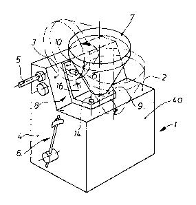
Fig~ l shows an overall view of an apparatus according
to the present invention in a centrally axono-
metric representation,
Fig. 2 shows the arrangement of the various individual
units by viewing into the apparatus frame; and

Fig. 3 shows a plan view for the arrangement of the
machine in operation.
DETAILED DESCRIPTION OF THE PREFERRED EMBODIMENT
05 A machine frame 1 is designed in desk- or lectern-like
manner and has a side face 4 and a front face 4a. The frame
is provided with a substantially planar table surface 2,
whose rearward edge is followed by an upwardly sloping desk
surface 3. Behind the desk surface 3 and from the side face
10---4 of machine frame 1 there projects a filling tube 5, con-
nection facilities for conventional, not shown accessories~
being provided in the region of said tube. A control lever
6 for the control of the apparatus, which can be operated by
the operator's knee or thigh is also located on the side
face 4. The table surface 2 serves to receive a storage
hopper 7, which is fixed to a mounting device in the form of
an angle bracket 8. This bracket 8 has a portion located on
the table surface 2, which portion is constructed as a flat
support plate 9, whereas a second bracket portion associated
to the desk surface 3 is constructed as a cover flange lO.
The arrangement and design of the storage hopper 7 is such
that the rear flank 11 thereof is supported against the
cover flange 10 and is connected two-dimensionally thereto.
Adjacent to its base the hopper 7 is provided with an outlet
13 passing through cover flange 10. The storage hopper 7

~ ~27~
-- 6 --
together with the angle bracket 8 is pivotably moun-ted about
a pivot a~is 14 which extends perpendicular to the table
surface 2. Thereb~ the hopper can be pivoted into a forward
open position as indicated by the right hand dash-dotted
05 lines in Fig~ 1. Selectively there may also be provided a
pivot axis 15 located in the region of the cover flange 10
and extending perpendi.cular to the central axis of the
storage hopper 7, which second axis serves for pivoting the
hopper into an open position indicated by the leEt-hand
10 dash-dotted lines. In the working position, the angle
bracket 8 is held pressed against the desk surface 3 by
means of appropriate fast action connection elements 1~ not
shown in detail. The cover flange 10 brings about the
sealing of a conveyor 17 which is arranged in a conveyor
15 housing formed by the rear part of the desk-like frame and
not referred to in detail in the drawings. This conveyor is
provided with not shown radial feed chambers and has an
outlet port 18 which is associated to the filling tube 5.
Thus, the conveyor 17 is inserted in the desk surface 3.
20 The outlet 13 at the bottom of the storage hopper 7 coinci-
des with an inlet port 19 oE the conveyor 17. A plugging
device 20 is located in the storage hopper 7 and can be
driven by a gear 21 inserted in the table surface 2.
For maintenance purposes and for cleaning the appara-
25 tus, the plugging device 20 is first removed from the

storage hopper 7. Thîs removal can be facilitated by using
a suitable fast action coupling. The fast action connection
elements 16 attaching the cover flange 10 to the desk sur-
face 3 are then released, whereupon the angle bracket 8 and
05 thus the hopper 7 are swung out. Not shown electrical
locking means in the region of the pivot axis 14 or 15 can
ensure that the apparatus cannot be swi-tched on when the
storage hopper 7 is swung out. In this position, the con-
veyor 17 is freely accessible in a handy working height, as
10 is the storage hopper 7 itself with all its connection faces
and openings, so that any cleaning and/or maintenance can be
performed correctly in an uncomplicated manner.
This work can even be performed in an unimpeded manner
if, as shown in Fig. 3, the back of the apparatus is placed
15 against a wall 25 and a work table 24 is arranged below the
filling tube 5.

Dessin représentatif
Une figure unique qui représente un dessin illustrant l'invention.
États administratifs

2024-08-01 : Dans le cadre de la transition vers les Brevets de nouvelle génération (BNG), la base de données sur les brevets canadiens (BDBC) contient désormais un Historique d'événement plus détaillé, qui reproduit le Journal des événements de notre nouvelle solution interne.

Veuillez noter que les événements débutant par « Inactive : » se réfèrent à des événements qui ne sont plus utilisés dans notre nouvelle solution interne.

Pour une meilleure compréhension de l'état de la demande ou brevet qui figure sur cette page, la rubrique Mise en garde , et les descriptions de Brevet , Historique d'événement , Taxes périodiques et Historique des paiements devraient être consultées.

Historique d'événement

Description Date
Inactive : CIB de MCD 2006-03-11
Inactive : Demande ad hoc documentée 1993-11-07
Le délai pour l'annulation est expiré 1993-05-08
Lettre envoyée 1992-11-09
Accordé par délivrance 1989-11-07

Historique d'abandonnement

Il n'y a pas d'historique d'abandonnement

Titulaires au dossier

Les titulaires actuels et antérieures au dossier sont affichés en ordre alphabétique.

Titulaires actuels au dossier
NORDISCHER MASCHINENBAU RUD. BAADER GMBH + CO KG
Titulaires antérieures au dossier
HEINZ-DIETER HEGELMANN
HELMUT KUNIG
MANFRED METTE
Les propriétaires antérieurs qui ne figurent pas dans la liste des « Propriétaires au dossier » apparaîtront dans d'autres documents au dossier.
Documents

Pour visionner les fichiers sélectionnés, entrer le code reCAPTCHA :


Pour visualiser une image, cliquer sur un lien dans la colonne description du document. Pour télécharger l'image (les images), cliquer l'une ou plusieurs cases à cocher dans la première colonne et ensuite cliquer sur le bouton "Télécharger sélection en format PDF (archive Zip)" ou le bouton "Télécharger sélection (en un fichier PDF fusionné)".

Liste des documents de brevet publiés et non publiés sur la BDBC .

Si vous avez des difficultés à accéder au contenu, veuillez communiquer avec le Centre de services à la clientèle au 1-866-997-1936, ou envoyer un courriel au Centre de service à la clientèle de l'OPIC.


Description du
Document 
Date
(aaaa-mm-jj) 
Nombre de pages   Taille de l'image (Ko) 
Revendications 1993-09-13 3 70
Dessins 1993-09-13 1 35
Abrégé 1993-09-13 1 31
Description 1993-09-13 7 203
Dessin représentatif 2002-03-07 1 11
Taxes 1991-10-14 1 31