Sélection de la langue

Search

Sommaire du brevet 1262751 

Énoncé de désistement de responsabilité concernant l'information provenant de tiers

Une partie des informations de ce site Web a été fournie par des sources externes. Le gouvernement du Canada n'assume aucune responsabilité concernant la précision, l'actualité ou la fiabilité des informations fournies par les sources externes. Les utilisateurs qui désirent employer cette information devraient consulter directement la source des informations. Le contenu fourni par les sources externes n'est pas assujetti aux exigences sur les langues officielles, la protection des renseignements personnels et l'accessibilité.

Disponibilité de l'Abrégé et des Revendications

L'apparition de différences dans le texte et l'image des Revendications et de l'Abrégé dépend du moment auquel le document est publié. Les textes des Revendications et de l'Abrégé sont affichés :

  • lorsque la demande peut être examinée par le public;
  • lorsque le brevet est émis (délivrance).
(12) Brevet: (11) CA 1262751
(21) Numéro de la demande: 1262751
(54) Titre français: BUSE AVEC ASSISTANCE D'AIR, AVEC DISPOSITIF POSITIONNEUR DE DEFLECTEUR
(54) Titre anglais: AIR ASSISTED NOZZLE WITH DEFLECTOR DIRECTING MEANS
Statut: Périmé et au-delà du délai pour l’annulation
Données bibliographiques
(51) Classification internationale des brevets (CIB):
  • B05B 1/04 (2006.01)
  • B05B 1/26 (2006.01)
  • B05B 7/04 (2006.01)
(72) Inventeurs :
  • HARUCH, JAMES (Etats-Unis d'Amérique)
(73) Titulaires :
  • SPRAYING SYSTEMS CO.
(71) Demandeurs :
  • SPRAYING SYSTEMS CO. (Etats-Unis d'Amérique)
(74) Agent: MARKS & CLERK
(74) Co-agent:
(45) Délivré: 1989-11-07
(22) Date de dépôt: 1985-04-12
Licence disponible: S.O.
Cédé au domaine public: S.O.
(25) Langue des documents déposés: Anglais

Traité de coopération en matière de brevets (PCT): Non

(30) Données de priorité de la demande:
Numéro de la demande Pays / territoire Date
602,227 (Etats-Unis d'Amérique) 1984-04-19

Abrégés

Abrégé anglais


ABSTRACT OF THE DISCLOSURE
An air assisted spray nozzle having a nozzle
body formed with an elongated mixing and atomizing
chamber having an air inlet orifice communicating
with one end of the chamber, a liquid inlet orifice
communicating with a side of the chamber, and a
nozzle tip having a discharge orifice located at the
end of the chamber opposite the air inlet orifice.
Transversely directed streams of pressurized air and
liquid enter and converge in the mixing and
atomization chamber of the nozzle body causing
preliminary atomization of the liquid, which is
thereupon directed under the force of the high
velocity air stream out the discharge orifice and
against a deflector flange of the nozzle tip which
further atomizes the liquid and directs it into A
well-defined flat fan spray pattern with uniform
distribution and liquid particle size. To enhance
preliminary atomization, the mixing and atomizing
chamber has an inwardly extending liquid impingement
post in diametrically opposed relation to the liquid
inlet orifice, and to facilitate further atomization
and controlled direction of the discharging spray the
deflector flange defines an arcuate shaped guide
surface which is substantially wider than the width
of the discharge orifice and has a terminal lip
transversely offset from the discharge orifice.

Revendications

Note : Les revendications sont présentées dans la langue officielle dans laquelle elles ont été soumises.


AN EMBODIMENT OF THE INVENTION TO WHICH AN EXCLUSIVE PROPERTY
OR PRIVILEGE IS CLAIMED ARE DEFINED AS FOLLOWS:
1. An air assisted spray nozzle comprising:
a hollow nozzle body,
means defining an air inlet orifice through
which a pressurized air stream is directed into said
body,
means defining a liquid inlet orifice through
which a liquid stream is directed into said body at
an angle to the direction of said pressurized air
stream,
said body having a mixing and atomizing chamber
within which said liquid and air stream converge to
cause preliminary atomization of said liquid,
means defining a discharge orifice in fluid
communication with said mixing and atomization
chamber and through which said atomized liquid is
directed, and
means defining a deflector flange disposed
downstream of said discharge orifice and transverse
to the direction of travel of said atomized liquid
through said discharge orifice against which said
atomized liquid impinges to causes further atomization
of the liquid and the transverse direction of the
further atomized liquid into a well-defined, flat fan
spray pattern.
2. The air assisted spray nozzle of claim 1 in
which said discharge orifice is in substantial
longitudinal alignment with said air inlet orifice.
3. The air assisted spray nozzle of claim 2 in
which said liquid inlet orifice is disposed at an
angle of about 90° to said air inlet orifice.
4. The air assisted spray nozzle of claim 3 in
which said nozzle body has an impingement post
extending into said mixing and atomizing chamber,
said post being in substantial alignment with said
-7-

liquid inlet orifice and having an end face against
which a liquid stream directed into said chamber from
said liquid stream directed into said chamber from
5. The air assisted spray nozzle of claim 4 in
which said post is disposed transversely to the
direction of travel of a pressurized air stream
directed into said chamber from said air inlet
orifice.
6. The air assisted spray nozzle of claim 5 in
which said mixing and atomizing chamber has an
elongated configuration disposed in axial alignment
with said air inlet orifice and said discharge
orifice.
7. The air assisted spray nozzle of claim 6 in
which said post end face is disposed on the
longitudinal axis of said mixing and atomizing
chamber.
8. The air assisted spray nozzle of claim 1 in
which said discharge orifice defining means is a
nozzle tip removably mounted on said nozzle body.
9. The air assisted spray nozzle of claim 8 in
which deflector flange is an integrally formed part
of said nozzle tip.
10. The air assisted spray nozzle of claim 9 in
which said deflector flange defines an arcuate shaped
deflector surface that changes direction of travel of
the atomized liquid directed through said discharge
orifice.
11. The air assisted spray nozzle of claim 10
in which said arcuate deflector surface extends from
the outlet of said discharge orifice to a terminal
lip transversely offset from said discharge orifice,
12. The air assisted spray nozzle of claim 10
in which said deflector flange has a width greater
-8-

than the width of the outlet of said discharge
orifice.
13. an air assisted spray nozzle comprising:
a hollow nozzle body,
means defining an air inlet orifice through
which a pressurized air stream is directed into said
body,
means defining a liquid inlet orifice through
which a liquid stream is directed into said body at
an angle to the direction of said pressurized air
stream,
said body having a mixing and atomizing chamber
within which said liquid and air streams converge to
cause preliminary atomization of said liquid into
liquid particles,
a nozzle tip removably mounted on said nozzle
body, said nozzle tip having a discharge orifice in
fluid communication with said mixing and atomization
chamber and through which said atomized liquid is
directed, and said nozzle tip having a deflector
flange disposed downstream of said discharge orifice
and transverse to the direction of travel of said
atomized liquid through said discharge orifice
against which said atomized liquid impinges to cause
further atomization of the liquid and the direction
of the further atomized liquid into a well-defined,
flat fan spray pattern.
14. The air assisted spray nozzle of claim 13
in which said mixing and atomizing chamber has an
elongated configuration, said discharge orifice being
in substantial longitudinal alignment with said air
inlet orifice, and said liquid inlet orifice being
disposed at an angle of about 90° to said air inlet
orifice.
-9-

15. The air assisted spray nozzle of claim 14
in which said nozzle body has an impingement post
extending into said mixing and atomizing chamber,
said post being in substantial alignment with said
liquid inlet orifice and having an end face against
which a liquid stream entering the mixing and
atomizing chamber impinges.
16. The air assisted spray nozzle of claim 15
in which said deflector flange defines an arcuate
shaped deflector surface the changes the direction
of travel of the atomized liquid directed through
said discharge orifice, said deflector flange having
a width greater than the width of the outlet of said
discharge orifice and a terminal lip transversely
offset from said discharge orifice.
-10-

Description

Note : Les descriptions sont présentées dans la langue officielle dans laquelle elles ont été soumises.

J;~
-- 1 --
DE~CRIPTI9N OF THE INVENTION
The present invention relates to spray nozzles,
and more specifically, to an improved air assisted
spray nozzle which imparts a fan shaped spray pattern
and which finds particular but not exclusive utility
in the application of agricultural chemicals.
In the application of agricultural chemicals,
the trend has bf~en toward the use of relatively
viscous materials, such as cotton seed oil, soybean
oil, and certain petroleum based products, as the
liquid carrier Eor the chemical so as to minimize the
quantity of the li~uid carrier that must be
transported to the use sight. The use of such
viscous carriers, however, has created difficulties
in their application because of the inability to
achieve proper spray particle break up, increased
nozzle maintenance by virtue of clogging and the
like, and the necessity for relatively high spraying
pressures. Whlle air assisted nozzlec are availablP
that facilitate particle break up, such air assisted
nozzles generally have suffered from the drawback of
nonuniformity in liquid distribution and particle
size.
It is an object of the present invention to
provide an improved air assist~d liquid spray nozzle
that is adapted to produce a more uniform spray
distribution in a well-defined fan spray pattern.
Another object is to provide a spray nozzle as
characterized above that produces a highly atomized
spray pattern with greater uniformity in particle
size.
A further object is to provide a spray nozzle of
the above kind that is adapted for spraying
relatively viscous fluids with impro~ed spray
characteristics and without nozzle clogging.

-- 2
Still another object is to provide a spray
nozzle of the foregoing type that is operable at
relatively low pressures and flow rates.
Yet another object is to provide a spray nozzle
as characterized above which is relatively simple in
construction, and thus, economical to produce and
reliable to use.
Other objects and advantages of the invention
will become apparent upon reference to the following
detailed description and accompanying drawings, in
which:
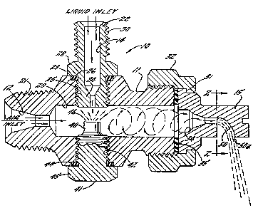
FIGURE 1 is a longitudinal s~ctional view of an
illustrative spray nozzle assembly embodying the
present invention; and
FIGo 2 is a vertical section of the tip of the
illustrative spray nozzle shown in FIG. 1, taken in
the plane of line 2-2,
~ hile the invention is susceptible of various
modifications and alterna~ive constructions, a
certain preferred embodiment has been shown in the
drawings and will be described below in detail. It
should be understood, however, that there is no
intention to limit the invention to the specific form
described but, on the contrary, the intention is to
cover all modifications, alternative constructions
and equivalents falling within the spirit and scope
of the invention.
Reerring now more particularly to FIGURE 1 of
the drawings, there is shown an illustrative spray
nozzle assembly 10 embodying the present invention.
The spray nozzle assembly 10 includes an elongated
hollow nozzle body 11 having an air inlet orifice 12
formed in one end of the body, a liquid inlet orifice
14 disposed at a side of the body, in thi~ in~tance
located in perpendicular relation to the air inlet

~ t- ~
- 3
orifice 12, and a nozzle tip 15 mounted on an end of
the body opposite the air inlet orifice 12. The air
inlet orifice 12 extends into the nozzle body 11 in
inwardly tapered fashion and communicates with an
enlarged diameter mixing and atomizing chamber 20
which extends longitudinally through the remainder of
the nozzle body. The air inlet orifice end of the
nozzle body 11 is formed with external threads 21 for
receiving an appropriate pressurized air supply lineO
The li~uid inlet orifice 14 in this instance is
defined by a fitting 22 that has an inner end 24 in
threaded engagement with a radial bore 25 that
extends through a side wall of the nozzle body 11 to
the chamber 20. An O-ring seal 26 is interposed
between a radial mounting flange 28 of the fitting 22
and an annular seat 29 in the nozzle body 11. The
fitting 22 has an outwardly extending end formed with
external threads 30 upon which an appropriate liquid
supply line may be mounted. In the application of
agricultural chemicals, a liquid, such as water,
cotton seed oil, soybean oil, or other liquid carrier
with which the chemical or chemicals to be applied
are mixed, would be supplied to the liquid inlet
orifice 22, which has an inwardly tapered
configuration and communicates with the chamber Z0.
For mounting the nozzle tip 15 on the nozzle
body llr the tip 15 is formed with a peripheral
flange 31 which is clamped against the end of the
nozzle body 11 by a clamp nut 32 that threadedly
en~ages the discharge end of the nozzle body 11. The
nozzle tip 15 i5 formed with a discharge orifice 34
that communicates with the discharge end of the
nozzle body chamber 20, and an annular seal 35 i5
interposed between the nozzle tip 15 and body 11 to
seal the perimeter of the tip.

~ r~
In accordanc~ with the invention~ transversely
directed streams of pressuri2ed air and liquid enter
and converge in the mixing and atomizing chamber of
th2 noz~le body causing preliminary atomization of
the liquid, which is thereupon directed under the
force of the high velocity air stream out of the
nozzle discharge orifice and against a deflector
flange of the nozzle tip which further atomizes the
liquid and directs into a well-defined, flat fan
spray pattern with uniform distribution and liquid
particle size. To this end, as illustrated in FIG.
1, a high velocity air stream directed through the
air inlet orifice 12 passes longitudinally into and
through the mixing and atomization chamber. At the
same time, liquid directed through the li~uid inlet
orifice 14 enters the chamber transversely to the
high velocity air stream such that the liquid and air
streams converge within the chamber 20.
To facilitate atomization of the converging
liquid and air streams in the mixing and atomizing
chamber 20, the chamber 20 has an inwardly extend;ng
impingement post or table 40 disposed in
diametrically opposed relation to the liquid inlet
orifice 14. The post 40 in this case is formed at
the terminal end of a screw member 41 in threaded
engagement with a rad.ial bore 42 in the side wall of
the nozzle body 11. An O-ring seal 44 again is
interposed between an exterior mounting flange 45 of
the screw member 41 and the nozzle body 11 for
insuring a proper seal therebetween. The post 41 in
this case defines a flat, circular impingement face
46 disposed in spaced relation to the outlet of the
liquid inlet orifice 14. The screw member 41 is
fixed in the nozzle body 11 so as to locate th~
impingement face 46 approximatel.y on the longitudinal

- 5
axis of th~ chamber 20 so that as liquid contacts the
impingement face, it will be swept by the jet stream
of pressurized air entering the chamber from the air
inlet orifice 12. The liquid stream is thereby
broken down into an atomized mixture with the air by
the combined action of striking the impingement face
46 and being exposed to the high velocity air stream
which induces turbulence to the resulting liquid
particles, which continue to mix with the air stream
as they are carried through the chamber 20 and
discharge orifice 34 of the nozzle tip 15.
In carrying out the invention, the nozzle tip 15
is formed with a deflector flange 50 disposed
transversely to the line of travel of the liquid
particles entering the discharge orifice 34 such that
the particles forcefully strike the~deflector flan~e
and are further broken down and atomized into small
particles of relatively uniform size, which are
thereupon directed into a well-defined flat fan spray
pattern transv rse to the axis of the nozzle body
11. The deflector flange 50 in this instance hac. a
signi~icantly greater width "w" than the outlet of
the discharge orifice 34 and defines an arcuate
shaped deflective surface which commences at the
outlet of the discharge orifice 34 and proceeds in
curved fashion to a terminally llp 50a tran~versely
offset from discharge orifice 34. While the
deflector flange 50 effectively enh~nces atomization
of the discharging spray, the arcuate configuration
of the flange is believed to to permit better control
of the spray pattern, such that the finely atomized
liquid particles form a well-defined pattern of
relatively narrow width and are distributed
relatively uniormly as a mist throughout the
pattern.

J~
-- 6 --
The nozzle assembly 10 of the present invention
has been found to operate with a number of unexpected
advantages. First, the nozzle efEects a discharge
with improved uniformity in spray distribution and
particle size, and such characteristics similarly are
achieved when viscous liquid materials, such as
cotton seed oil, soybean oil, petroleum based
products, or the like, are utilized as a liquid
carrier for agricultural chemicals. The nozzle
assembly further has been found to operate
efficiently in such manner at relatively low
pressures, such as on the order of 5 to 10 psi, and
at low flow rates At the same time, particle size
and spray distribution may be varied with a high
degree of control by controlliny the air supply~ The
relatively simple construction of the nozzle not only
facilitates economical manufacture, but has permitted
the application of viscous liquid carriers without
nozzle clogging or other maintenance problems which
here~ofore have plagued nozzles utilized for such
purpose. Hence, the nozzle of the present invention
has been found to have particular utility in the
application oE agricultural chemicals, although it is
understood that it may be used for other spray
applications. It will also be appreciated that while
the nozzle tip has been shown in the illustrated
embodiment as a separate removable part from the
nozzle body, alternatively, the discharge orifice and
deflector flange could be made an integral part of
the nozzle body.

Dessin représentatif
Une figure unique qui représente un dessin illustrant l'invention.
États administratifs

2024-08-01 : Dans le cadre de la transition vers les Brevets de nouvelle génération (BNG), la base de données sur les brevets canadiens (BDBC) contient désormais un Historique d'événement plus détaillé, qui reproduit le Journal des événements de notre nouvelle solution interne.

Veuillez noter que les événements débutant par « Inactive : » se réfèrent à des événements qui ne sont plus utilisés dans notre nouvelle solution interne.

Pour une meilleure compréhension de l'état de la demande ou brevet qui figure sur cette page, la rubrique Mise en garde , et les descriptions de Brevet , Historique d'événement , Taxes périodiques et Historique des paiements devraient être consultées.

Historique d'événement

Description Date
Inactive : CIB expirée 2022-01-01
Inactive : Renversement de l'état périmé 2012-12-05
Le délai pour l'annulation est expiré 2006-11-07
Inactive : CIB de MCD 2006-03-11
Lettre envoyée 2005-11-07
Accordé par délivrance 1989-11-07

Historique d'abandonnement

Il n'y a pas d'historique d'abandonnement

Historique des taxes

Type de taxes Anniversaire Échéance Date payée
TM (catégorie 1, 8e anniv.) - générale 1997-11-07 1997-10-17
TM (catégorie 1, 9e anniv.) - générale 1998-11-09 1998-10-20
TM (catégorie 1, 10e anniv.) - générale 1999-11-08 1999-10-18
TM (catégorie 1, 11e anniv.) - générale 2000-11-07 2000-10-18
TM (catégorie 1, 12e anniv.) - générale 2001-11-07 2001-10-17
TM (catégorie 1, 13e anniv.) - générale 2002-11-07 2002-10-17
TM (catégorie 1, 14e anniv.) - générale 2003-11-07 2003-10-16
TM (catégorie 1, 15e anniv.) - générale 2004-11-08 2004-10-07
Titulaires au dossier

Les titulaires actuels et antérieures au dossier sont affichés en ordre alphabétique.

Titulaires actuels au dossier
SPRAYING SYSTEMS CO.
Titulaires antérieures au dossier
JAMES HARUCH
Les propriétaires antérieurs qui ne figurent pas dans la liste des « Propriétaires au dossier » apparaîtront dans d'autres documents au dossier.
Documents

Pour visionner les fichiers sélectionnés, entrer le code reCAPTCHA :


Pour visualiser une image, cliquer sur un lien dans la colonne description du document. Pour télécharger l'image (les images), cliquer l'une ou plusieurs cases à cocher dans la première colonne et ensuite cliquer sur le bouton "Télécharger sélection en format PDF (archive Zip)" ou le bouton "Télécharger sélection (en un fichier PDF fusionné)".

Liste des documents de brevet publiés et non publiés sur la BDBC .

Si vous avez des difficultés à accéder au contenu, veuillez communiquer avec le Centre de services à la clientèle au 1-866-997-1936, ou envoyer un courriel au Centre de service à la clientèle de l'OPIC.


Description du
Document 
Date
(aaaa-mm-jj) 
Nombre de pages   Taille de l'image (Ko) 
Revendications 1993-09-14 4 147
Abrégé 1993-09-14 1 32
Page couverture 1993-09-14 1 14
Dessins 1993-09-14 1 38
Description 1993-09-14 6 243
Dessin représentatif 2001-08-09 1 28
Avis concernant la taxe de maintien 2006-01-03 1 172
Taxes 1996-10-18 1 78
Taxes 1995-10-20 1 67
Taxes 1994-10-20 1 72
Taxes 1993-10-18 1 58
Taxes 1992-09-15 1 64
Taxes 1991-10-15 2 91