Note : Les descriptions sont présentées dans la langue officielle dans laquelle elles ont été soumises.
1~t~3~73
ISOTROPIC ACOUSTIC WAVE SUBSTRATE
BACKGROUND OF THE INVENTION
This invention relates generally to acoustic
wave devices~ and more particularly, to substrate
materials for use in surface acoustic wave (SAW)
devices. These devices employ substrates of a piezo-
electric material, across which elastic surface waves
are propagated between sets of electro-acoustic trans-
ducers disposed on the substrate surface. The devices
employ so-called Rayleigh waves, which can be propa-
gated along a free surface of a solid, and have an
amplitude of displacement that is largest right
at the substrate surface. In a piezoelectric material,
deformations produced by such waves induce local
electric fields, which are propagated with the acoustic
waves and extend into space above the surface of the
material. These electric fields will interact with
electrodes disposed on the surface of the material, to
serve as electrical input and output transducers for
the surface acoustic wave device.
Substrates for SAW devices are usually highly
anisotropic in nature, i.e. the velocity of wave
propagation varies strongly with the direction of
propagation. SAW devices, therefore, usually employ a
single direction of wave propagation.
.,
i~634'73
--2--
It is well known that surface acoustic waves
behave analogously to light waves in many respects. In
particular, interference and diffraction effects in optics
have counterparts in surface acoustic wave technology.
However, SAW devices employing principles of interference
or diffraction are required to transmit waves in more than
one direction. If the SAW substrate is anisotropic, the
only way to implement interference or diffraction devices
in SAW technology is by compensating for the velocity
differences by appropriate positioning of the transducers.
This approach is used, for example, in apparatus disclosed
in U.S. Patent No. 4,541,687 issued on September 17, 1985
to Robert E. Brooks (assignor to TRW Inc.).
If diffraction and interference effects can be
exploited directly in SAW devices, powerful signal
processing functions may be implemented, such as spectrum
analysis and Fourier transformation. Ideally, however,
these functions require almost perfectly isotropic
substrates, to permit the use of transducer patterns that
are acoustically correct for a wide range of propagation
directions at each point on the surface. Lead zirconium
titanate (PZT) and zinc oxide (ZnO) are horizontally
isotropic materials that have been available for this
purpose, but their performance at high frequencies, above
60 megahertz (MHz), is poor. Trigonal materials that are
in most respects highly suitable for use in SAW devices,
such as quartz and lithium niobate (LiNbO3), have long
been known to be highly anistropic in nature, and hence
not suitable for devices employing diffraction or
interference principles. Specific cuts of lithium niobate
crystals have been recognized as being less likely to
propagate bulk sheer waves. For example, Pat. No.
4,409,571 to Milson et al is concerned with selection of
lithium niobate to minimize bulk waves.
;
: - ' ,~ ,
~' ' ,
. .
:
. .
.
4~73
It will be appreciated from the foregoing that
there is a need for a high-quality isotropic SAW
substrate, havlng low propagation loss, low cost, a high
coupling coefficient, and excellent uniformity.
Preferably, these desirable properties should also be
obtainable at high frequencies. The present invention
fulfills this need.
SUMMARY OF THE INVENTION
The present invention resides in the use of a
substrate material of X-propagating, 121-degree
Y-rotated-cut lithium niobate, to minimize anistrophy.
Basically, the invention is a structure for use in a
two-dimensional diffraction-effect or interference-effect
surface acoustic wave (SAW) device. The structure
comprises a substantially isotropic SAW substrate of
X-propagating rotated Y-cut lithium niobate (LiNbO3)
having a Y rotation angle of approximately 121 degrees,
and a plurality of electro-acoustic transducers disposed
on a surface of the substrate at substantially different
angles relative to the principal X propagation direction,
thereby directly exploiting the diffraction or
interference properties of acoustic waves.
The invention may also be expressed as a method
of manufacturing surface acoustic wave (SAW)
diffraction-effect or interference-effect devices.
Basically the method comprises the steps of cutting a
crystal of X-propagating lithium niobate (LiNbO3) at a
rotated-Y-cut angle of approximately 121 degrees, to form
a SAW substrate, and forming a plurality of
electro-acoustic transducers on a surface of the
substrate, aligned to transmit or receive acoustic waves
propagated at various angles that may differ substantially
from the principal X propagation direction.
'7'3
--4--
For the specific cut of lithium niobate
required by the invention, the SAW velocity varies by
only about 25 parts per million for angles of propaga-
tion between +5 and -5 degrees of the X axis. More-
over, the coupling coefficient is relatively high forSAW devices, and the material can be produced at
relatively low cost.
It will be appreciated from the foregoing
that the present invention represents a significant
advance in the field of SAW devices. In particular,
the invention provides a substrate material that is
practically isotropic, but also has a high coupling
coefficient and low losses, and can be made at rela-
tively low cost. Other aspects and advantages of the
invention will become apparent from the following more
detailed description, taken in conjunction with the
accompanying drawings.
BRIEF DESCRIPTION OF THE DRAWINGS
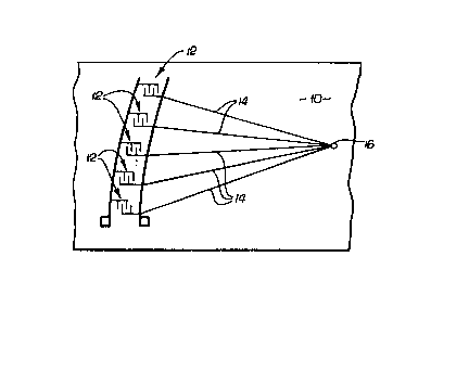
FIGURE 1 is a plan view of a portion of a
substrate having multiple transducers for propagating
surface acoustic waves in different directions; and
FIG. 2 is a graph showing the anisotropy
coefficient as a function of Y rotation cut angle in
lithium niobate.
DESCRIPTION OF THE PREFERRED EMBODIMENT
As shown in the drawings for purposes of
illustration, the present invention is concerned with
surface acoustic wave (SAW) devices. The most useful
and widely used substrate materials for SAW devices are
anisotropic, meaning that their elastic properties are
not the same for all directions of wave propagation.
i,.~;34~3
--5--
Specifically, the velocity of wave propagation varies
strongly with the direction of propagation. For this
reason, SAW devices have not been widely used as
diffraction-effect or interference-effect devices,
since these require either almost perfect isotropy, or
the use of elaborate compensation techniques.
In accordance with the invention, a specific
cut of lithium niobate is used as the substrate materi-
al, to obtain practically perfect isotropy over a
fairly wide range of propagation directions. FIG. 1
shows a SAW substrate, indicated by reference numeral
10, and a plurality of transducers 12 disposed on a
surface of the substrate 10 to transmit surface acous-
tic waves propagated in different directions with
respect to a principal direction of propagation. By
way of example, the transducers 12 may be relatively
small in size, and may function as point sources of
acoustic energy. The lines 14 in FIG. 2 indicate
propagation paths to a focal point 16. This is the
type of configuration used in a diffraction device.
The transducers 12 may, of course, be aligned in
specific direc,ti~ons ~for some ~pli~cations of diffrac-
tion-effect or intcrfcrcncccffcct devices.
The SAW velocity of propagation for rotated
Y-cut, X-propagating lithium niobate can be expressed
approximately as a quadratic function of the propaga-
tion angle, as follows:
V = Vo(l + (y/2)02),
where 0 is the deviation frvm the X-axis direction in
radians, V0 is the velocity in the X-axis direction,
and Y is the anisotropy coefficient. For a zero
anisotropy coefficient, the angle of propagation
direction has no effect on the propagation velocity.
FIG. 2 shows how the anisotropy coefficient
varies with the angle of Y-rotated cut in X-propagating
473
--6--
lithium niobate. The coefficient passes through zero
at a rotation angle of 121 degrees. For this angle of
cut, the velocity of propagation varies by only about
25 parts per million over a range of propagation
directions between +5 and -5 degrees with respect to
the X axis. The coupling coefficient k2 is approxi-
mately 4.3% for this cut of lithium niobate, which is a
relatively high value for ~AW substrates. Also,
lithium niobate has a relatively low attenuation loss,
approximately 2.6 dB/cm at 1 GHz. Moverover, since
lithium niobate is routinely grown in large boules, the
substrate of the invention can be produced at rela-
tively low cost.
It will be appreciated from the foregoing
that the present invention represents a significant
advance in the field of surface acoustic wave devices.
In particular, the invention provides for the first
time an isotropic substrate material with low losses
and a high coupling coefficent. The material can,
therefore, be used in diffraction-effect and inter-
ference-effect devices without the need for cumbersome
compensation techniques. It will also be appreciated
that, although the invention has been described in
detail for purposes of illustration, modifications may
be made that are still within the scope of the appended
claims.