Note : Les descriptions sont présentées dans la langue officielle dans laquelle elles ont été soumises.
PlLN 11 416 1 2-9-19.~5
"Optical scanning unit comprising a translational-positiion
and angular-position detection system .for an electro-
magnetically suspended objeetive"~
The invention relates to an optical seanning
unit comi~rising a rad~tion source, an objective lens for
.~ocussing a ra~iatio-.l be~n produced ~y the radiation source
to form l scal~ning spot on a surface to be scanned, a
trainslational-position and ~ngular-position deteetion
system for deteeting the translational positions of
t~le objeetive lens along and the angular positions of
said lens about two orthogonal axes whieh both extend
perpendicularly to the chief ray of the radiation beam,
and an aetuating device for translating and tilting -the
objective lens in response to the electric control signals
supplied by the transla~o~-position and angular-position
deteetion system. The invention also relates to apparatus
fo~ reading and/or recording information in an information
surface of an optical record earrier1
The terrn "objeetive lens" must be interpreted
in its widest sense. Sueh a lens may eomprise a plurality
of lens element but rnay alternaiively cor~prise a single
lens element having,. for example, one or two aspheric
surfaees. Alternatively, the objective lens may be, for
example, a holographic lens or another lens whose
operation is based on diffraetion instead of refraetion.
United States Patent Speci~ieation no. 4,425,043
deseribes a~l optieal seallning unit for use in an apparatus
for reading and/or inseribing an optieal reeord earrier,
in whieh sealming unit the oojeetive lens with its holder
is suspended in an electroLIagnetic syster.l. This system
ensures that the objective lens substaltially follows the
mOVemelltS Of the sca~ning unit, in other words oeeupies
a .substantially fixed position in the seanning unit,
without physical eontact between this lens and the other
elements of the seanning unit, i.e. the objeetive lens
is floating~ As a result of this, the position or the
~d~
~ 7 ~
PXN 11 416 -2- 2-9-1985
movement of the oojective lens ca~not be influenced by
undesired resonances, which resonances do play ~ p~t if
the objective lens is suspended in the scanning unit by
means of, ~or example, mechanical o- elastic means. Sus-
pend-ing or supporting the objective lens electromagnetical--
ly is very bene~`icial for the stability of the scanning
spot formed by the o~jective lens.
When the objective lens is required to be capable
of following movements or vibrations of the sca-nning unit
steps must be t~ken to enable the translational position
of the objective lens relative to the chief ray of the
radiation be~m and the angular position of the optical
axis of this lens relative -to the direction of the chief`
ray to be detected and these positions to be corrected~
Europea~ Patent Application no. O,O7~,~7O, which
has been laid open to public inspection,describes some
examples of an electromagnetic suspension system for an
objective lens in which the magnet coils of the systems
are controlled by translational-position and angul~r-
pOSitiOll signals in such a way that during operation of
the apparatus the objective lens is not only kept floating
but is also set to the correct translational position
and angular position. In order to obtain the control
signals necessary for this, a re~lecting prism May be
arranged on the circumference of the objective lens or its
mo-lnting in accordance with the above-mentioned United
States Patent Speci~ication no. 4,425,o43. This prism
forms part of a separate translational-position and
angular-position detection system, which further comprlses
a radiation source and a radiation-sensitive detection
systen comprising at lea;t for separate detections. The
prism reflects the beam emitted by -the radiation source
to the detection system and splits this beam into two
sub-beams wllich are each received by a separate set ~ at
least two detectors.Tne radiation~distribution over the
two sub-be~ns and hence the detector output signals are
determined by the translational position and the an~llar
position o~ th ~rism and, consequently, of the objective
P~ 11 416 -3- ~_9-1985
lens relative to the fixed position and orientation of the
radiation be~n.
The ~lown trar.slational-position and angular-
pOSitiOll detection s~tem requires some extra provisions
such as an additional radiat.ion so-.Lrce. Moreover, the
systam may exhib:it cross-talk between the various detector
signals a~d hence between the various cont:rol loops, which
may render the entire translational-position and angular-
position detection system unstableq Further~ the ~lown
translation-position and angular-position detaction system
can be operative only for a speci~ic pos~io~ of ~h~
prism, viewed in a plane tr~lsverse to the optical axis
of the objective lens. In the known system it is nscessary
either to ens-lre that the object:ive lens cannot rota-te
about its O~l axis or to provide an additional detector
f`or detecting the rotation of the prism about the object-
ive axis so as to enable the pOSitiOIl of the prism to be
corrected,
It is an object of the present invention to provide
a translat~-positio:n and angular-position detection
system which enables an independent measurement of the two
tran.slations and two pivotal movements of the object lens
to be made, which requires only a small nwnber of simple
provisions in the scannin~ Wlit, and which is not in-
fluenced by a rotation of the objective lens about itsaxis. To this end the invention is characterized
in that the tran.slational-position and angular-position
detection system comprises a conical-ring Mirror which is
centred and fixed relative to the objective lens and a
radiation-sensitive detection system which is arranged in
the path of the radiation re~lected from the mirror and
which comprises two detectors which are spaced by an
annulal- strip and are each divided into ~our quadrants.
For detecting the transl ~ ~al position and the
angular position of the objective lens use is made of
that part of the rad-iation from the radiation source of
the apparatus which does not fall within tne pupil of the
o~jective lens and does not contribllte to tne scanning
~L2~i37~7
pH~T 1I L~ 9_19~5
spot, so that it is not necessary to provide a separate
radiatiol ~O~lr o ~`or p~ lete(lioJl purpos~s. lhis
radiation is re-~lected by the conlcal mirror to f`orm an
anrlular rad-ation spot whose average diameter is in con-
formity with that of the annul~r strip of the radiation-
sensitive detection system. This system has a simple shape
and can be integrated on one substrate~ The tilts of the
conical mirror and hence of the objective lens about the
two axes transverse to the chief ray of the radiation
beam and the displ~cement o~ the conical mirro~ alon~
these axes each cause a different displacement of the
intensity centre of the radiation distribution over the
detection s~tem, so that these displacements and tilts
can be detected independently of one another. A rotation
of the conical mirror about the chief ray of the beam
has no effect on the detector signals because the conical
mirror is ring-shaped.
An essential feature of the invention is that
the conical-ring mirror has a fixed translational position
and angular position relative to the objective lens. ~n
embodiment of the optical scanning unit may be character-
ized further in that the conical-ring mirror is an element
which is connected to the holder of the objective lens.
Another embodiment of the scanning unit is
characterized in that the conical-ring mirror is con~
stituted by a bevelled raised edge position of a lens ele-
ment of the objective lens; which raised edge portion is
provided with a reflecting layer. ~n this embodiment
the raised edge portion of said lens element, which may be
the sole e7ement of the objective lens, may already be
formed during the manufacture of this lens element, so
that this raised edge portion merely has to be provided
with a reflecting layer.
For reasons of weight and cost an objective lens
of an optical scanning unit preferably comprises only
one lens element. Such a lens ~s required to have one or
two aspheric refracting surfaces. Manufacturing such a
lens element in large quantities at acceptable costs
12~i3747
PHN 11 416 _5_ 2-9-1985
is possible only if use is made of a lens die whose inner
surface pro~ile is the negative oI` the desired profile cf
the lens surface. By means of such dies it is possible to
manufacture lens elements which are entirely made of a
transparent plastics. However, it is preferred to use a
glass preform on which a plastics in an adequately soft
condition is deposited and which is given the re~uired
shape by means of a lens die, after which it is allowed
to cure. This plastics may be an ultraviolet-curable
synthetic resin9
A preferred embodiment o~ the optical scanning
unit, in which the objective lens comprises one lens
element in the f`orm of a transparent body whose surf`ace
which faces the radiation source is provided with a
plastics layer having an aspheric outer prof`ile, is
characterized further in that the raised edge portion con-
sists of the said plastics.
The scanning unit may be characterized further
in that the detectors of the radiation-sensitive detection
system are annular. Since the surface areas of the
detectors are now small, these detectors respond rapidly
and the transl~a~-position and angular-position detec-
tion system is more immune to spurious radiation as a
result of, for example, undesired re~lections in the
scanning unit.
By the use of the translation-position and
angular-position detection system in accordance with the
invention it is possible to keep an objective lens which
is suspended in the magnetic field accurately f`ixed in its
translational and angular position if the scanning unit is
provided with actuating means which convert the servo
signals supplied by the translationa~-position and
angular-position detection system into displa~ements and
tilts of the objective lens.
Another aspect of the invention therefore relates
to a combination of the translationa~position and angular-
position detection system with an electrom3gnetic
actuating device specifically intended for this purpose.
~2~3'747
PHN 11 416 -6- 2-9~1985
In accordance with this aspect, the scanning unit is
characterized in that the actuating device comprises an
annular permanent magnet which is fixedly connected to the
objective lens and two sets of at least three stationary
magnet coils each, the coils of the first set being
arranged in a first plane transverse to the chief ray of
the radiation beam and the coils of the second set being
arranged in a second plane parallel to the first plane.
This actuating device ~so enables the axial
position, i.e. the position along the chief ray of the
radiation beam, and hence the focussing of the objective
lens to be corrected, Such a correction is required when
a disc-shaped record carrier is 9ca~ned and the axial
distance between the scanning device and the point of
the information surface being scanned can vary. The
focussing-control signal is supplied by a focussing-error
detection system which is already present in a conventional
scanning unit, and not by the translational-position and
angular-position detection system for the objective lens.
The variation in axial distance between the in-
formation surface and the scanning unit may be comparative-
ly lar~e, which means thatcorrections of the axial position
of the objective lens should be possible over a com-
paratively wide range. A larger displacement of the ob-
jective system and the annular magnet out of the axial
symmetrical position between the two sets of ma-~net coils
may have the result that, when specific coils are ener-
gized in order to obtain a specific displacement of a
specific tilt of the objective lens, in addition to the
force in the desired direction undesired forces in other
directions may occur, because the forces in the undesired
directions produced by the magnet coils no longer cancel
each other. This may give rise to crosstalk, referred to
hereinafter as actuator cross-talk, which differs from
the crosstalk between the detector signals mentioned at
the beginning of the present description, referred to
hereinafter as detector crosstalk.
~n order to reduce actuator cros~talk the
~263~747
PHN 11 416 -7- z-9-1985
scanning unit in accordance with the invention may be
characteri~ed further in that there is provided an
axial-position detection system f~r ~etecting the position
of the objective lens along the chief ray of the radiation
beam and in that the signal supplied by said detection
system is applied to the magnet coil. This ensures that
the current through each rnagnet coil and hence the force
generated by this coil, is corrected for, or weighted
with, the actual axial position of the objective lens and
the annular magnet relative to the axial centre positio
midway the two planes of the magnet coils.
A preferred embodiment of the scanning unit is
characterized in that the axial-position detection system
comprises a signal generator for supplying a first con-
trol signal to the first set of magnet coils and asecond control signal to the second set of magnet coils,
which signals have the same amplitude and frequency but are
in phase opposition and cause the objective lens to be
tilted periodically about one of the two axes transverse
to the chief ray of the rad~tion beam, and in that the
axial-position detection system further comprises the
elements of the translational-position and angular-position
detection system for converting the periodic tilting into
a periodic signal who~ amplitude and phase are represen-
tative of the magnitude and the direction of a displacementof the axial centre of the annular magnetout of a plane
which is situated midway between the two planes in which
the magnet coils are disposed.
The additional detection function is t~en ob-
tained by means of a minimal number of additional elementsand an optimum use is made of provisions which are
_already present in the scanning unit.
The optical scanning unit is very suitable for
~se in an apparatus for reading and/or recording informa-
tion in an information surface of a round disc-shaped
record carrier. Such an apparatus may be characterized
in that a separating element i3 arranged between the
objective lens and the radiation source for separating
~Z~;3~ 7
PHN 11 416 -~ 2-9-1985
the radiation reflected by the conical ring mirror from
the radiation emitted by the racliation source.
The radiation which emerges from the opening in
the conical ring mirror may be used for the actual
s scanning of, for example, a disc-shaped record carrier.
This record carrier may have a radiation-transmitting or
a radiation-reflecting information surface. In the latter
case the radiation reflected by the information surface
can be directed to a radiation-sensitive information
detector via said separating element. This information
detector, which may comprise a plurality of sub-detectors,
may be arranged at another location than the radiation-
sensitive detection system of the translational-position
and angular-position detection system. Ho~ever~ preferably
a radiation-sensitive detector is arranged inside the
annular inner detector of the translation-position and
angular-position detection system, for converting the
radiation reflected by the information surface into an
electric signal~ In addition to the information being
read, this signal may contain information on the position
of the scanning spot relative to an information track of
the record carrier.
The invention will now be explained by
describing, by way of example its use in an apparatus
for reading and/or inscribing an optical record carrier.
Reference is made to the drawings, in which:
Fig. 1 shows a read apparatus provided ~ith a
translational-position and angular-position detection
system in accordance with the invention,
Fig. 2 shows the composite radiation-sensitive
detector of this system,
Fig. 3 shows an electronic circuit for processing
the signals from this detector,
Pig. 4 shows an objective lens with an integrated
conical-ring mirror,
Fig. 5 is a plan view of an example of an elec-
tro-magnetic suspension system,
Fig. 6 is a cross-sectional view of this system,
7d~7
Pl~ 11 416 -9- 2-9-1985
and
Fig. 7 illustrates how an axial~position signal
ror the objective lens can be obtained.
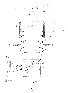
The scanning unit sho~m in Fig~ 1 comprises a
radiation source 1, for example a diode laser, a colli-
mator lens 2 and an objective ]ens 3~ which is mounted in
a holder 4. Both the collimator lens and the objective
lens may comprise a plurality of lens elements, but
preferably they comprise a single lens element having
at least one aspheric refracting s~rface.
The diver~ing read beam b emitted by the r~di~tion
source is converted into a parallel beam by the collimator
lens, which beam fills the aperture of` the objective
lens 3 in adequate manner. The objective lens focusses
the read beam to form a diffraction-limited radiation spot
V having a diameter of, for example, 1 /um on the infor-
mation surface 31 of a disc-shaped record carrier 3O~ of
which a small part is shown in radial cross-section in
Fig. 1. The information is arranged in concentric tracks
33 or quasi-concentric tracks which together constitute
a spiral track. This information comprises a multitude of
optically detectable information areas, not shown~ which
alternate with intermediate areas. Suitably, the informa-
tion surface 31 is situated on the upper side of the
record carrier, so that the read beam b traverses the
transparent substrate 32 of the record carrier before it
reaches the information surface. Further, the information
surface is suitably radiation-reflecting, so that the read
beam is reflected towards the radiation snurce.
~s the record carrier is rotated relative to
the scanning unit the beam which is reflected by the in-
formation surface is time-modulated in conformity with the
sequence of information areas and intermediate areas
in an information track to be read. In order to separate
the modulated beam from the beam which is emitted by the
radiation source a separating element 6 is arranged in
the radiation path, which element may be, for example, a
semitransparent mirror or a be~-splitting prims, which
12637~7
PHN 11 416 -10 2-9-1985
may be polarization sensitive or not and whose interface
7 reflects at least a part of the radiation to the
radiation-sensitive information detector 11. The infor-
mation detector in the form of for example a photodiode,
is suitably arranged in a plane 10 which coincides with
the diode-laser exit face which is mirror-inverted rela-
tive to the interface 7. The information de-tector 11 con-
verts the modulated read beam into an electric signal
which is processed in known mam-ler to form a signal which
is suitable for being displayed, reproduced or processed
in another manner depending on the type of information
stored in the record carrier. The nature of the information
and the processing of the signal from the information de-
tector fall beyond the scope of the present invention and
are not discussed in more detail.
In order to enable the objective lens 3 to
follow the movements of the scanning unit without any
physical contact between this lens and the other elements
of the scanning unit the objective lens is suspended in
an electromagnetic system which will be described in more
detail with reference to Figs. 5 and 6. This requires the
use of a translational-position and angular-position
detection system for measuring deviations between the
centre M of the objective lens and the chief ray L of
the beam b along an X-axis in the plane of the drawing
and along an Y-axis perpendicular to the plane of the
drawing and tilts of the objective lens about these two
axes, so that such deviations from the translational
position and the angular position can be eliminated by
means of a control system.
The origin of the XYZ axial system shown in the
right-hand part of Fig. 1 is in reality situated in the
point M, so that the Z-axis coincides with the chief ray
L. The direction along this axis may also be referred to
as the axial direction. The tilt of the object lens about
the X-axis may be represented by the tilting angle ~ and
that about the Y-axis by the tilting angle ~ . The X
a~is and the Y-axis extend, for example, in the infor-
~26374~
PHN 11 416 -11- 2-g-1985
mation plane, p~rallel to the radial direction and the
tangential direction respectively~
In accordance with the invention the translational
-position and angular-position detection system comprises
a ring mirror 5 which is fixedly connected to the objec-
tive lens which mirror is also conical, i.e.the reflect
ing surface i9 disposed at an angle which differs f`rom
to the chief ray L, and a radiation-sensitive detect-
ion system 9 which is arranged in the plane 10 and wh:ich is
shown in ~ront view in Fig. 2, i.e. in a section taken
on the line II-II' in Fig. 1. The conical ring mirror 5
reflects that part of the radiation beam b which falls
within the aperture 8 but oitside the pupil of the objecti-
ve lens to the separating element 6, which in its turn
reflects a part of the radiation to the detection system
9. An annular radiation pattern is formed on this system.
The radiation-sensitive detection system 9 comprises two
detector rings which are spaced by an intermediate ring
12 and which each comprise four detectors 13, 14, 15, 16 --
20 and 17, 18, 19, 20 respectively. The annular radiation
pattern is represented by the dashed circles 21 in Fig. 2.
The average diameter of this radiation pattern is equal to
that o~ the intermediate ring 12.
The radiation distribution of the pattern among
the eight detectors depends on the translational position
and the angular position of the conical-ring mirror 5
and, consequently, of the objective lens 3. A tilted
position about the X-a~Yis or the Y-a~Yis results in the
annular radiation pattern 21 being shifted in the direct-
ion indicated by the arrow 22 and the arrow 23 respective-
ly. A shift of the mirror 5 along the X-a~Yis and Y-aYis
results in a change of the radiation distribution within
the annular radiation pattern in such a way that in the
case of a displacement along the X-axis the left-hand
part of the detection system will receive more radiation
or less radiation than the right-hand part, because the
portions of the two mirror halves which are situated
within the beam, which is stopped down by the aperture 8,
~263~747
PHN 11 416 -12- 2-9-1985
are no longer identical. Similarly, the upper part of
the detection system will receive more radiation or less
radiation than the lower part in the case of a movement
~ong the Y-axis.
I~ the signals from the detec-tors 13 to 20 are
represented by S followed by the corresponding indices,
the displacements along the X-axis and Y-axis and the
pivotal movements about these axes may be represented
by:
S = (S14 ~ S15 f S18 ~ S1~) ~ (S13 16 17 20
S = (S ~ S14 + S17 ~ S18) - (S1s ~ S16 ~ 19 20)
S(c = (S ~ S14 ~ S19 + S20) - (S17 + S18 15 1~
S~ = (S 4 + S1s + S17 ~ S20) ~ (S18 + S19 13 16
The individual detector signals can be processed to form
composite signals Sx, Sy7 S ~ and S ~ by means of an
electronic circuit, of which an example is shown in Fig.
3, The operation of the circuit, which comprises a number
af adder circuits (40 to 47 and 50 to 57) and a number of
subtractor circuits (48, 49, 58, 59), is evident from
the Figure and requires no further explanation. The com-
posite signals Sx, Sy~ S ~ and S ~ are independent of
each other and exhibit no mutual crosstalk, so that the
various displacements and tilting angles can be detected
independently of each other. A r~ation of the o~jective
lens about the Z-axis does not cause a change of the an-
nular radiation pattern 21 and consequently does not
influence the detector signals. Displacemen-ts of the ob-
jective lens along the Z-axis also do not have any in-
fluence on the radiation pattern 21.
In the scanning unit the signals are employed
for driving the magnet coils in an electromagnetic sus-
pension system. In this way the translational position and
the angular position of the objective lens are locked
to the translational position and the angular position of
the composite detector 13-20, which occupies a fixed
position within the scanning unit, so that during operation
of the read apparatus the objective lens is always con-
trolled to assume the correct translational position and
~2~7~7
PHN 11 41f) _13_ 2-9-1985
an~ular position within the scanning unit.
A requirement for this is that the conical ring
mirror has a fixed translational position and angular
position relative to the objective lens. For this purpose,
as is shown in Fig 1, the mirror 5 may form part of the
objective holder on mounting 4, within which the objective
lens is fixedly arranged. It is alternatively possible to
use a separate element for this mirror, which element is
secured to theexterior or interior of the objective holder.
A very attractive possibility o~ accurately locking ~he
translational position and the an~llar position of the
annular mirror 5 to those of the objective lens 3 is ob-
tained when this lens is manufactured in accordance with
a replica process. This possibility is illustrated in
Fig. 4.
It has long been known that in the scanning unit
described the objective lens comprising a plurality of
elements may be replaced by an objective lens comprising
only one lens element. However, instead of spherical
refractive surfaces this lens element should have aspheric
refractive surfaces in order to provide adequate correction
for lens aberrations. In order to enable such single
objective lenses with intricate surface profiles to be
manufactured in large quantities at an acceptable price,
it has already been proposed to employ a transparent
body or preform 60 of, for example, glass, having for
example two spherical refractive surfaces 61 and 62. A
plastics material in an adequately soft condition is
deposited on one of these surfaces or on both surfaces.
This plastics material may be a thermosetting plastics,
but alternatively it may be an ultraviolet-poly~erisable
synthetic resin. A~ter the plastics material has been
deposited on the surface a die whose surface profile is
the negative of the desired lens profile is pressed into
the material~ Subsequently~ the material is cured and
the die is removed, so that a lens provided with a plas-
tics layer 53 having an aspheric profile 64 is obtained.
Such lenses need not be subjected to any further operation
~2~i3747
PHN 11 4-l6 -14- 2~9-1985
such as polishingO
In accordance with the invention the die by means
of which the objective lens is manuf`actured can be
adapted in such a way that along with the aspheric layer
63 a raised edge portion 65 wi-th a bevelled surface 66
is formed. After the manufacture of the objective lens the
surface 66 merely has to be provided with a reflecting
coating 67, for example by vapour deposition, in order
to obtain an objective lens with an i~egrated conical-
ring mirror. The reflecting raised edge portion may be
formed on the lens surface which is situated nearest the
radiation source but alter~tively it may be formed on
the other lens surface.
Alt natively, the entire objective lens may be
moulded from a transparent plastics by means of dies
having the desired profile. The die used for manufactur-
ing a lens surface may be formed with a recess at its
edge so that the lens thus manufactured is formed with a
raised edge portion with a bevelled inner surface, If
a glass preform is used the first-mentioned replica lens
has the advantage that it is more immune to temperature
variations and other environmental inf`luences, such as
moisture.
It is obvious that the scanning unit may com-
prise an objective lens comprising a plurality of lens
elements and that the surface of the last lens which facesthe radiation source may have an aspheric surface and
carry an integrated conical ring mirror, Alternatively,
this mirror may be arranged on one of the other lens
surfaces.
As is shown in Fig, 1 the information detector
11 may be arranged inside the composite detector of the
translational-position and angular-position detection
system and may be integrated on one substrate together
with said system, using known and very accurate techno-
logics for the manufacture of integrated circuits. Theinformation detector may comprise a single detec$or which
only supplies the signal representing the information
~çj37a~7
PHN 11 416 -15- 2-9-1985
stored on the record carrier. Alternatively, the in-
formation detector may be divided into sub-detectors which
in addition to the information signal also supply control
signals, such as a tracking signalO
~ tracking signal can be obtained by dividing
the detector 11 into two sub-detectors 11a and 11b, as
indicated by the broken line ~5 in Fig. 2, which line
corresponds to the tangential direction on the record
carrier ~0. The difference between the output signals of
the sub-detectors 11a and 11b contain information on the
magnit~de and the direction of a deviation between the
centre of the read spot V and the cen-tre line of an in~
formation track to be read. The manner in which a
tracking signal can be generated falls beyond the scope of
the present invention and will not be described in more
detail. ~y way of example reference is made to United
States Paten-t Specification no. 4,~2~,043, where in
addition to the said method of generating a tracking signal
a method of generating a focussing error signal is
2G described.
In the scanning unit in accordance with the
invention it is possible, by analogy with the last-
mentioned method to separate a part of the main-beam
radiation reflected by the prism 6 from the main beam
i.e. the beam which is incident on the detector 11, for
example by means of a semitransparent mirror~ By means of~
for example, a roof prism the part thus separated can be
divided into two sub-~eams, which sub-beams are incident
on three or four radiation-sensitive detectors which are
arranged in line transversely of the roof edge of the
prism. The focussing-error signal is given by the
difference between the sum signal of the two outer de-
tectors and the sum signal of the two inner detectors.
In order to keep the radiation spot V centred
on an information track a read apparatus comprises a
coarse control and a fine control. For coarse control
purposes the scanning unit shown in Figo 1 may be moved
bodily in a radial direction relative to the record
747
PHN 11 416 -16- 2-9-1985
carrier. ~or this purpose the elements 1, 2, 3, 6, 9 and
11 may be arranged inside one tubular holder, which is
radially movable by means of a pivotal arm or a recti-
linearly movable slide. Fine control may be effected~ for
example, by means of a pivotal mirror, not shown in ~ig.
1, or by mo~ing the objective lens over small distances
in the X-direction or the radial direction. As described
in United States Patent Specificat~o~ no. 4,423,496 this
fine control results in the chief ray L of the read beam
being displaced relative to the detectors 11a and 11b
independently of the deviation ~etween the centre of the
radiation spot V and the centre line of a track being
read. This introduces an error, referred to as offset,
into the tracking signal. As is described in United
15 States Patent Specification no. 4,L~23,496 this error can
be eliminated by correcting the tracking sig~al obtained
by means of the detectors 11a and 11b using a signal which
is proportional to the radial position of the objective
lens. In a scanning unit according to the invention this
signal Sx is already supplied by the translational-
position and angular-position detection system, so that
unlike apparatuses in accordance with United States Patent
Specification no. 4,423,496 no separate system is required
for this purpose.
When an optical record carrier having a
radiation-reflecting information surface is read by means
of a diode laser use can be made of the feedback effect
of such a laser. The beam which is modulated by the in-
formation structure is then not separated from the beam
emitted by the diode laser but the first-mentioned
beam re-entsrs the diode laser and interferes with the
radiation produced in the laser resonant cavity. As a
result of this, the beam emitted by the diode laser is
modulated in conformity with the information being read.
This modulation can be detected by means of a radiation-
sensitive detector arranged at the rear of the diode
laser, from which radiation emerges which is correlated
w~h the radiation emerging from the front of the diode
;3~7~7
17 20104-8055
laser. Another consequence of the feedback effect is that the
electrical resistance of the diode laser varies in conformity with
the information being read. Detecting this variatlon is another
possibility of reading the informa~ion stored in the record
carrier.
The translational-position and angular-position
detection system in accordance ~ith the inventlon may then be
employed in scanning units using the feedback effect. Such a
scannlng unit differs from that shown in Fig. 1 in that the
sepaxating element 6 is dispensed with, the funetion of the
information detector 11 is performed by the diode laser 1, and the
radiation-sensitive detection system 9 for the translational-
position and angular-position detection is arranged around the
diode laser 1.
Moreover, the invention may be employed in apparatus for
reading optical record carriers in transmission. In such
apparatus the information detector is disposed on the other side
of the record carrier remote from the radiation source, in an
arrangement as shown in Fig. 1 on the upper side. This detector
can then no longer be integrated with the detection system 9.
This detection system may be arranged in the position shown in
Fig. 1 or may again be arranged around the diode laser.
In order to maintain the objective lens in the correct
X-position and Y-position and to maintain the objective axis
parallel to the Z-axis, use may be made of an electromagnetic
system comprising a plurality of coils, to which the slgnals S~,
Sa and S~ from the translational-position and angular-position
detection system are applied. ~uropean Patent Application No.
12~3'-~7
17a 20104-8055
0,103,929, laid open on March 23, 1984 describes an
electromagnetic system in which an objective lens for reading an
optical recsrd carrier is moved and tilted in such a way that the
radiation spo~ formed by this objective lens is incident on the
information surface at the correct radial and tangential position.
In accordance with the invention a similar electromagnetic system
may be employed for main~aining the objective lens in the
~2~3~
P~ 116 18- 2-9-1985
correct translational-position and angular-positions rela-
tive to the radiation-sensitive detection system 8.
Fig. ~ is a plan view of the elec-tromagnetic
systern and Fig. 6 is a sectional view of` the system taken
on the line VI-VI'. In these Figures the numeral 3 denotes
the objective lens and 4 its holder~ A ring 70 of a per-
manent magnetic material is secured to this holder. This
ring is situated in the magnetic-force field of at least
six stationary magnet coils which are arranged in two
axially shi~ted planes. T~ee magnet coils 71, 72 and 73
are visible in the plane view of Fig. 5. The magnet coils
74, 75 and 76 of the second set, which are situated ~mder-
neath this first-mentioned set of magnet coils and which
are therefore not visible9 have the same shape, Suitably,
the magnet coils have an arcuate shape in conformity
with the three-dimensional field of the permanent magnet
70, so that the Lorentz forces are as large as possible.
Instead of three it is possible to provide four magnet
coils in each plane, i.e. eight magnet coils in total.
For further details on the construction of the electro-
magnetic system reference is made to European Patent
Application no. 0,103,929. Said Application also describes
how by applying specific control signals to specific
coils displacements in the X-direction or Y direction or
tilts about the X-aYiS or Y-axis of the objective lens
can be obtained and also how the objective lens can be
moved in an axial direction In the table in European
Patent Application no. 0,103,929, which indicates through
which coils and with which phase currents should be fed
in order to obtain a specific displacemen-t or pivotal
movement of the objective lens, a current propor-tional
to the signal Sx, Sy~ S ~ or S~ should be inserted at
the appropriate points of said table for each of the
movements indicated therein. The current for the axial
displacement ~ the objective lens is proportional to
the focussing-error signal, which is supplied by a
conventional focussing-error detection system, for example
the system described in United States Patent Specification
3747
PHN 11 416 -19- 2-9-1985
No. 4,425,o43.
For each of the five possible movements at least
two magnet coils are driven with signals in phase opposit~
ion, so that for a large travel only a small variation of
the Lorentz forces occurs. In this electromagnetic system
the various drives are correctly isolated from one another,
which guarantees a high stability of the five control
systems.
W~en the scanning unit described herein is used
for reading a rotating disc-shaped record carrier compara-
tively large variations in the axial distance between theobjective lens and the information surface may occur.
These variations may be caused by vibrations in the read
apparatus, by obli~uity of the record carrier or the
axis of rotation, by an oblique position of the informa-
tion surface in the record carrier, or in particular inthe case of large record carriers, by sagging of the
record carrier towards the edge. In the case of larger
axial displacements of the objective lens in the scanning
unit in order to provide correction for these variations,
crosstalk may occur between the various actuators, re-
ferred to as actuator cross-talk. In accordance with a
further aspect of the invention this cross-talk can be
eliminated by detecting the axial position of the objec-
tive lens in the scanning unit and by correcting the con-
trol signals for the X and Y movements and the ~ and ~tilts by means of the axial-position signal thus obtained.
This additional controller i5 illustrated in
Fig. 7. In this Figure the block 79 contains all the
elements of the scanning unit of Fig. 1, except for the
objective lens 3 and the conical-ring mirror 5. Use is
made of an oscillator 77 which supplies two 180 phase-
shifted periodic signals Sw and S~' in order to obtain a
periodic pivotal movement of the objective lens. One of
these signals is applied to the upper array of mag~net
coils and the second signal to the lower array o~ magnet
coils. Within one magnet-coil array those magnet coils
which are situated opposite one another relative to the
7~L~
PHN 11 416 -20- 2-9-1985
pivotal axis are driven in phase opposition. These
signals produce a periodic tilting, for example about the
X-axis of the objective lens 3 with the conical-ring mirr~
5, so that the trarLslational-position and angular-position
detection system supplies an additional signal S~ ' 9 which
is a period signal of a specific phase. ~his phase
indicates whether the upper or -the lower magnet-coil
array exerts the larger force on the annular magnet
70 and the objective lens 3 and consequently whether the
objectiv~ lens has shifted upwards or downwar~s relative
to the central position between the planes 80 and 81.The
amplitude of the signal S~ ' is proportional to the
magnitude of the deviation from the central position. By
comparing the phase of the signal S ~ ' with thàt of one
of the sigrlal Sw, Sw in the phase comparator 78 an
axial-position signal S~ is obtained. This signal is
superimposed on the signal Sx, Sy ~ and S~ , in order
to correct the actuators to be energized by means of
these signals with respect to the a~ial position of the
objective lens and the annular magnet.
The fact that the invention is described for a
read apparatus does not mean that the scope of the in-
vention is limited thereto. Alternatively, the scanning
unit in accordance with the invention may be employed in
apparatuses for recording information in optical record
carriers, which apparatuses in principle are nf the sarne
construction as the read apparatus b~t operate with a
higher radiation ir~ensity, which intensity is modulated
in conformity with the information to be recorded. For
this purpose a modulator, for example an acousto-optical
modulator, may be arranged in the radiation path between
the radiation source 1 and the separa-ting element 6. If
the radiation source is a diode laser the radiation
emitted by this source may be modulated directlY by
modulating the electric current fed through the diode
laser in conformity with the information to be
recorded. Further, the invention may be employed in
other optical scanning systems, such as a scanning
~ ~ 3~J ~
PHN 11 416 -21- 2-9-1985
microscope, and in general in imaging systems comprising
smal] lenses and ha~ing a high imaging quality, in which
the image field of the lenses may be limited.