Sélection de la langue

Search

Sommaire du brevet 1263855 

Énoncé de désistement de responsabilité concernant l'information provenant de tiers

Une partie des informations de ce site Web a été fournie par des sources externes. Le gouvernement du Canada n'assume aucune responsabilité concernant la précision, l'actualité ou la fiabilité des informations fournies par les sources externes. Les utilisateurs qui désirent employer cette information devraient consulter directement la source des informations. Le contenu fourni par les sources externes n'est pas assujetti aux exigences sur les langues officielles, la protection des renseignements personnels et l'accessibilité.

Disponibilité de l'Abrégé et des Revendications

L'apparition de différences dans le texte et l'image des Revendications et de l'Abrégé dépend du moment auquel le document est publié. Les textes des Revendications et de l'Abrégé sont affichés :

  • lorsque la demande peut être examinée par le public;
  • lorsque le brevet est émis (délivrance).
(12) Brevet: (11) CA 1263855
(21) Numéro de la demande: 1263855
(54) Titre français: BOBINOIR FONCTIONNANT EN CONTINU, ET SON ROULEAU PRESSEUR
(54) Titre anglais: CONTINUOUSLY RUNNING REWINDER WITH PRESSURE ROLLER
Statut: Périmé et au-delà du délai pour l’annulation
Données bibliographiques
(51) Classification internationale des brevets (CIB):
  • B65H 19/30 (2006.01)
  • B65H 19/28 (2006.01)
(72) Inventeurs :
  • HAAPANEN, PEKKA (Finlande)
  • KUOSA, HARRI (Finlande)
  • BJORKMAN, ARI (Finlande)
  • HAGEL, RAUNO (Finlande)
  • LASSILA, ARI (Finlande)
(73) Titulaires :
  • VALMET PAPER MACHINERY INC.
(71) Demandeurs :
  • VALMET PAPER MACHINERY INC. (Finlande)
(74) Agent: KIRBY EADES GALE BAKER
(74) Co-agent:
(45) Délivré: 1989-12-12
(22) Date de dépôt: 1986-09-10
Licence disponible: S.O.
Cédé au domaine public: S.O.
(25) Langue des documents déposés: Anglais

Traité de coopération en matière de brevets (PCT): Non

(30) Données de priorité de la demande:
Numéro de la demande Pays / territoire Date
853553 (Finlande) 1985-09-17

Abrégés

Abrégé anglais


ABSTRACT OF THE DISCLOSURE
The invention relates to a continuously running rewinder
with a pressure roller for winding a paper web (1), for
instance, from a supercalender onto a reel-up drum (2, 3).
The rewinder comprises roll stands (10), which are provided
with a primary drive for rotating a rewinding reel-up drum
(3), a pressure roller assembly (4) with a pressure roller (6)
via which the web (1) is routed to pass before entering
the rewinding reel-up drum (3) and which can be actuated
to swing from an open position to a closed position toward
the roll stands (10) so that the pressure roller assembly (6)
is pressed against the rewinding reel-up drum (3) to form
with it a nip for the web (1). The rewinder in accordance
with the invention comprises a pressing bar (9), whose
trajectory is adapted to pass between the pressure roller (6)
and the rewinding reel-up drum (3) and via which the web (1)
is routed to pass so that when the bar is in its lower
position and the pressure roller assembly (4) in its open
position the bar holds the web (1) at a lower level than
that of the nip. The rewinder in accordance with the invention
also comprises a rail/carriage combination (11...14) for
transferring the completed roll on the reel up drum (2)
off from the roll stands (10) to an exit point (16), as
well as a movable secondary drive (15), which can be switched
over rotate an almost completed rewinding reel-up drum (2)
during the splicing and severing operations of the web.
The rewinder in accordance with the inventions facilitates
a flying reel-up drum change when using a mandrel rewinder
with a pressure roller assembly for rewinding a paper web.

Revendications

Note : Les revendications sont présentées dans la langue officielle dans laquelle elles ont été soumises.


Claims:-
1. A continuously running rewinder system comprising:
a reel-up drum on which a paper web can be wound;
roll stands for rotatably supporting said reel-up drum;
primary drive means for rotating said reel-up drum
supported on said roll stands;
a pressure roller assembly including a pressure roller
via which the web is routed to pass onto said reel-up drum
and which can be actuated from an open position towards
said roll stands to a closed position so as to press said
pressure roller against said reel-up drum providing a nip
for the web therebetween;
a splicing head assembly for facilitating a
continuously running reel-up drum change from said reel-up
drum to an additional reel-up drum;
a pressing bar movable between an upper position and a
lower position with a path of movement located in the space
between said pressure roller and said reel-up drum and via
which the path of the web is routed to pass;
whereby when said pressing bar is in its lower position
and said pressure roller assembly is in its open position,
said pressing bar holds the web at a lower position than
that of the nip;
a rail-carriage combination for transporting a nearly
completed roll on said reel-up drum from said roll stands
to an exit position; and
movable secondary drive means adapted to be switched
for said primary drive means for driving said reel-drum
during movement of the nearly completed roll on said
reel-up drum to the exit position during a web splicing
and severing operation.
2. The rewinder system according to claim l, wherein
said pressure roller is a bar shaped pressing shaft
pivotably mounted on said pressure roller assembly.

3. The rewinder system according to claim 1, wherein
said rail-carriage combination comprises:
rolling rails, gently slanting downwardly from said
roll stands toward the exit position, along which the
reel-up drum to be transferred can be easily rolled; and
transfer carriages adapted for movement in the
direction of said rolling rails so as to guide the movement
of said reel-up drum during transfer to the exit position.
4. The rewinder system according to claim 1, wherein
said secondary drive means is mounted on at least one
transfer carriage so as to be moved with it.
5. The rewinder system according to claim 4, wherein
said secondary drive means includes a hydraulic motor.
6. The rewinder system according to claim 5, wherein
said reel-up drum comprises a reel-up drum shaft having a
ring disposed on at least one end thereof, and said
hydraulic motor is provided with a small gear wheel for
engaging with the inner surface of said ring forming a
reduction gear drive.
7. The rewinder system according to claim 1, wherein
said splicing hand assembly is positioned before said
pressure roller assembly in the feed direction of the web
and is adapted to make both a longitudinal and a transverse
cut on the web to facilitate the continuously running
reel-up drum change.

Description

Note : Les descriptions sont présentées dans la langue officielle dans laquelle elles ont été soumises.

~ 1
Continuously running rewinder with pressure roller
The present invention relates to a continuously running
rewinder with a pressure roller.
Machines of this art are used for rewinding a web of
paper, for instance, from a supercalender onto a reel-up
drum.
Continuously running rewinders of prior art are usually
of so-called pope type. By contrast, a mandrel rewinder
of the pressure roller type produces better consistency
of the rewound roll than a pope type rewinder. Because
continuously running mandrel rewinders have not been
available so far, the capacity of conventional mandrel
rewinders has been much lower than that of pope type
rewinders.
The aim of the invention is to overcome the aforementioned
drawbac~ and to provide flying splicing in a rewinding
operation with the pressure roller.
The rewinder apparatus in accordance with the invention
comprises a pressure roller assembly, roll stands, and a
2~ reel-up drum transfer device. When the rewinding reel-up
drum attains the changeover diameter, the pressure roller
assembly is released. Then, a pressure bar pivotable on
the pressure roller assembly is swung down. A transfer
device moves the reel-up drum, which is rotated by a
2~ secondary drive, to the end of transfer rails. A new reel-
up drum is transferred by a lift onto the roll stand and
its speed is synchronized with the speed of -the rewound
web. The web is forced on a new reel-up drum, for
instance, by a compressed air jet, and the reel-up drum
with the completed roll is stopped.

la
~lore speci:Eically, tne invention consists of a continuously
running rewinder system comprising: a reel-up drum on which
a paper web can be wound; roll stands foe rotatably
supporting said reel-up drum; primary drive means for
rotating said reel-up drum supported on said roll stands;
a pressure roller assembly including a pressure roller via
which the web is routed to pass onto said reel-up drum and
which can be actuated Erom an open position -towards said
roll stands to a closed position so as to press said
pressure roller against said reel-up drum providing a nip
for -the web therebetween; a splicing 'nead assembly for
facilitating a continuously running reel-up drum change
from said reel-up drum to an additional reel-up drum; a
pressing bar movable between an upper position and a lower
position with a path of movement located in the space
between said pressure roller and said reel-up drum and via
which the path of the web is routed to pass; whereby when
said pressing bar is in its lower position and said
pressure roller assembly is in its open position, said
pressing bar holds the web at a lower position than that
of the nip; a rail-carr.iage combination for transporting a
nearly completed roll on said reel-up drum from said roll
stands to an e~it position; and movable secondary drive
means adapted to be switc'ned for said primary drive means
for driving said reel-drum during movement oE the nearly
completed roll on said reel-up drum to the exit position
during a web splicing and severing operation.
h ~

~63~
The greatest advantage of the invention is that it facilitates
reel-up drum change without stopping the web feed during
a rewind operation when using a mandrel rewinder with a
pressure roller.
In the following, the invention will be examined in more
detail by means of the exemplifying embodiments in accordance
with the attaclled drawings.
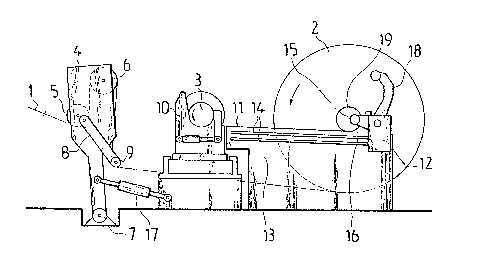
Figure 1 shows a partially diagrammatic side view of a
continuously running rewinder in accordance with the invention
before severing the web and splicing with a fresh roll.
Figure 2 shows the rewinder of Figure 1 in a partially
phantom top view for the coupling of the rewinder secondary
drive to the reel-up drum.
The rewinder in accordance with Figure 1 operates as follows:
When a rewinding reel-up drum 2, 3 is supported by roll
stands 10, rotated by the primary drive and is attaining
the full roll diameter presupposing a changeover, a movable
secondary drive l5 mounted on a transfer carriage l2, is
connected to the reel-up drum 2. A pressure roller assembly 4
pivotable at a point 7 on a base is released, actuated
by a hydraulic cylinder 17, and a bar-shaped pressing shaft
8, 9 pivoted on it forces a web 1 down. A transfer device
11...14 transfers the full reel-up drum 2, which is rotated
by the secondary drive 15, off from the roll stands 10
to an exit point 16. Then a lift transfers a new, empty
reel-up roll 3 onto the roll stands 10.
Tne primary drive of the rewinder synchronizes tlle rotation
speed of the new reel-up drum 3 witll the web speed. This
phase is shown in Figure 1. The pressiny bar 8 rises up
and the pressure roller assembly 4 is closed swingin~ toward
the roll stands 10. A knife bar (not shown), located before
the pressure roller assembly 4, severs a longitudinaL cut
at a distance of about 150 mm from the edge of the web 1.
A compressed air jet in the roll stand 10 forces this strip

3~355
over the fresh reel-up drum 3.
Then, the knife bar moves transversely over the entire
web 1, forcing the web 1 to be totally engaged on the new
reel-up drum 3. The completed roll on the reel-up drum 2
is stopped and it remains waiting for removal.
The construction of the pressure roller assembly 4 is of
standard prior art type, except for a pressing bar ~, 9,
pivoted on it and actuated by hydraulic cylinders (not
shown). ~Jhen lifted to the upper position, the shaft part 9
of the pressing bar forms a jaw safety device in front of
the nip between the pressure roller 6 and the reel-up roll 3,
disposing with a separate jaw safety device. The roll stands
10 are of standard prior art construction incorporating
swinging and longitudinal transfer facilities at tlle service
side.
The transfer device of the reel-up drum 2, 3 comprises rolling
rails 11, transfer carriages 12, and th~ secondary drive 15.
The reel-up drum 2 is rolled downwards along a gently sloping
track, guided by transfer carriages 12. The transfer carriages
l2 are mounted to a frame 13 of the rolling rails 11 by
ball-bushing guides 14. The carriages 12 are moved by
ball-nut lead screws mounted on both rails 11. The ball-nut
lead screw movements are synchronized mechanically by a
connection shaft and they are rotated by a common drive
motor. The secondary drive is a hydraulic motor 15, which
is mounted on the transfer carriage 12 of the service side.
In accordance with Figure 2, the shaft of the hydraulic
motor 15 carries a small gear wheel 21 that drives directly
the inner ring 20 of the the toothed coupling of a reel-up
drum shaft 19, thus forming an inside driven gear with
3~ it. This configuration provides a reduction gear, disposing
with a separate reduction gear for the hydraulic motor l5.

Dessin représentatif
Une figure unique qui représente un dessin illustrant l'invention.
États administratifs

2024-08-01 : Dans le cadre de la transition vers les Brevets de nouvelle génération (BNG), la base de données sur les brevets canadiens (BDBC) contient désormais un Historique d'événement plus détaillé, qui reproduit le Journal des événements de notre nouvelle solution interne.

Veuillez noter que les événements débutant par « Inactive : » se réfèrent à des événements qui ne sont plus utilisés dans notre nouvelle solution interne.

Pour une meilleure compréhension de l'état de la demande ou brevet qui figure sur cette page, la rubrique Mise en garde , et les descriptions de Brevet , Historique d'événement , Taxes périodiques et Historique des paiements devraient être consultées.

Historique d'événement

Description Date
Le délai pour l'annulation est expiré 2000-12-12
Lettre envoyée 1999-12-13
Accordé par délivrance 1989-12-12

Historique d'abandonnement

Il n'y a pas d'historique d'abandonnement

Historique des taxes

Type de taxes Anniversaire Échéance Date payée
TM (catégorie 1, 8e anniv.) - générale 1997-12-12 1997-11-03
TM (catégorie 1, 9e anniv.) - générale 1998-12-14 1998-11-19
Titulaires au dossier

Les titulaires actuels et antérieures au dossier sont affichés en ordre alphabétique.

Titulaires actuels au dossier
VALMET PAPER MACHINERY INC.
Titulaires antérieures au dossier
ARI BJORKMAN
ARI LASSILA
HARRI KUOSA
PEKKA HAAPANEN
RAUNO HAGEL
Les propriétaires antérieurs qui ne figurent pas dans la liste des « Propriétaires au dossier » apparaîtront dans d'autres documents au dossier.
Documents

Pour visionner les fichiers sélectionnés, entrer le code reCAPTCHA :


Pour visualiser une image, cliquer sur un lien dans la colonne description du document. Pour télécharger l'image (les images), cliquer l'une ou plusieurs cases à cocher dans la première colonne et ensuite cliquer sur le bouton "Télécharger sélection en format PDF (archive Zip)" ou le bouton "Télécharger sélection (en un fichier PDF fusionné)".

Liste des documents de brevet publiés et non publiés sur la BDBC .

Si vous avez des difficultés à accéder au contenu, veuillez communiquer avec le Centre de services à la clientèle au 1-866-997-1936, ou envoyer un courriel au Centre de service à la clientèle de l'OPIC.


Description du
Document 
Date
(aaaa-mm-jj) 
Nombre de pages   Taille de l'image (Ko) 
Revendications 1993-09-14 2 68
Abrégé 1993-09-14 1 36
Dessins 1993-09-14 1 25
Description 1993-09-14 4 147
Dessin représentatif 2001-09-30 1 14
Avis concernant la taxe de maintien 2000-01-09 1 178
Taxes 1996-11-03 1 69
Taxes 1995-11-08 1 57
Taxes 1994-11-16 1 60
Taxes 1992-11-26 1 45
Taxes 1993-10-24 1 43
Taxes 1991-11-20 1 53