Note : Les descriptions sont présentées dans la langue officielle dans laquelle elles ont été soumises.
126~21 ~
72166-2
The present invention relates to a connecting device for
a wiper system which comprises an actuating arm, at the front end
of which is rotatably attached a wiper blade by means of a first
element, and which comprises a control arm of which the front end
is also rotatably attached to said first element by means of a
second element.
In the prior art such wiper systems are known as being
pantograph systems or, more commonly, as being pantograph arms.
United States patent 3,893,204 may be cited as an example of a
prior art pantograph arm. In that patent the first element is
represented by the reference numeral 20 and is, on one side,
attached to the actuated arm by a first rivet and, on the other
side, attached to the control arm by a second rivet. Said elemen-t
20 may rotate or swivel about the axes formed by said two rivets,
which are substantially perpendicular to the surface to be wiped.
Concerning the same United States patent it is to be
noted that the control arm is attached to its driving mechanism in
such a way that it may rotate or swivel about two axes which are
substantially perpendicular one with respect to the other and of
which one is substantially perpendicular to the surface to be
wiped.
In said United States patent 3,893,204 and in the
present invention said first element thus may rotate or swivel
with respect to the control arm. Since said first element is
moreover attached by conventional means to the superstructure of
the wiper blade, the wiper blade may, under the action of the
~;~42~
actuating arm, rotate or swivel with respect to the actuating arm
about an axis which is substantially perpendicular to the surface
to be wiped. This system, i.e. pantograph arms in general,
permits an increase of the surface to be wiped by the wiper
blade.
It is a known fact ~ha~ the rivet connection between the
control ar~ and said first element is a very unsatisfactory solu-
tion. Indeed the rivet and said first element are subject to
torsion forces with each oscillating movement of the actuating arm
and of the wiper blade, 2 torsion forces which are due to the
curvature of the surface to be wiped, i.e. generally the wind-
shield of a motor vehicle. As a consequence, said rivet connec-
tion is subject to rapid wear and the wiping quality will diminish
with time.
In some know pantograph wiper arms the rivet which links
the control arm to said first element has been replaced by a ball-
joint which, apparently,eliminates the above mentioned disadvan-
tage. In fact even a ball-joint is subject to wear and said wear
is not negligible if the ball-joint has not been carefully
designed, in particular as to the materials used. Thus, special
materials must be used and the ball-joint becomes rather complex
and, consequently, relatively expensive.
It is to be noted that the two substantially perpendicu-
lar axes by which the control arm of the United States
patent 3,893,204 is linked to its driving mechanism have also been
replaced in some Xnown pantograph arms by a ball-joint. The
remarks made in the preceding paragraph also apply to such a
ball-joint.
-- 2
The first object of the invention is to provide a panto-
graph wiper arm - and more particularly a connecting device
between the con-trol arm and said first element - which eliminates
the above mentioned disadvantages of the known pantograph arms.
A second object of the invention is to simplify and to
diminish the costs of the articulation or articulations between
the con-trol arm of a pantograph system and its driving mechanism.
The connecting device according to the invention is
substantially characterized by the fact that said second element
is made of a flexihle material, that it has an elongate form and
that in its central portion it has a substantially circular cross-
section.
Preferably, said second element is made of an elastomer,
such as a polyester elastomer.
The rear end of the control arm may be attached to its
driving mechanism by means of an element which is identical with
said second element.
Other characteristics of the invention will be better
understood when reading the following description of two embodi-
ments in con~unction with -the appended drawings, wherein:
Figure 1 is a top view of the front end of a pantograph
arm according to the first embodiment of the invention,
Figure 2 i5 a section, along line II-II, of the panto-
graph arm of Figure 1,
Figure 3 is a section, along line III-III and turned
counter-clockwise by 90, of the pantograph arm of Figure 1,
6~
Figure ~ is a section, along line IV-IV, of the panto-
graph arm of Figure 1,
Figure 5 is a -top view of said first element according
to the first embodiment of the invention,
Figure 6 i9 a side elevational view, along arrow VI and
turned clockwise by 90, of the element represented in Figure 5,
Figure 7 is a section along line VII-VII of Figure 5,
Figure 8 is a section along line VIII-VIII of Figure 6,
Figure 9 is, to a larger scale, a top view of said
second element according to the first embodiment of the inven-
tion,
Figure 10 is a side elevational view, along arrow X, of
the element represented in Figure 9,
Figure 11 is an axial section of the element represented
in Figure 9 and Figure 10,
Figure 12 is a section, along line XII-XII, of the
element represented on Figure 11,
Figure 13 is a top view of the front end o-f a pantograph
arm according to the second embodiment of the invention,
Figure 14 is a section, along line XIV-XIV, of the
pantograph arm of Figure 13,
Figure 15 represents, in section, one of the elements of
Figure 14,
Figure 16 is a right hand end view of the element repre-
sented in Figure 17,
~LZ~
Figure 17 is, to a larger scale, a top view of said
second element according to the second embodiment of the inven-
tion,
Figure 18 is a left side view, in the direction of arrow
XVIII, of the element represented in Figure 17,
Figure 19 is a section along line XIX-XIX of Figure 17,
Figure 20 is a section along line Xx XX of Figure 17,
Figure 21 is a section along line XXI-XXI of Figure 17,
Figure 22 is a top view of an element of the driving
mechanism of the pantograph arm according to -the invention,
Figure 23 is a side elevational view, along arrow XXIII
of Figure 22,
Figure 24 is a section along line XXIV-XXIV of
Figure 22,
Figure 25 is a side elevational view, to a larger scale,
of the connecting element between said second element and the
driving mechanism of the control arm of the pantograph system
according to the invention,
Figure 26 is a side elevational view, along arrow XXVI,
of the element represented in Figure 25,
Figure 27 is a top view of the element represented in
Figure 25,
Figure 28 is a section along line XXVIII-XXVIII of
Figure 27.
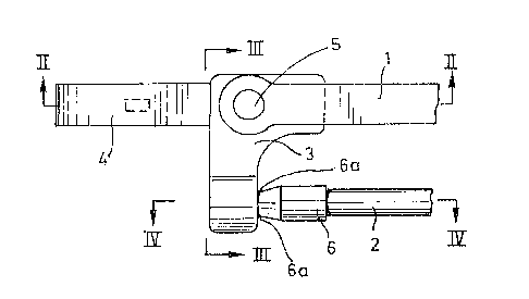
The front end of the pantograph arm according to the
first embodiment of the invention (Figure 1 through 12) comprises:
an actuating arm 1, a control arm 2, a first intermediate element
~26~9~2~L
3 between the two arms 1, 2, a second intermediate element 6
between the two arms 1, 2, a hook 4 and a rivet 5.
The wiper blade (no-t shown) is attached to the hook 4 by
means of an appropriale connector and can rotate, or swivel, about
the pivot formed by the rivet 5, under the action of the control
arm ~ and via the intermediate elements 6 and 3. It is to be
noted that when the actuating arm is working (oscillating move
ment) the control arm 2 is actuated by a driving mechanism which
is known in the prior art and which is part of the driving
mechanism of the actuating arm 1.
In Figures 2, 7 and 8 it can be seen that the rear end
of the hook 4 is inserted into a cavity 3c of the element 3, a
cavity which has slightly larger dimensions than said rear end of
the hook 4. It is the rivet 5 (Figure 2) which retains the rear
end of the hook 4 in the cavity 3c of the element 3.
Said first element 3 (Figure 5 through 8) is made of a
relatively rigid plastic material and has substantially the
general form of an L of which one of the legs is provided with the
cavity 3c for receiving the rear end of the hook 4 and of which
the other leg is provided with the cavity 3a into which is
inserted the front end 6' (Figure 9) of said second element 6
which in turn is attached to the front end of the control arm 2.
In Figures 5, 7 and 8 it can be seen that in the element
3 a cylindrical opening 3b is provided for inserting therein the
rivet 5 about which said element 3, and consequently the hook 4,
may rotate or swivel between the limits imposed on it by the
control arm 2.
lZ~i91 2~
In the first embodiment of the invention (Figures 1
throuqh 12) the control arm 2 has the form of a cylindrical bar
and, in a first approximation, it can be said that said second
element 6, which links the control arm 2 to the element 3, has
also the general form of a cylinder. The cylindrical form of the
element 6 is however not essentialO Indeed its form can also be
any other elonga-t~ form.
The element 6 is the most important element of the
invention and constitutes in fact the connecting device according
to the invention, i.e. it embodies the connection between the
control arm 2 and the element 3. As already said above, the front
end 6' (Figure 9) of the element 6 is inserted into the cavity 3a
of the element 3 and can, for example, be cemented therein. It is
however to be noted that any other retention system can be used
and, in particular, any snap-on system.
The front end of the control arm 2 is inserted into the
cavity 6b of the rear end 6"' of said element 6 and is retained in
said cavity in the same manner as is retained the front end 6' of
the element 6 in the cavity 3a of the element 3, including any
snap-on system.
Figure 9 and Figure 11 show that the central portion 6"
of the element 6 has a reduced cross-section (6a) with respect to
the front (6') and rear (6'") ends of said element 6. Figure 12
shows moreover that said reduced cross-section 6a has a circular
form. The element 6 being, according to the invention, made of an
elastomer, and preferably of a polyester elastomer, it can be
easily seen that said central portion 6", or the reduced cross-
1; :64;Z ~1.1
section 6a, can not only act as a pivot, but also as a ball-joint,
i.e. that the control arm 2 may take different angular positions
with respect to the elemen-t 3 and this in all directions.
The last-mentioned feature is important since the
torsion forces mentioned above are absorbed by the element 6 with-
out producing the inevitable wear of parts in the pantograph
systems known in the prior art. Moreover, a simple elastomer
element replaces a relatively complex ball-joint. A non-
negligible reduction of costs is thus obtained.
In the case of the thus described first embodiment of
the invention Figure 4 and Figure 8 show schematically that the
angular movements of the control arm 2 may be limited by a
widening 3a' (towards the control arm) of the cavity 3a of the
element 3.
Just as for the first embodiment, the front end of the
pantograph arm according to the second embodiment (Figures 13
through 21) comprises: an actuating arm 1, a control arm 12, a
first intermediate element 13 between the two arms 1, 12, a second
intermediate element 16 between the two arms 1, 12, a hook 4 and a
rivet 5.
The connections between the actuating arm 1, the rivet
5, the first intermediate element 13 and the hook 4 are realized
in exactly the same manner as in Figure 1, i.e. as in the first
embodiment of the invention. The same is true as to the relative
movements of these different elements one with respect to the
other when the pantograph arm is working.
Just as before, said first element 13 (Figures 13, 14
and 15) is made of a relatively rigid plastic material and has
~Z~21~
substantially the form of an L of which one of the legs is pro-
vided with a cavity for receiving the rear end of the hook 4 and
of which the other leg is provided with the opening 13a into which
is inserted the front end 16' (Figures 17 and 20) of said second
element 16 which in turn is attached to the front end of the
control arm 12.
Ln the present case -the control arm 12 has a substan-
tially rectangular cross section and the form of the rear end 16"'
(Figures 17 and 20) of the element 16 has been modified accor~
dingly. Just as in the first embodiment, the front end of the
control arm 12 is inserted into the cavity 16b (Figures 16 and 20)
of the element 16 or is attached to said element 16 in any other
way, including by means of a snap-on system.
The front end 16' (Figure 20) of the element is inserted
into the opening 13a (Figure 15) of the element 13 and is retained
therein by means of a snap-on system which comprises (a) in the
opening 13b: an annular shoulder 13c and (b) on the front end 16'
of the element 16: a corresponding annular recess 16d.
The central portion 16" of the element 16 has a reduced
circularly shaped cross-section 16a, just as in the first embodi-
ment, and thus can function in the same manner as a ball-joint,
with the advantages mentioned above, advantages which are essen-
tially due to the fact that the element 16 is made of an elastomer
and preferably of a polyester elastomer.
Just as before the angular movements of the control arm
12 may be limited by a widening 13a' (towards the control arm) of
the opening 13a of the element 13. The snapping of the front end
16' of the element 16 into the opening 13a of the element 13 may
~Z69~Zl~
be facilitated by providing said front portion 16' with a cavi~y
16c (Figure 18 and 20). Once the fron~ end 16' of the element 16
has snapped into the opening 13a of the element 13, a stud of
appropriate dimensions may be inserted into said cavity 16c, thus
avoiding any accidental dislocation of the element 16.
Figures 22 through 24 schematically represent the
driving mechanism of the control arm 2, 12. This mechanism is
actuated by the drive shaft of the actuating arm 1, which drive
shaft is represented in Figure 22 and Figure 24 by its geometrical
axis A-B. The element 8 has a circular opening 9 through which
passes the drive shaft of the actuating arm 1 and consequently of
the control arm 2, 12. Eccentrically with respect to the axis A-B
the element 8 is provided with a stud 10 which is perpendicular to
the element 8. It is to this stud 10 that the rear end of the
control arm 2, 12 will be attached by articulation means.
To this effect the element 23, represented in Figures 25
through 28, will be placed onto said stud or, in other words, the
stud 10 will be inserted into the cavity 23b of the lower portion
23" of said element 23 and will, for example, be cemented there-
in.
The upper portion of the element 23 is provided with acavity 23a which has the same dimensions as the cavity 3a of the
element 3 (Figure 8) of the first embodiment of the invention and
the articulation between the con~rol arm 2 and the element 23 will
be realized by an element which is identical with the element 6
(Figures 9 through 12) of the first embodiment of the invention.
In other words, the rear portion 6"' of the element 6 is attached
- 10 -
~Z64~
to the rear end of the control arm 2 and the front end 6' of the
element 6 is inserted into -the cavity 23a of the element 23.
Between the rear end of the control arm 2 and the
element 23 the element 6 will thus have the same function as in
the first embodiment of the inven-tion, i.e. it will function in
the same manner as a ball-joint. It is moreover quite evident
that the element 6 and the elemen-t 23 may be designed in such a
way that they are linked together by means of a snap-on system
similar to that of Figures 14 through 21.
Two advantageous embodiments of the invention have thus
been described. In taking into consideration the fact that one
single element ~6, 16) may be used at the front as well as at the
rear end of the control arm 2, 12, for replacing ball-joints, it
is easy to appreciate not only the simplicity of the proposed
solution, but also the lower costs made possible by said solu-
tion.
- -- 11 --