Note : Les descriptions sont présentées dans la langue officielle dans laquelle elles ont été soumises.
3Ç~
OPTICAL TEMPERATURE MEASUREMENT TECHNIQUES
.
Background of the Invention
This invention relates generally to the art of
optical temperature measurements, and more particularly
to those made with the use of luminescent materials that
emit radiation having a measurable characteristic that
varies as a function of temperature.
T'nere are many temperature measurement appli-
cations suggested for optical techniques using lumi-
nescent materials as the temperature sensor. One is aremote, non-contact method of measuring temperatures by
coating a surface of interest with a luminescent
material, exciting the material to luminesce by directing
e~citation radiation against it, and directing the
resultant temperature dependent luminescent radiation
onto a detector by an appropriate optical system such as
one using lenses or optical fibers. Applications of the
non-contact technique include accurate measurements of
surface temperature, including surfaces of objects posi-
tioned within a vacuum chamber, measurement of thetemperature of movins materials or machinery, and mea-
~,, ~
surements of the temperature distribution over largesurface areas which would be difficult or impractical to
instrument with contact type point sensors. Other appli-
cations include those where the luminescent sensor
material is contained in a structure designed to slip over
but not be permanently attached to an optical fiber or
fiber bundle. This can be either as a disposable item oe
as a special configuration for use in measuring high
temperatures.
Another method of application of optical tech-
niques includes the formation of a temperature sensing
probe by attaching a small amount of luminescent material
to an end of an optical fiber or bundle of fibers, and then
immersing the probe in an environment whose temperature
is to be measured. Applications of the probe technique
include those in medical hyperthermia, a cancer therapy
treatment wherein the small probe is implanted in a human
body to measure internal temperatures during induced
heating, and in measuring internal temperatures of large
electrical machinery such as power transformers. The
measurement is made by an instrument remote from the
sensor to which the other end of the fiber or fiber bundle
is connected. The instrument generates excitation
radiation which is passed to the sensor through the fiber,
and then receives the luminescent radiation from the
sensor for detection and measurement of the temperature
of the sensor. Commercial instruments exist that use
this optical fiber probe technique. A particular advan-
tage of the optical fiber probe over standard thermo-
couple or other electrical temperature sensing devices,is that it is not affected by electromagnetic energy
fields since the probes contain no electrically con-
ducting materials. The fact that the technique is
d .~
optical rather than electrical also allows applications
where the light path from a luminescent materiai sensor to
an instrument can include segments containing only
vacuum, air, liquid or other material transparent in the
spectral region of interest.
There are two basic .ypes of luminescent
radiation detection techniques now being used or sug-
gested for use for such temperature measurements. One of
the techniques is to measure the static intensity of the
luminescent radiation to determine the temperature of the
luminescent material. The other technique is to modulate
the excitation of the luminescent material and then
measure the time dependent characteristics of the lumi-
nescence as a function of temperature.
It was early recognized that the luminescent
intensity technique had inherent errors in its readings
due to variations in the luminescent intensity caused by
factors other than the temperature of the luminescent
material. One factor, for e~ample, is a change of
intensity of the excitation radiation source over time,
which causes a corresponding change in the luminescent
intensity that is unrelated to temperature. Another
factor is a change in intensity of radiation transmitted
by an optical fiber when the fiber is bent. In order to
eliminate such changing intensity and similar non-
temperature related factors from affecting the resulting
temperature reading, commercial instruments utilize, and
the literature suggests, examining the intensity of the
luminescence at two separate definable wavelength bands
emanating from the same sensor. Signals proportional to
those separate intensities are then ratioed or otherwise
con,pared in order to eliminate such non-thermal intensity
changes which are common to both signals. The intensity
3i~
ratioing technique has been very useful for improving
accuracy of temperature readings bu-t has been found not to
eliminate all causes of intensity variations caused by
factors other than temperature change of the sensor.
Errors caused by these other factors can be reduced
further by re-calibration of the temperature sensor
wherein the sensor is held at a known temperature and the
instrument then adjusted to read that temperature.
Time dependent temperature measurements sug-
gested in the literature, the second of the two basic
types of luminescent techniques, are generaily insensi-
tive to these other factors since relative intensities
are not measured. These techniques measure the tempera-
ture dependent characteristics of luminescent decay that
continues after the excitation radiation has ceasedO
~owever, these techniques have a disadvantage of not
being repeatable under all circumstances and thus also
require recalibration of the temperature sensor during
use.
Frequent calibration is difficult or undesir-
able in many applications, such as in non-contact surface
temperature measurements, production and/or process con-
trol applications, measurements requiring an optical
fiber probe to be permanently installed in a large piece
of operating equipment, measurements during a medical
procedure, or with the use of sterile disposable optical
fiber temperature probes that would require calibration
before use of each new probe.
Therefore, it is a primary object of the
present invention to provide an improved optical tempera-
ture measurement technique that requires either no or
only one time calibration.
It is another object of the present invention
36
to provide a technique that is useful for having its
temperature probes permanently installed in electrical
machinery.
It is a further object of the present invention
to provide a technique that is useful with disposable
temperature sensing probes or sensors.
It is yet another object of the present
invention to provide a technique that is useful for
measuring remotely the temperature of surfaces.
It is still another object of the present
invention to provide a technique that is useful for
measuring the temperature of rotating or moving objects
without contact with them.
It is another object of the present invention
to provide a luminescent temperature measuring technique
that works well at high temperatures, thereby to be more
useful in industrial and process control applications.
Summary of the Invention
These and additional objects are accomplished
by the present invention, wherein, briefly, the
characteristics of a luminescent material and luminescent
detection techniques are optimized. ~ time dependent
type of optical temperature measurement technique is
utilized. The luminescent material is chosen to have a
highly reproducible luminescent intensity function con-
tinuing in time after termination of the excitation
radiation that closely approximates a single expo-
nentially decaying function whose time constant is
related unambiguously to temperature, and which is
substantially independent of the excitation radiation
intensity, the effect of binding or dispersing media, and
any prior temperature or excitation history of the
luminescent material. It has been found that the use of
such a luminescent material as a temperature sensor in a
decay time measuring system overcomes the difficulties of
the intensity ratioing type of system described above, as
well as the errors introduced by the use of other types of
luminescent sensors in a time dependent measurement
system. One example of such a luminescent material is
either magnesium germanate or magnesium fluorogermanate,
activated with tetravalent manganeseO A preferred form
of the luminescent sensor is a powder comprising a very
large number of small particles or crystallites having
similar composition and properties. This form allows the
coating of surfaces of various shapes and sizes using a
binder or adhesive of appropriate characteristics. This
form also minimizes the problem of controlling differ-
ences in decay time characteristics from crystallite to
crystallite since the signal is the sum of those from each
of a large number of such crystallites. A preferred
measurement system detects the luminescence decay time
directly over a portion of the decaying intensity curve at
the same specific time after the excitation pulse.
The use oE such a sensor material and measuring
system allows the making of accurate and repeatable
temperature measurements with very little or no cali-
bration being necessary. One class of applications wherethis is important is those where the luminescent radia
tion imaging system includes the possibility of dimen-
sional changes over time or between different sensors.
For example, in the measurement of surface temperatures,
the luminescent material is coated or otherwise attached
to the surface whose temperature is to be measured and is
optically coupled to an instrument without physical
contact with the luminescent material, by lenses or by an
36
optical fiber. The specific positioning of the optical
elements with respect to the sensor is likely to change
during a particular measurement and will undoubtedly be
different from measurement to measurement. Other exam-
ples of applications involving variable optical dimen-
sions or geometrics include the use of probe covers
attached to optical fibers and optical commutation
between a sensor on a moving part and a stationary
measuring instrument. Provided sufficient optical
signals are generated, the technique of the present
invention is insensitive to such dimensional or geometric
variations and further does not require the frequen~
calibration of prior techniques tha~ is so extremely
difficult in such applications.
The use of such a sensor material and measuring
technique also allows the fabrication of an optical fiber
probe which can be permanently implanted in a large piece
of machinery or equipment and left there since no periodic
calibration is required.
This luminescent ma~erial also makes practical
the use of disposable optical fiber probes, particularl~
useful in medical applications, since calibration of each
new sensor is not required and since the effects of fiber
bending will not affect the accuracy of the sensors.
Additional objects, features and advantages of
the various aspects of the present invention will become
apparent from the following description of its preferred
embodiments, which description should be taken in con-
junction with the accompanying drawings.
Brief Description of the Drawings
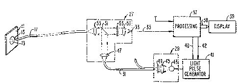
Figure 1 schematically illustrates an improved
optical temperature measurement system according to the
~;~fi~
present invention;
Figure 2 shows waveforms occurring in the
system of Figure 1 in operation;
~ igure 3 is a curve illustrating, as an
example, the characteristics of the sensor of Figure 1
with a particular luminescent material;
Figure 4 is a block diagram of an électronic
processing circuit for the system of Figure l;
Figure 5 is a timing diagram showing the
operation of the circuit of Figure 4;
Figures 6 and 7 show examples of one alternate
form of a temperature sensor;
Figures 8 and 9 illustrate other forms of a
temperature sensor;
Figure 10 schematically illustrates an appli-
cation of the techniques of the present invention
utilizing an optical fiber probe.
Description of the Preferred Embodiments
An example of a particular application for
optical temperature measurement is illustrated in Figure
1. In that example, the temperature of a surface 11 is
measured. The surface 11 could be part of, for example,
an integrated circuit wafer whose temperature is to be
monitored during processing, a component of a large piece
of machinery, a model aircraft in wind tunnel tests, and
many others. Measurement of surface temperature, even
for stationary objects, is extremely difficult since heat
flow between the surface and any contact type sensor will
typically be dominated by flow from other sources, with
performance being a very strong function of the thermal
contact between the sensor and the surface. Even infra-
red techniques are imprecise because the infra-red
~L~6~3,6
emissivity of the surface must be accurately known and
interferences from reflections from other infra-red
sources must be eliminated to allow correct conversion of
measured infra-red radiation to true surface temperature.
To overcome these problems, a layer 13 of
luminescen~ ~aterial is attached to the surface 11. This
attachment can be accomplished in many ways, such as by
coating the luminescent material suspended in powder form
in a binder of resin or glass directly onto the surface.
An appropriate glass binder is potassium silicate or
Corning*sealing glass. An appropriate resin is silicone
hard coating material. Alternatively, a substrate
carrying the luminescent material, as illustrated in
Figures 6 and 7, may be attachea to the surface 11, as
lS another specific example. In either case, the coating of
luminescent material comes into thermal equilibrium with
the surface 11 whose temperature is to be measured.
The luminescent temperature sensor 13 is ex-
cited to luminesce upon illumination with visible or near
visible light emitted from the end 15 of an optical fiber
communication medium 17. Alternatively, excitation
radiation could be directed against the sensor 13 by
optical elements independent of the optical fiber 17,
such as by flooding the sensor with such radiation. The
wavelength range of the excitation radiation is appro-
priate for the particular luminescent material 13 being
utilized. The optical fiber medium end 15 is held a
distance away from the sensor 13 without contact between
them. The resultant luminescent radiation, in a visible
or near visible radiation band is usually, but not
necessarily, of longer wavelength than the excitation
radia~ion. The luminescence is captured by the end lS of
the optical fiber communication medium 17 and passed
* Trade Mark
~,
~, i
~2g~L~ 316
therealong to the measuring instrument. The fiber medium
17 can include a single fiber, a number of fibers, or an
auxilliary light collecting lens or mirror system,
depending upon the particular applica~ion.
It is a temperature dependent characteristic of
the luminescent radiation from the sensor 13 that is
measured in order to determine temperature of the
luminescent material and thus of the surface 11. One
such characteristic used in existing instruments is the
relative intensity in two fairly narrow wavelength bands.
But it has been found that the use of an optical fiber
system can cause reading errors because of the charac-
teristics of the fiber system itself. These sources of
error are due to the unequal transmission of the two
wavelength bands of radiation that are measured. A
change in such relative transmission differences results
from bending of the fiber medium itself. The light
radiation is passed through the fiber by repetitive
reflections at the interface between the fiber core and
its cladding. Light striking its interface at less than
a critical angle determined by the indices of refraction
of the fiber core and cladding, is totally internally
reflected and hence trapped in the fiber to be transmitted
down its length by repeated reflection. However, the
indices of refraction vary with wavelength.
Therefore, the ratio of transmitted inten-
sities is a function of the two wavelengths of interest.
By calibrating the two wavelength ratioing system against
a known temperature~ this transmission difference can be
corrected. However, bending the fiber will cause the
critical angle for total internal reflection to change
differently for the two wavelengths. The result will be
a change in the ratio of the two transmitted intensities.
?~36
This is interpreted as a change in the temperature reading
which is, of course, undesirable because the change has
nothing to do with the actual temperature of the sensor 13
that is to be measured.
The bending effect is particularly important in
medical applications where high accuracy is required and
where fiber bend~ng may be unavoidable in clinical use.
There are also many other effects which can change the
ratio in the two-wavelength system over longer periods of
time which may be more important in various industrial
applications. For example, if the transmission link is
an optical fiber and if there is high energy radiation
present, as in a nuclear reactor, color centers may be
formed in the fiber over a period of time which change its
spectral transmission characteristics and hence the
relative transmission at the two wavelengths of interest.
In such an application, because of the radiation levels,
it would be difficult to recalibrate frequently. It is
also possible that the electronic gain of the two
detectors and signal processing channels might change
with time or temperature. In all cases, such relative
changes in the two separate channels of the ratioing
system will produce apparent temperature changes which
are not valid.
These non-temperature dependent factors that
affect the temperature reading may not be a serious
problem in some applications, particularly if the mea-
surement time after calibration is short, if the tempera-
ture accuracy required for the application is not high, or
if it is practical to correct the errors by periodic
recalibration over time. But in applications where
accuracy must be high, or where recalibration is not
practical, these factors must be taken into account. The
12
two intensity ratioing technique inherently eliminates
many potentially erroneous non-temperature variations
that would affect the temperature reading, but as noted
above, does not automatically cancel all signal varia-
tions that may occur over time in the two separatechannels. Some of these undesirable variations may be
kept under control by recalibration of the system from
time to time but this requires placing the luminescent
sensor of the system at a known temperature so that
instrument adjustments can be made. This calibration
requirement is inconvenient in any case where it is
required to be done very often, and may be impractical in
many desired temperature measurement applications where
the sensor is fixed at a remote and inaccessible location.
For example, in the surface temperature mea-
surement technique illustrated in Figure 1, it may be very
difficult or impossible to measure independently the
temperature of the surface 11 at the position of the
sensor 13 in order to make this calibration. And once the
calibration is made, any bending of the fiber medium 17 or
any long term change in the relative gain of the two
signal processing channels would introduce errors that
would require recalibration.
Therefore, in order to eliminate these dis-
advantages, the system of Figure 1 excites the phosphor 13
with a pulse of light, and then after the pulse has ended,
measures a specific characteristic of the decaying
luminescent intensity such as its decay ~ime. With this
technique, only one wavelength band is required. This
could use the entire emission band of the luminescent
material, or a narrower band selected from the total
emission. In any event, only one optical path and one
spectral band is involved for the returning signal and
236
13
only one detector and one signal processing channel is
used for each sensor to detect and analyze the transient
data. ~s a result, all of the errors associated with the
two channel system mentioned above disappear. The only
surviving re~uirements are: (1) that the decay time is
trul~ characteristic of the sensor material and is not
affected by either the intensity of excitation (within
bounds) or the thermal or illumination history of the
sensor, and (2) that there are no extraneous time
dependent signal changes, as from stray light, which
occur during the brief interval of the measurement and
which alter the detected temperature signal.
Returning to Figure 1, an optical system 27
connects the fiber medium 17 with a source 29 of
excitation radiation through another fiber medium 31.
The optical assembly 27 also communicates the luminescent
radiation from the fiber medium 17 to a detector 33 that
is electrically connected by conductors 35 to an elec-
tronic processing system 37. The processing circuits 37
convert, by reference to an empirically established
conversion table, the luminescent radiation decay charac-
teristics of the sensor 13 into a temperature that is
indicated at a display 39. The timing of an excitation
pulse driving circuit 41 is controlled by the processing
circuits 37 through a line 40. The circuit 41 is
connected to a flash lamp 43 of the excitation source 29.
Its brightness is set by a signal in line 42. The
periodic pulse from the lamp 43 is imaged by a lens 45
through a bandpass filter 49 into an end of the optical
fiber transmission medium 31. The filter 49 limits the
wavelengths to the range that is useful to excite the
particular luminescent sensor 13. As indicated in Figure
1, the processing circuits 37 and excitation source 29 can
~~2~ 6
14
be shared among a number of temperature sensors by
repeating the optical system 27 for each.
The optical system 27 includes a lens 47 for
collimating the excitation light at an end of the fiber
medium 31. I'he collimated excitation pulses are directed
to a beam splitter 51 and thence through a lens 53 into an
end of the optical fiber transmission medium 17 for
excitin~ the sensor 13 to luminescence.
As an alternative technique for providing
excitation radiation, the source 29 and pulse generator
41 could be replaced by a continuous source, such as a
tungsten lamp, a light emitting diode or a laser, with a
mechanical chopper positioned to interrupt the emitted
light in synchronism with the decay time measurements and
controlled by the processing circuits 37. As another
alternative, the beam splitter could be eliminated with
instead one or more fibers conducting exciting radiation
from the source to the sensor and another one or more
fibers conducting the emitted luminescence from the
sensor to the detector.
The luminescent radiation from the sensor 13 is
returned by the fiber medium 17 to the instrument where
the returning radiation is again collimated by the lens
53. The collimated beam passes through the beam splitter
51 and an optical filter 55 which limits the radiation
passing through it to the wavelength band of luminescence
of the sensor 13. The wavelength bands allowed to pass by
the filters 49 and 55 will ideally be non-overlapping. A
lens 57 focuses the filtered luminescent radiation onto
the detector 33 which may be a photodiode that is
sensitive to the range of wavelengths passing through the
filter 55.
As an alternative to the use of only an optical
~4;~3~i
fiber system 17 as the light communication medium between
the sensor 13 and the optical system 27, other optical
elements, such as lenses, can be used either in combi-
nation with or in place of optic:al fibers.
Operation of the system of Figure 1 is ex~
plained with additional reference to the waveforms of
Figure 2. Figure 2(A) shows periodically .epetitive
excitation light pulses 61 and 63. The resultant lumi-
nescent radiation of the sensor 13 when so excited is
shown in Figure 2(B). During the existence of the
excitation pulse 61, for example, between times t0 and tl,
the luminescent intensity rises as shown by the curve
portion 65. But at time tl when the pulse 61 ends, the
luminescence continues for a time, as indicated by curve
portion 67. It is the rate of decay of the curve portion
67 that is measured by the processing circuits 37 as an
indication of temperature. By the time t4, the lumi-
nescence has substantially ended. The next pulse may
occur at any time after that, as indicated by the pulse
63. A single luminescence decay measurement is all that
is necessary to determine temperature, but repeating the
process allows monitoring changes in temperature and also
provides a number of independent readings over a short
period of time that may be averaged by the processing
circuits 37, if desired, to provide higher precision
readings.
A preferred luminescent material for the sensor
13 whose luminescent decay time is being measured has
several desirable characteristics. A first is that the
decay characteristics be repeatable. That is, the rate
of decay and shape of the decay curve 67 of Figure 2(B~
should be the same for repetitive measurements of a single
temperature of the sensor 13. It should be independent
~6~;Z 36
16
of the intensity of the excitation radiation, both of the
radiation which causes the particular luminescence decay
that is being measured and of excitation radiation that
has been directed against the sensor in prior measure-
ments. The decay curve 67 should also be independent ofany prior temperatures to which the sensor has been
driven. The material should be chemically reproducible
with a conformity which is sufficient for the desired
accuracy. Such repeatability allows a temperature mea-
suring system that requires little or no calibrationsince the errors caused by non-temperature factors have
been eliminated.
In addition, the luminescent material chosen
for the sensor 13 should have a decay time of the curve 67
that is long enough to allow measurement with the desired
precision. Also, the variation of the decay times as a
function of temperature must be great enough to allow
measurement with the desired temperature accuracy.
Further, these characteristics must occur over a useful
range which is desired to be as wide as possible in order
to encompass a large number of particular applications.
A further desirable characteristic of the
luminescent material, in order to keep simple the
measurement by the processing circuits 37 of the lumi-
nescent decay time, is that the decay time is either aperfect exponential or substantially so. While all
fluorescent systems are expected in theory to show
exponential decay, few if any do so. This is because of a
variety of factors. First, the decay time is a function
of activator concentration as well as temperature.
Hence, variations of activator concentration within or
between the grains of the luminescent material will lead
to a spread of observed emission characteristics or decay
23~
17
times. Secondly, there may be more than one activator
site within the crystal structure of the phosphor host
compound which may also lead to different decay times.
Sometimes a two step trapping phenomenon is also observed
which tends to produce a delayed release of luminescence,
a phenomenon generally referred to as phosphorescence to
distinguish it from the more rapid one step fluorescent
process. Finally, emission Erom other impurity ions or
defects in the same wavelength band may be observed.
If the total emission consists of a sum of
exponentially decaying signals, those with faster decay
will dominate at a short time after cessation of
excitation, whereas the more slowly decaying signals will
dominate at longer times after cessation of excitation.
Under these circumstances, the "decay time" should be
measured at the same specific time after excitation for
the measurement to be reproduceable with high accuracy
and independent of calibration.
Many particular electronic methods for mea-
suring the decay time of such an exponential curve arewell known and can be applied to this particular use. One
such technique is to measure between two specific times
the area under the electrical signal voltage curve at the
output of the detector 33 that corresponds to the
luminescent decay function. Another is to measure the
voltage value of the curve 67 at a particular time after
the time tl and then measure how long it takes for that
voltage to fall to a level equal to the reciprocal of the
natural logarithmic base times that voltage. These
techniques are easily accomplished by standard analog and
microprocessor calculating systems which may be incor-
porated into the processing circuits 37.
A specific example of a technique in
3~.
implementing circuit for measuring the luminescence decay
time is described with respect to Figures ~ and 5.
Referring initially to Figure 5, an exciting radiation
pulse 105, generated by the lamp 43 (Figure 1), occurs
between the times tO and tl. The signal in line 35
(Figures 1 and 4), at the output of the detector, is
illustrated as curve 107 in Figure 5. The circuits of
Figure 4 are adapted to measure the declining voltage at a
time t2 that occurs a preset interval after the beginning
of the excitation pulse 105 at time tO. That voltage is
identified on Figure 5(A) as Sl. A second voltage Sl/e is
then calculated. When the signal represented by the
curve 107 falls to that level, the time t3 at which that
happens is noted. The interval between t2 and t3 is the
decay time period of the curve 107, the desired quantity
that can then be converted to temperature.
Referring now to Figure 4, the signal
represented by the curve 107 of Figure 5(A) occurs in a
line 35 that is connected to an input of an amplifier 109
whose output in a line 111 is connected as one of two
inputs of a comparator 113. The amplified signal in the
line 111 is also applied to an input of a sample and hold
circuit 115, which stores a single value of the input
signal at the time it receives a sampling pulse in a line
117. The input voltage held by the circuits 115 is
presented at an output 119 that is applied to a voltage
divider, namely series connected resistors Rl and R2.
The second input to the comparator 113 is connec~ed by a
line 121 to a junction between series resistors Rl and R2.
The values of Rl and R2 are selected so that the voltage at
this juncture is equal to the voltage in line 119 divided
by the natural logarithm "e".
The portion of the circuit of Figure 4
236
lg
described so far can thus be seen to implement the
detection technique illustrated in Figure 5(A)~ At time
tO, a timing circuit 123 of Figure 4 emits a pulse in line
~0 that causes the light pulse generating circuits 41
(Figure 1) to fire the flash lamp 43. That timing pulse
is shown in Figure 5(B). Subsequently, a fixed interval
after time tO, at time t2, the timing circuits 123 emit
approximately a 30~ microsecond sample and hold pulse in
the line 117, as shown in Figure 5(C)o This causes the
voltage input to the sample and hold circuits 115 to track
and hold using a 1~0 microsecond averaging circuit to
reduce noise effects. Thus, a 100 microsecond average of
the signal occurring around time t2 is held at the output
119. The comparator 113 thus receives, after time t2,
the fixed voltage value Sl/e in its input 121, and the
decaying signal in line 111 that is representative of
temperature. As soon as an approximately 10 microsecond
average of the signal in line 111 falls to that in line
121, an output in a line 125 changes state. The averaging
over a short time reduces undesirable effects of high
frequency noise. This occurs at the time t3 that is
desired to be determined. The signal in the comparator
output line 125 is shown in Figure 5~F). The interval
between times t2 and t3 is thus the time constant of that
particular decaying curve.
In order to measure that interval of time, a
digital counter 127 is most conveniently employed. In
this example, the counter 127 is given an incrementing
clock signal from a clock generator 129, through an
AND-gate 131 whose output 133 is connected to the clock
input of the counter 127. The gate 131 serves to turn the
clock on at time t2 and off at time t3. The clock signal
is connected by line 135 as one of three inputs to the gate
~2~
131. At time t2, the voltage level in the line 125 has
been in a state that would allow turning on the gate 131
since a time during the excitation light pulse 105, as
shown in Figure 5(F). The turning on of the gate 131 at
exactly time t2 is thus accomplished by a signal in its
third input, line 137, shown in Figure 5(G). The signal
in the line 137 originates from an output of a flip-flop
circuit 139 that is changed between its two binary states
in response to set and reset input pulses. It is set by a
pulse in line 117 at time t2 into a state that allows the
gate 131 to pass the clock signal through to the counter
127. The flip-flop 139 is restored to its other state by
a reset pulse in a line 149 that is generated by the timing
circuits 123 sometime after this measurement cycle is
completed and before the next one is begun/ as represented
by Figure 5(E).
The counter 127 is turned off at time t3 in
response to the comparator output signal in the line 125
changing state, as previously discussed. When this
occurs, the gate 131 is turned off and the counter 127
then contains a digital value representative of the
interval of time between times t2 and t3 in Figure 5(A~.
That digital output is thus applied to further processing
circuits, shown generally at 143. The function of this
additional processing is to convert that time interval
count into temperature through use of a table that has
previously been empirically determined for the type of
luminescent material being utilized~ A plurality of such
temperature values may be determined in succession by
repeating the operational cycle being described, under
control of the timing circuits 123. ~ plurality of such
determinations is then averaged, an averaged temperature
value being placed on a bus 38 for display.
4~3Ç;
21
The remaining circuits 145 of Figure 4 are in
the nature of an automatic gain control for the system.
However, the amplification of the signal in line 35 from
the detector is not changed, as in usual automatic gain
control circuits. Rather, the intensity of the flash from
the lamp 43 is set to maintain the luminescent signal
received by the detector within optimum intensity ranges.
This is done by controlling the voltage in the line 42 to
the flashlamp's power supply 41, thus controlling the
output of the power supply and intensity of the resulting
flash. Although the luminescent intensity level is
dependent upon the intensity of the excitation radiation,
the material chosen for the sensor has a decay time
characteristic that is substantially unaffected by the
excitation flash intensity.
The flash intensity control circuits 145 re-
ceive the sampled signal in a line 119 as an input, and
further operate in response to a timing pulse in a line
147 from the timing circuits 123. A pair of comparator
amplifiers 149 and 151 each have one of their t~o inputs
connected to the line 119. The second input of the
comparator 149 is held at a constant voltage that
represents the high extreme of the desired signal
voltages in the line 119. The comparator has its second
input maintained at a voltage at the low end of that
range. The ouputs of the comparators are applied to a
pair of flip-flop circuits 153 and 155. The flip-flop
circuits are characterized by presenting at their respec-
tive output lines 157 and 159 the value of the outputs of
their respective comparator amplifiers 149 and 151 upon
the occurrence of a latching pulse in a line 147. The
lines 157 and 159 are applied to logic circuits 161 whose
output in lines 163 is a digital signal that drives a
36
22
digital to analog converter 165, thereby to generate the
control voltage in the line 42.
If the sampled detector output voltage line 119
of a particular cycle falls within the high and low
voltages applied to the comparators 149 and 151, of
course, no adjustment is made in the flashlamp intensity
control voltage in the line 42. But if an out-of-range
voltage is detected by the appropriate state in one of the
lines 157 and 159, the logic circuits 161 will make an
adjustment in the digital signal in the lines 163. If the
voltage is too high, the adjustment is to reduce the
intensity of the flash. If it is too low, the control
signal is raised so that the intensity of the flash during
the next cycle is raised. It is preferable, however, to
monitor several cycles before making any such adjustment
in case the flash intensity of a single cycle is an
aberrated value. Commonly available flashlamps are not
precisely controllable as to the flash intensity but are
generally so within broad ranges.
2G An advantage of the flash intensity control
circuits of 145 is that a wide variety of specific
temperature measuring applications and optical communi-
cation configurations can be handled with a single
instrument. Without the ability to so control the flash
intensity, the flash would most typically be driven at a
maximum intensity, and the luminescent signal returning
from the temperature sensor would then be adjusted,
either optically before detection or electronically after
detection. By having the ability to reduce ~he intensity
of the lamp flash where appropriate, the lifetime of a
particular flashlamp, measured in terms of number of
flashes, is increased.
~ eferring again to Figure 5(A), it has pre-
23
viously been described that the time t2 which starts the
decay time ~easurement is set to be a fixed interval after
the time t0 such that there is some interval between the
ending of the flash pulse 105 and the time t2. This is
done in this particular example because the excitation
wavelengths are close enough to the luminescent wave-
lengths that the detector 33 (Figure l) becomes saturated
by the excitation light pulse. The closeness of the
wavelengths does not allow the filter 55 to completely
remove the excitation light. ~nd since the excitation
pulse has such high intensity, the detector 33 requires
some time to recover from its satura~ed state. In cases
where the excitation radiation wavelengths are separated
further from the luminescent radiation, the optical
filter 55 can do a better job of isolating the detector 33
from the excitation pulse. In this latter case, the
interval between the times tl and t2 could be made very
small, perhaps even made to be substantially zero. But
in either case, the important parameter is to start the
decay time period measurement at the same time relative to
the excitation light pulse each time the measurement is
made. That means that each measurement is made on the
same portion of the decaying signal curve 107. This has
been found to minimize the effects of the slight
deviations in the luminescent radiation from a pure
exponential decaying function, as previously described.
The lookup table in the processing circuits 143 of Figure
4 has all been empirically determined for a particular
measurement start time t2.
The example described with respect to Figures 4
and 5 measure exactly one time constant of the decaying
function 107 of Figure 5(A). That was set by defining the
lower threshold voltage Sl/e. Other periods could be
36
24
measured, such as Sl/2e or 2Sl/e, or even Sl/2. So long
as the same time period is measured each time, and the
lookup tables in the processing circuits 143 are empiri-
cally determined for that different interval of time, the
resulting temperature readings will correspond.
However, it has been discovered that the effect of system
noise on the temperature readings is minimized if the
interval measured between times t2 and t3 is substan-
tially one decay time period. That is why the lower
threshold voltage which determines the end of the period
is set at Sl/e. Unfortunately, all electro-optical
systems generate some noise in the tranmission and
processing of optical and electrical signals. Available
detectors for use as a detector 33 can cause noise
problems when temperature measurements are desired which
are very accurate. Measuring of periods less than a full
time constant period will increase the error of the
measurement due to time measurement uncertainties and
periods in excess of one time constant period create more
error due to a reduced signal-to-noise ratio.
The example of Figures 4 and 5 should also be
distinguished from an integration technique, which could
be also implemented according to the techniques of the
present invention. Accuracy is obtained by the system of
this example, even in the light of a certain level of
noise, by taking several measurements, such as ten, in
succession and then averaging the results. Since noise
is random, its effect on the average signal is minimized.
Integration of the area under the curve 107
could also be performed electronically between the times
t2 and t3 in order to reduce the effective noise on any one
measurement. A number of such measurements and their
averaging may not then be necessary. In an integration
3Ç.
system, the integral o~ the curve between times t2 and t3
is initially predicted upon measuring the signal Sl at the
time t2. The instrument then measures the time it takes
for the integral to reach that predicted amount, that time
being equal to a time constant of the luminescent decay
function. Even in the integration case, the commencement
of the integration period is fixed in time with respect to
the light pulse, and only a certain interval of the
decaying signal curve 107 is measured, preferably an
interval equal to the decay time constant. Measuring all
of the area under the curve 107 until the signal becomes
so low as to be unmeasurable will give erroneous readings
by including very noisy signal regions.
A preferr~d luminescent material having the
desirable characteristics outlined above is a phosphor
made of a host o~ either magnesium germanate or magnesium
fluorogermanate, activated with tetravalent manganese.
The concentration of the activator (based on starting
materials) should be within the range of from 0.05 to 5.0
mole percent, approximately one mole percent being
preferable. The concentration of the activator controls
the decay time and the intensity of luminescence.
Magnesium fluorogermanate is sold commercially for use in
lamps as a red color corrector in high pressure mercury
lamps. Composition of a manganese activated magnesium
germanate phosphor for use in the sensor 13 is
Mg28Gel0O48(1 mole % Mn ). Composition of a manganese
activated magnesium fluorogermanate phosphor for such use
is Mg28Ge7 5o38Flotl mole % Mn ). The decay time of the
latter phosphor as a function of its temperature is shown
in Figure 3 over the extremely wide temperature range
throughout which the material is useful as a temperature
sensor. It will be noted that the measured decay times
3~
26
vary from about five milli-seconds for the lower tempera-
ture of this range (about -200C) to about one milli-
second for the higher temperature (about +400C), decay
times which are easily measured to high accuracy by
electronic techniques.
Each temperature sensor is made up of a powder
of such a phosphor. ~hat is, rather than one or a few
crystals, there are hundreds, or even thousands, of
individual grains or crystallites of the size of a few
microns, typically from one to ten microns, held together
by an inert, transparent binder to form any of the
particular forms of sensors described herein. Each grain
has a temperature dependent luminescence that contributes
to the total observed luminescence although the variation
from cystallite to cystallite is small. The use of small
grains in a powder allows close conformity (i.e. good
thermal contact) with a surface whose temperature is
being measured, desirable in many applications.
These phosphor grains are preferably manu-
factured by a well-known dry process. A mixture of
particles of the desired resulting phosphor component
compounds is thoroughly mixed and blended. Any aggre-
gates of such particles are also broken up without
fracturing the particles themselves. The resulting mix-
ture is then fired in a controlled atmosphere at a certaintemperature for a set time. A description of this
process is given in Butler, Fluorescent Lamp Phosphors,
particularly Sections l.l and 1.2.
The growing of phosphor crystals from a liquid
starting compound is not suitable for this application
since the resulting crystals are not homogenous
throughout. Primarily, the activator concentration is
not uniform throughout such a crystal, and this results in
3~i
27
significantly differen~ luminescent decay times from
different parts of the crystal. The luminescent decay
time varies significantly as the activator concentration
varies, for the same temperature. This is obviously
undesirable, so the making of the phosphor to have uniform
activator concentration is very important for a system
that gives repeatable, accurate results in temperature
measurement.
Referring to Figure 6, a variation of the
system of Figure 1 is illustrated wherein the system is
used for a different application. An optical fiber
communication medium 17' corresponds to the fiber medium
17 of Eigure 1. Rather than measuring the temperature of
a surface, as in Figure 1, the modification in Figure 6
utilizes a temperature sensor 71 that is carried by the
optical fiber medium 17' adjacent its end 15'. The
sensor 71 may take any of a number of forms, that shown in
Figure 6 being a tubular structure 73 for receiving the
optical fiber medium 17' through an open end thereof. An
opposite end is closed and carries a layer of luminescent
material 75. Since the distance between the luminescent
material 75 and the end 15' may vary from measurement to
measurement, the use of the class of luminescent
materials and techniques described with respect to
Figures 1 and 2 have all the advantages described with
respect to that system and application. The application
illustrated in Figure 6 has an advantage where the sensor
71 is desirably disposable, such as in human oral
temperature measuring applications, so it is desirable to
make the sensor 71 easily attachable and detachable from
the fiber 17'. Some positive attachment mechanism may be
desirable for certain applications.
Another form of probe cover is illustrated in
~G~236
28
Figure 7 for applications in measuring temperatures in
excess of that which ordinary optical fibers can with-
stand or measuring surface temperatures. An end of an
optical fiber 17'' has all organic materials removed and a
cover 81 positioned over it. The cover 81 is tubular in
shape and made oE a material that can withstand high
temperatures, such as pyrex*' quartz or alumina ceramic.
The cover 81 is made to be rigid in order to also provide
structural support for the fiber (or fibers) 17'' which
has been weakened by removal of its buffer coating and/or
jacket. Luminescent powder is mixed with a glass ~inder
and the mixture is affixed onto an end of the ceramic tube
to form a sensor 85.
For contact surface temperature measurement,
either of the probe covers of Figures 6 or 7 may be
utilized with their sensor end being placed against the
surface whose temperature is to be measured. For this
application, it is desirable to keep a consistent air
space between the fiber end and the sensor so that heat
conducted away from the sensor by the quartz fiber can be
eliminated. An example of this is shown with the probe
cover of Figure 7, wherein an inwardly extending ring 83
provides an abutment for contacting an end 15'' of the
fiber 17'' and holding the cover in a proper position to
provide the ~esired air space. Alternatively, an abut-
ment can be provided on the fiber 17'' adjacent the open
end of the tube 81 to hold it in position. The use of an
air space that results from such an abutment is not
necessary for non-contact, high temperature measure-
ments, so the abutment can be omitted when contactmeasurements are not to be made.
For making surface measurements, it is often
not convenient to paint the luminescent material and
*Trade Mark
~fiA~
29
binder directly onto the surface whose temperature is to
be monitored. An alternative to paint is to provide the
luminescent material attached to a carrier in order to
form a sensor that may easily be attached to such a
surface. Figure 8 illustrates one form of such a sensor.
A substrate 91, such as a thin plastic sheet, has
luminescent powder in a binder attached to one surface.
On an opposite surface of the substrate 91 is optionally
provided an adhesive layer of material 95 to allow the
sensor to be easily attached to the surface. The sensor
can be small, such as one square inch or less, thus making
it convenient for making measurements of small, as well as
large, objects.
Referring to Figure 9, a modification of the
sensor of Figure 8 is shown wherein the substrate 97 is
itself provided with the luminescent material powder
embedded therein. The substrate 97 is made of optically
clear material. An adhesive layer 9g is applied to one
side of the substrate 97 and a protective layer 101 is
attached to the adhesive, such as wax paper, for easy
removal just prior to attachment of the sensor to the
object surface whose temperature is to be monitored.
In some applications, it may be desirable to
coat the sensor material directly onto the part of
interest, or to coat parts similar to the part of
interest, in order that they may be used as witness
samples or process calibration samples. For example,
silicon wafers might be coated with the sensor material
and then be used to optimi~e the process temperature in
various stages of silicon device fabrication.
Referring to Figure 10, yet another modi-
fication and application of the system of Figures 1 and 2
is illustrated. An optical fiber communication medium
1;2~9;231~;
17''' has a quantity of luminescent material 81 perma-
nently attached to the free end 15''' of the optical fiber
medium. The end is also covered by a coating 83 for light
shielding and mechanical protection. ~The probe is im-
mersed in an object indicated at 85 which can be almostanything. Prior optical temperature sensing techniques
that require frequent calibration have not allowed remote
temperature measurement in the interior of large elec-
trical power transformers, for e~ample, since the sensors
must be installed as the transformer is built. Once
installed, they cannot be calibrated without total
shutdown and subsequent thermal equilibrium of the system
being established, so the prior techniques suffer a
significant disadvantage for the particular application
being described. But with the improved luminescent
material and technique of the present invention, this can
be done.
Although the various aspects of the present
invention have been described with respect to its
preferred embodiments, it will be understood that the
invention is entitled to protection within the full scope
of the appended claims.