Sélection de la langue

Search

Sommaire du brevet 1264251 

Énoncé de désistement de responsabilité concernant l'information provenant de tiers

Une partie des informations de ce site Web a été fournie par des sources externes. Le gouvernement du Canada n'assume aucune responsabilité concernant la précision, l'actualité ou la fiabilité des informations fournies par les sources externes. Les utilisateurs qui désirent employer cette information devraient consulter directement la source des informations. Le contenu fourni par les sources externes n'est pas assujetti aux exigences sur les langues officielles, la protection des renseignements personnels et l'accessibilité.

Disponibilité de l'Abrégé et des Revendications

L'apparition de différences dans le texte et l'image des Revendications et de l'Abrégé dépend du moment auquel le document est publié. Les textes des Revendications et de l'Abrégé sont affichés :

  • lorsque la demande peut être examinée par le public;
  • lorsque le brevet est émis (délivrance).
(12) Brevet: (11) CA 1264251
(21) Numéro de la demande: 1264251
(54) Titre français: POMPE A FAIBLE DEBIT
(54) Titre anglais: LOW FLOW PUMP
Statut: Durée expirée - après l'octroi
Données bibliographiques
(51) Classification internationale des brevets (CIB):
  • F04D 7/04 (2006.01)
  • F04D 29/42 (2006.01)
  • F04D 29/44 (2006.01)
(72) Inventeurs :
  • GRZINA, ANTHONY (Australie)
(73) Titulaires :
  • WEIR MINERALS AUSTRALIA LTD
(71) Demandeurs :
  • WEIR MINERALS AUSTRALIA LTD (Australie)
(74) Agent: SMART & BIGGAR LP
(74) Co-agent:
(45) Délivré: 1990-01-09
(22) Date de dépôt: 1985-04-17
Licence disponible: S.O.
Cédé au domaine public: S.O.
(25) Langue des documents déposés: Anglais

Traité de coopération en matière de brevets (PCT): Non

(30) Données de priorité de la demande:
Numéro de la demande Pays / territoire Date
PG 4632 (Australie) 1984-04-18

Abrégés

Abrégé anglais


ABSTRACT
A centrifugal slurry pump casing comprising a discharge throat
whose area is reduced compared to the area of the discharge throat of the pump
operating at the best efficiency point flowrate. The pump casing adapted to
be operated at flowrate in the range of 30-70% of the best efficiency point
flowrate, the pump casing shape having an extended cutwater which reduces the
throat area of the casing to 30-70% of the discharge neck area at the discharge
flange.

Revendications

Note : Les revendications sont présentées dans la langue officielle dans laquelle elles ont été soumises.


20392-300
THE EMBODIMENTS OF THE INVENTION IN WHICH AN EXCLUSIVE
PROPERTY OR PRIVILEGE IS CLAIMED ARE DEFINED AS FOLLOWS:
1. A centrifugal slurry pump casing adapted to be operated
at a flowrate in the range of 30-70% of the best efficiency point
flowrate, said pump casing internal shape defining a throat area
leading to a discharge neck, and having a cutwater extending into
and partially across the throat area and a convex shaped
protrusion in the discharge neck opposite to and slightly
downstream from the cutwater, said protrusion and cutwater
cooperating to reduce the throat area of the casing to 30-70% of
the discharge neck area at the discharge flange.
2. A pump casing as defined in Claim 1 having an impeller
located therein with the cutwater having a radial clearance from
the impeller of between 5 to 40% of the impeller diameter.
3. A centrifugal slurry pump casing adapted to be operated
at a flowrate in the range of 30-70% of the best efficiency point
flowrate, said pump casing shape defining a throat area leading to
a discharge neck, and having a cutwater extending into and
partially across the throat area, a convex shaped protrusion in
the discharge neck opposite to and slightly downstream from the
cutwater, and a concave shaped indentation in the discharge neck
directly opposite to said protrusion, said protrusion and cutwater
cooperating to reduce the throat area of the casing to 30-70% of
the discharge neck area at the discharge flange.

20392-300
4. A pump casing as defined in Claim 3 having an impeller
located therein with the cutwater having a radial clearance from
the impeller of between 50 to 40% of the impeller diameter.
5. A liner for a centrifugal slurry pump adapted to be
operated at a flowrate in the range of 30-70% of the best
efficiency point flowrate, said liner having an internal shape
defining a throat area leading to a discharge neck, and having a
cutwater extending into and partially across the throat area and a
convex shaped protrusion in the discharge neck opposite to and
slightly downstream from the cutwater, said protrusion and
cutwater cooperating to reduce the throat area of the liner to 30-
70% of the discharge neck area at the discharge flange.
6. A liner as defined in Claim 5 having an impeller located
therein with the cutwater having a radial clearance from the
impeller of between 5 to 40% of the impeller diameter.
7. A liner, for a centrifugal slurry pump casing adapted to
be operated at a flowrate in the range of 30-70% of the best
efficiency point flowrate, said liner having an internal shape
defining a throat area leading to a discharge neck, and having a
cutwater extending into and partially across the throat area, a
convex shaped protrusion in the discharge neck opposite to and
slightly downstream from the cutwater, and a concave shaped
indentation in the discharge neck directly opposite to said
protrusion, said protrusion and cutwater cooperating to reduce the

20392-300
throat area of the liner to 30-70% of the discharge neck area at
the discharge flange.
8. A liner as defined in Claim 7 having an impeller located
therein with the cutwater having a radial clearance from the
impeller of between 5 to 40% of the impeller diameter.
9. A liner as defined in Claim 5, 6 or 7 wherein said liner
is made of elastomeric material.
10. A liner as defined in Claim 8 wherein said liner is made
of elastomeric material.

Description

Note : Les descriptions sont présentées dans la langue officielle dans laquelle elles ont été soumises.

4~Sl
20392-300
This present invention relates to an improved hydraulic
shape for a casing or liner design for use with centrifugal pumps,
and in particular, pumps handling abrasive solids in suspension
(i.e. slurry), where the flowrate is significantly less than the
bes~ efficiency point flowrate for that pump.
The casing of a centrifugal pump acts as a collector,
containing the fluid as it flows from the impeller~ dlffusing the
high veloclti~s and channeling the fluid into the ou~let or
discharge bra~ch.
Pumps whlch are designed for handling non abrasive or
clear fluids generally have close clearances be~ween the impeller
and the casing at the cu~water (of the order of 2-5~ of the
impeller diameter), as this gives the most efficient design.
Conversely centrifugal pumps designed to handle fibrous
or particulate abrasive solids ln suspension (slurry pumps)
generally have much larger clearances between the impeller and
casing to obviate blockages and high local wear which would occur
in the case of small clearances. In addi~ion conventional slurry
pump casings have generally a constant area discharge neck, with
the cross sect7onal area at the cutwater only 10-20~ less than ~he
area at the discharge flange. Designs incorporating large
cutwa~er clearances and constant area dlscharge necks give
adequate overall performance at the pump "Best Efficiency Point"
flowra~e (BEP).
However at flowra~es less than the BEP severe localised
abrasive wear behind the cutwater can be a problem. This wear is
caused by recirculation and vortexing as fluid which cannot flow
"j~

lXt~
2~392-300
out the discharge branch re-enters the volute flowing around the
cutwater at an unfavourable angle. Slurry pumps often have to
operate at off-design conditions ~i.e. flowrates not coincident
with the BEP~ due to process flow variations or mismatching of the
pump and duty requirements.
The present invention seeks to ameliorate the above
problems by providing a pump casing or liner for slurry pumps
which has an lmproved casing shape in the region of the cu~water
and discharg~ branch, to minimise the ls~alised wea~ hy changing
the conventional flow pattern to suit the reduced pump flowrate.
The invention is a centrifugal slurry pump casing
adapted to be operated at a flowrate ln the range of 30-70% of the
best efficiency point flowrate, said pump casing internal shape
defining a throat area leading to a discharge neck, and having a
cutwater extending into and partially across the throat area and a
convex shaped protrusion in the discharge n~ck opposite to and
slightly downstream from the cutwater, ~aid protrusion and
cutwater cooperating to reduce the throat area of the casing to
30-70~ of the discharge neck area at the discharge flange~
The invention also provides a liner for a centrifugal
slurry pump adapted to be operated at a flowrate in the range of
30-70% of the ~est efficiency point flowrate, said liner having an
internal shape defining a throat area leading to a discharge neck~
and having a cutwater extending into and partially across the
throat area and a convex shaped protrusion in the discharye neck
opposite to and slightly downstream from the cutwater, said
protrusion and cutwater cooperating to reduce the throat area of
,~,
. . . ~

20392-300
the liner to 30-70% of the discharge neck area at the dlscharge
flange.
The convex shaped protrusion acts tG further guide the
flow and reduce the discharge area. The area reduction ls
primarily in a plane perpendicular to the axis of impeller
rotation, so that the width of the dischaxge neck remains
essentlally constant from the cutwater to ~he discharge flange.
The overall shape is such that the effective area of the discharge
neck at the c~twater (the throat area) is reduced in the order of
30-70% of the area of the discharge neck at ~he diæchaxge flange.
The invention does not yreatly effect the overall pump
hydraulic performance and although the REP flowrate may be reduced
slightly, the pump's head-flow characteristic remai.ns basically
unchanged. This greatly enhances the application of the present
invention.
As is common wi~h centrifugal pump casings when used in
the pumping of abrasive media, the casing is made from ei~her hard
metal or elastomeric material, and while ~he casing may be split
in 2 or 3 pieces to aid in assembly, or may even be only the
containment vessel, i.e. the liner, for a pump wlth outer covering
plate, ~he primary aspect of the invention relates to the internal
hydraulic shape not the outer form, material or method of support
for the casing.
The invention will now be descxibed by way of example
with reference to the accompanying figures, in which:
Figure 1 iæ a cross-section of a conventional
centrlfugal water pump impeller and casing, said cross-section
--

12~51
20392-300
being in a plane normal to the axis of impeller rotation;
Figure 2 is a cross-sect.ion of a conventional
centrifugal slurry pump impeller and casing, said cross-section
being in a plane normal to the axis of impeller rotation;
4a
~.~

i4~5~
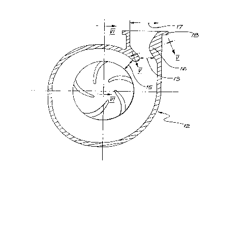
Figure 3 is a cross-section of a centrifugal slurry pump impe]ler
and casing according -to an embodiment of the present invention, said cross-
section being in a plane normal to the axis of impeller rotation;
Figure ~ shows a view of the casing flange and throat of Figure 3;
Figure 5 shows a section through the casing of Figure 3 at V-V; and
Figure 6 is a partial cross-section of a casing according to this
invention, said cross-section being in a plane through the axis of impeller
rotation.
Referring to Figure 1, the typical centrifugal pump casing (l)
has a gradually increasing radius of curvature starting from the cutwater (2)
through to a point tangential to the discharge neck (3). The impeller 4
spins within the casing having a smallest peripheral clearance at the cutwater
(5). The discharge neck area generaily increases from the throat (6) adjacent
to the cutwater through to the discharge flange (7).
The above described water pump casing (l) can be compared with a
conventional slurry pump casing (8) in Figure 2. The main differences are
readily apparent, with the increased cutwater clearance (9), and fair]y uniform
discharge neck area between the throat ~10) and discharge flange (ll) being
the most obvious. It can be seen that this design would readily allow flow
recirculation around the cutwater at reduced flowrates (w.r.t. BEP) because
of the open throat area and shape of the cutwater.
Figure 3 illustrates the preferred embodiment of a slurry pump
casing of the present invention which comprises a basically conventional
slurry pump casing (12) with an unconventional shape in the cutwater area. To
reduce the throat area (13) and stop recirculation the cutwater (14) is ex-
tendcd across the throat without greatly altering the cutwater clearance (15)
and a protrusion roughly convex in shape (16) is added to the opposing wall

~64~51
of thc discharge ncck. Thc resuitant gcometry leads to a reduction in the
throat area such that the ratio of throat area (13) to discharge area (17) is
in the range 0.3 to 0.7. The cutwater cleclrancc (15) is in the range of be-
tween S and 40% of the impeller diamcter, depending on the i.ndividual design
requirements.
Figurc 5 shows a section taken at a plane normal to the discharge
neck centreline as indicated in Figure 3. As can be seen the width 23 at the
discharge flange (1~) is approximately thc same clS the width at the throat (19).
i~owever the width of the throat can be between 50% and 100% of the width of
the discharge flangc.
Figure 6 shows a half section view VI-VI taken through the axis
of the impeller centreline as indicated in Figure 3. This view illustrates
the relationship between the impeller (20) and the pump casing (21). The im-
proved cutwater profile (22) is shown with its fillet radii blendillg continu-
ously at the apex of the cutwater and the casing side walls.
While this invention has been described in connection with the
preferred embodiment, it is understood that vari.ous modifications ~ay be made
without departing from the spirit of the invention.
-- 6 --

Dessin représentatif
Une figure unique qui représente un dessin illustrant l'invention.
États administratifs

2024-08-01 : Dans le cadre de la transition vers les Brevets de nouvelle génération (BNG), la base de données sur les brevets canadiens (BDBC) contient désormais un Historique d'événement plus détaillé, qui reproduit le Journal des événements de notre nouvelle solution interne.

Veuillez noter que les événements débutant par « Inactive : » se réfèrent à des événements qui ne sont plus utilisés dans notre nouvelle solution interne.

Pour une meilleure compréhension de l'état de la demande ou brevet qui figure sur cette page, la rubrique Mise en garde , et les descriptions de Brevet , Historique d'événement , Taxes périodiques et Historique des paiements devraient être consultées.

Historique d'événement

Description Date
Inactive : Périmé (brevet sous l'ancienne loi) date de péremption possible la plus tardive 2007-01-09
Lettre envoyée 2006-06-19
Lettre envoyée 2005-09-19
Inactive : TME en retard traitée 2003-12-18
Accordé par délivrance 1990-01-09

Historique d'abandonnement

Il n'y a pas d'historique d'abandonnement

Titulaires au dossier

Les titulaires actuels et antérieures au dossier sont affichés en ordre alphabétique.

Titulaires actuels au dossier
WEIR MINERALS AUSTRALIA LTD
Titulaires antérieures au dossier
ANTHONY GRZINA
Les propriétaires antérieurs qui ne figurent pas dans la liste des « Propriétaires au dossier » apparaîtront dans d'autres documents au dossier.
Documents

Pour visionner les fichiers sélectionnés, entrer le code reCAPTCHA :


Pour visualiser une image, cliquer sur un lien dans la colonne description du document. Pour télécharger l'image (les images), cliquer l'une ou plusieurs cases à cocher dans la première colonne et ensuite cliquer sur le bouton "Télécharger sélection en format PDF (archive Zip)" ou le bouton "Télécharger sélection (en un fichier PDF fusionné)".

Liste des documents de brevet publiés et non publiés sur la BDBC .

Si vous avez des difficultés à accéder au contenu, veuillez communiquer avec le Centre de services à la clientèle au 1-866-997-1936, ou envoyer un courriel au Centre de service à la clientèle de l'OPIC.


Description du
Document 
Date
(aaaa-mm-jj) 
Nombre de pages   Taille de l'image (Ko) 
Page couverture 1993-10-07 1 13
Abrégé 1993-10-07 1 10
Revendications 1993-10-07 3 79
Dessins 1993-10-07 2 42
Description 1993-10-07 6 172
Dessin représentatif 2001-06-29 1 11
Courtoisie - Certificat d'enregistrement (document(s) connexe(s)) 2005-09-19 1 104
Courtoisie - Certificat d'enregistrement (document(s) connexe(s)) 2006-06-19 1 105
Taxes 1995-12-18 1 53
Taxes 1996-12-18 1 67
Taxes 1994-12-14 1 70
Taxes 1993-12-16 1 48
Taxes 1992-01-09 1 42
Taxes 1991-08-22 1 35
Correspondance 1985-06-12 1 44
Correspondance 1986-04-14 1 24
Correspondance 1986-11-26 1 20
Correspondance 1989-10-10 1 28