Sélection de la langue

Search

Sommaire du brevet 1264258 

Énoncé de désistement de responsabilité concernant l'information provenant de tiers

Une partie des informations de ce site Web a été fournie par des sources externes. Le gouvernement du Canada n'assume aucune responsabilité concernant la précision, l'actualité ou la fiabilité des informations fournies par les sources externes. Les utilisateurs qui désirent employer cette information devraient consulter directement la source des informations. Le contenu fourni par les sources externes n'est pas assujetti aux exigences sur les langues officielles, la protection des renseignements personnels et l'accessibilité.

Disponibilité de l'Abrégé et des Revendications

L'apparition de différences dans le texte et l'image des Revendications et de l'Abrégé dépend du moment auquel le document est publié. Les textes des Revendications et de l'Abrégé sont affichés :

  • lorsque la demande peut être examinée par le public;
  • lorsque le brevet est émis (délivrance).
(12) Brevet: (11) CA 1264258
(21) Numéro de la demande: 1264258
(54) Titre français: MOTEURS BICARBURANT
(54) Titre anglais: DUAL FUEL ENGINES
Statut: Périmé et au-delà du délai pour l’annulation
Données bibliographiques
Abrégés

Abrégé anglais


ABSTRACT OF THE DISCLOSURE
An improved gas injection system for uniflow
dual fuel engines having a plurality of cylinders, a
piston in each cylinder, inlet ports arranged around each
cylinder to be uncovered by downward movement of the
piston in the cylinder is disclosed. It is comprised of
a seal located in one inlet port and a reed valve
assembly connected to the inlet port via the seal. An
inlet pipe connected to the reed valve assembly is
adapted to be connected at its distal end to a gas
source. An air inlet pipe is connected between the port
seal and the reed valve assembly for feeding air there-
between such that when the piston closes the one inlet
port, air from the air inlet pipe will close the reed
valve to prevent further flow of gas.

Revendications

Note : Les revendications sont présentées dans la langue officielle dans laquelle elles ont été soumises.


The embodiments of the invention in which an
exclusive property or privilege is claimed are defined as
follows:
1. An improved gas injection system for
uniflow dual fuel engines having a plurality of cylin-
ders, a piston in each cylinder, inlet ports arranged
around each cylinder to be uncovered by downward movement
of the piston in the cylinder, comprising:
a seal located in one inlet port;
a reed valve assembly connected to said inlet
port via said seal;
an inlet pipe connected to said reed valve
assembly and adapted to be connected at its distal end to
a gas source; and
an air inlet pipe connected between said port
seal and said reed valve assembly for feeding air there-
between such that when said piston closes said one inlet
port, air from said air inlet pipe will close said reed
valve to prevent further flow of gas.
2. An improved gas injection system as
defined in claim 1 wherein the gas inlet port extends at
an angle to the axis of the cylinder so that gas admitted
to the cylinder is directed toward the piston when the
latter is in its bottom dead centre position.
3. An improved gas injection system as
defined in claim 2 wherein said reed valve assembly
-7-

comprises a truncated conical fitting having a set of
openings closeable by means of a set of baffles laid
across the openings.
4. An improved gas injection system as
defined in claim 3 wherein said air inlet pipe is mounted
on an adaptor connected between said seal and said reed
valve assembly.
-8-

Description

Note : Les descriptions sont présentées dans la langue officielle dans laquelle elles ont été soumises.

1264;~
6613-6
This invention relates to uniflow dual duel
engines and more particularly to an improved gas injec-
tion system.
U.S. patent serial number 4,527,516 which
issued to J.S. Foster on July 9, 1985, discloses a
uniflow two cycle dual fuel engine. As disclosed in this
patent, the prolonged scavenge period of the two cycle
engine results in some unburned methane being carried
over into the exhaust system to the detriment of the
engines overall thermal efficiency, when operating in the
dual fuel mode.
The present invention provides a significant
improvement in the fuel efficiency of this type of
engine.
It is therefore an object of the present inven-
tion to provide an improved gas injection system which
will achieve improved thermal efficiency.
Another object of the present invention is to
provide an improved gas injection system able to prevent
the seepage and 1088 of gas around the piston/port area,
thereby improving the efficiency of the piston acting as
a gas injection valve.
Yet another object of the present invention is
to provide an improved gas injection system able to

1264~8
control and delay the timing of gas injection into com-
bustion chamber, thereby reducing the interval of time
available for methane to mix with scavenge air and hence
be carried unburnt into the exhaust system.
Accordingly, the present invention provides an
improved gas injection system for uniflow dual fuel engi-
nes having a plurality of cylinders, a piston in each
cylinder, inlet ports arranged around each cylinder to be
uncovered by downward movement of the piston in the
cylinder, comprising:
a seal located in one inlet port;
a reed valve assembly connected to said inlet
port via said seal;
an inlet pipe connected to said reed valve
assembly and adapted to be connected at its distal end
through a gas source; and
an air inlet pipe connected between said port
seal and said reed valve assembly for feeding air there-
between such that when said piston closes said one inlet
port, air from said air inlet pipe will be such as to
close said reed valve to prevent flow of gas.
Particular embodiments of the invention will be
understood in conjunction with the accompanying drawings
in which:
Figure 1 is a section through a conventional
uniflow two cycle diesel engine, modified for use with
--2--

12~ 5~3
dual fuel;
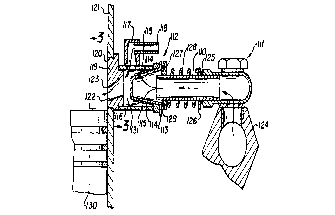
Figure 2 is a sectional detail of the improved
gas injection system of the present invention;
Figure 3 is a view taken along line 3-3 in
Figure 2; and
Figure 4 illustrates the typical timing diagram
for a uniflow two cycle diesel engine modified according
to the present invention.
The two cycle diesel engine illustrated in
Figure 1 is disclosed in U.S. patent serial number
4,527,516 and is to be considered as fully as if set
forth herein. In the present invention, the gas inlet
pipe 54 shown in Figure 1 which extends from the exterior
of the engine to and practically flush with the interior
of the cylinder 6, adjacent the piston 8 for the majority
of piston travel, is replaced by the improved gas injec-
tion system shown in Figure 2.
As shown in Figures 2 and 3, the gas inlet pipe
110 now extends between a banjo fitting assembly 111 and a
reed valve assembly 112. The reed valve assembly compri-
ses a truncated conical shaped fitting 113 having a set of
openings 114 made closeable by means of a set of baffles
115 adapted to cover openings 114.
Reed valve assembly 112 is fitted to an adaptor
116 provided with an air inlet fitting 117 connectable to a
rigid or flexible air line 118. Adaptor 116 is connected

lZ64;~i8
to port seal 119 received within the inlet port 120 of
cylinder liner 121. Port seal 119 is provided with an
inlet 122 located such that upper edge 123 is spaced
substantially below the upper edge of the inlet port 120.
Banjo fitting assembly 111 is secured to header 124 leading
to a source of fuel gas, for example propane or natural
gas, the latter being preferred. As shown in Figure 2
there is shown an 0-ring 125 around pipe 110 located bet-
ween a washer 126 and banjo fitting assembly 111. Washer
126 is a slide fit on pipe 110 and there is a fixed an~ular
flange 127 located on pipe 110. Spring 128 is located bet-
ween washer 126 and flange 127 to apply mild pressure to 0-
ring 125 and O-ring 129 located between flange 127 and
fitting 113.
In operation, when piston 130 has passed the
opening 122 of port seal 119, air entering chamber 131 from
the air inlet 117 will create a higher pressure than gas
pressure from header 124 and pipe 110, baffles 115 will
therefore rest against openings 114 of fitting 113 thereby
shutting off the flow of gas.
As piston 130 approaches the lower end of its
stroke, it uncovers the opening 122 of port seal 119,
allowing air from air inlet 117 to flow into the com-
bustion chamber. The subsequent drop in seal air
pressure in chamber 131 allows the reed valve assembly 112
to open, thus permitting gas to flow into the combustion

1264~58
chamber. As piston 130 rises and covers the opening 122 of
port seal 119, air pressure in chamber 13i rises, closing
reed valve assembly 112, again shutting off the gas flow.
Accordingly, it can be seen that air pressure
arriving from the air inlet 117 can be used to control the
timing and flow of gas into the combustion chamber of the
engine.
The engine's overall thermal efficiency is
therefore improYed in two ways. By shutting off the flow
of gas while the piston is above the port opening 122, the
seepage and 105s of gas around the piston/port area is
prevented. That is to improve the efficiency of the
piston to act as a gas injection valve. Also, by pro-
viding a means of controlling and delaying the timing of
gas injection into the combustion chamber, the interval
of time available for methane to mix with scavenge air
and hence be carried unburnt into the exhaust system is
reduced.
The engine timing diagram shown in Figure 4
emphasizes that the valve timing of the engine is not in
any way changed by the use of the improved fuel injection
system. The valve timing diagram is entirely conven-
tional and no further explanation is believed necessary.
Extensive research tests have established and
shown that the present invention improves the thermal
efficiency of the engine overall load and speed ranges.
--5--

4;~58
Similarly, it has been shown that the practical and com-
mercial aspects of this improvement reduces the "payback"
period on the initial capital investment necessary to
cover conversion cost.
As will be apparent to those skilled in the art
in light of the foregoing disclosure, many alterations
and modifications are possible in the practise of this
invention without departing from the spirit or scope
thereof. Accordingly, the scope of the invention is to
be construed in accordance with the substance defined by
the following claims.

Dessin représentatif
Une figure unique qui représente un dessin illustrant l'invention.
États administratifs

2024-08-01 : Dans le cadre de la transition vers les Brevets de nouvelle génération (BNG), la base de données sur les brevets canadiens (BDBC) contient désormais un Historique d'événement plus détaillé, qui reproduit le Journal des événements de notre nouvelle solution interne.

Veuillez noter que les événements débutant par « Inactive : » se réfèrent à des événements qui ne sont plus utilisés dans notre nouvelle solution interne.

Pour une meilleure compréhension de l'état de la demande ou brevet qui figure sur cette page, la rubrique Mise en garde , et les descriptions de Brevet , Historique d'événement , Taxes périodiques et Historique des paiements devraient être consultées.

Historique d'événement

Description Date
Inactive : Demande ad hoc documentée 1997-01-09
Le délai pour l'annulation est expiré 1996-07-09
Lettre envoyée 1996-01-09
Accordé par délivrance 1990-01-09

Historique d'abandonnement

Il n'y a pas d'historique d'abandonnement

Titulaires au dossier

Les titulaires actuels et antérieures au dossier sont affichés en ordre alphabétique.

Titulaires actuels au dossier
PRO-STAFF FUELS LTD.
Titulaires antérieures au dossier
JOSEPH S. FOSTER
Les propriétaires antérieurs qui ne figurent pas dans la liste des « Propriétaires au dossier » apparaîtront dans d'autres documents au dossier.
Documents

Pour visionner les fichiers sélectionnés, entrer le code reCAPTCHA :


Pour visualiser une image, cliquer sur un lien dans la colonne description du document. Pour télécharger l'image (les images), cliquer l'une ou plusieurs cases à cocher dans la première colonne et ensuite cliquer sur le bouton "Télécharger sélection en format PDF (archive Zip)" ou le bouton "Télécharger sélection (en un fichier PDF fusionné)".

Liste des documents de brevet publiés et non publiés sur la BDBC .

Si vous avez des difficultés à accéder au contenu, veuillez communiquer avec le Centre de services à la clientèle au 1-866-997-1936, ou envoyer un courriel au Centre de service à la clientèle de l'OPIC.


Description du
Document 
Date
(aaaa-mm-jj) 
Nombre de pages   Taille de l'image (Ko) 
Dessins 1993-10-07 2 62
Page couverture 1993-10-07 1 10
Abrégé 1993-10-07 1 15
Revendications 1993-10-07 2 28
Description 1993-10-07 6 123
Dessin représentatif 2001-04-02 2 20
Taxes 1994-11-30 1 35
Taxes 1993-12-09 1 28
Taxes 1992-12-17 1 26
Taxes 1991-12-23 1 28
Correspondance 1989-10-11 1 31
Correspondance 1988-11-25 1 35