Sélection de la langue

Search

Sommaire du brevet 1264511 

Énoncé de désistement de responsabilité concernant l'information provenant de tiers

Une partie des informations de ce site Web a été fournie par des sources externes. Le gouvernement du Canada n'assume aucune responsabilité concernant la précision, l'actualité ou la fiabilité des informations fournies par les sources externes. Les utilisateurs qui désirent employer cette information devraient consulter directement la source des informations. Le contenu fourni par les sources externes n'est pas assujetti aux exigences sur les langues officielles, la protection des renseignements personnels et l'accessibilité.

Disponibilité de l'Abrégé et des Revendications

L'apparition de différences dans le texte et l'image des Revendications et de l'Abrégé dépend du moment auquel le document est publié. Les textes des Revendications et de l'Abrégé sont affichés :

  • lorsque la demande peut être examinée par le public;
  • lorsque le brevet est émis (délivrance).
(12) Brevet: (11) CA 1264511
(21) Numéro de la demande: 1264511
(54) Titre français: ASPIRATEUR
(54) Titre anglais: VACUUM CLEANING APPARATUS
Statut: Périmé et au-delà du délai pour l’annulation
Données bibliographiques
(51) Classification internationale des brevets (CIB):
  • A47L 07/00 (2006.01)
  • A47L 11/30 (2006.01)
(72) Inventeurs :
  • ASHBY, DEREK (Royaume-Uni)
  • ALI, SAJJADALI GHULAMALI (Royaume-Uni)
  • FORWARD, RAYMOND JOHN (Royaume-Uni)
(73) Titulaires :
  • STEAM VACUMM EXTRACTION LIMITED
(71) Demandeurs :
  • STEAM VACUMM EXTRACTION LIMITED (Royaume-Uni)
(74) Agent: MARKS & CLERK
(74) Co-agent:
(45) Délivré: 1990-01-23
(22) Date de dépôt: 1985-02-07
Licence disponible: S.O.
Cédé au domaine public: S.O.
(25) Langue des documents déposés: Anglais

Traité de coopération en matière de brevets (PCT): Non

(30) Données de priorité de la demande:
Numéro de la demande Pays / territoire Date
8404051 (Royaume-Uni) 1984-02-16

Abrégés

Abrégé anglais


ABSTRACT
An improvement in the dry vacuum cleaning of soft
and hard surfaces in which vacuum only is applied to
such surface, is characterised in that dry soil flowing
away from such surface under the influence of vacuum is
sprayed with liquid and deposited in a wetted condition
in a liquid and soil-collecting vessel.
Also proposed is apparatus for cleaning hard and
soft surfaces by simultaneous application thereto of
liquid and vacuum using a tool and which is equipped
with a conversion device to permit dry vacuum cleaning
with entrainment of dry soil in the liquid for
subsequent collection in a soil and liquid vessel. The
device comprises a 2-way valve by which
liquid flowing through a first pipe can be caused to
flow alternatively to a head of a tool, or, through
at least one branch pipe to a second pipe or
pipe insert by which suction is applied to the head
of the tool to entrain the dry soil flowing therein.
The branch pipe or pipes normally terminate in one or
more spray nozzles and may be located at various
different positions in the path of flow of the dry soil
induced by vacuum.

Revendications

Note : Les revendications sont présentées dans la langue officielle dans laquelle elles ont été soumises.


THE EMBODIMENTS OF THE INVENTION TO WHICH AN EXCLUSIVE PROPERTY
OR PRIVILEGE IS CLAIMED ARE DEFINED AS FOLLOWS:
1. Apparatus for the dry or wet vacuum cleaning of
carpets and other fabrics and surfaces by selective
application thereto of vacuum only or vacuum and a
cleaning liquid such as hot water or liquid detergent in
which dirt from the fabric or surface becomes entrained,
comprising;
a cleaning head intended to be applied to the fabric
or surface;
a liquid and dirt-collecting vessel;
a first tube connected at one end to the cleaning
head and at the other end to a liquid supply source;
a second tube connected at one end to the cleaning
head and at the other end both to a source of vacuum and
to the liquid and dirt-collecting vessel;
at least one spray nozzle positioned between the
cleaning head and the source of vacuum in the path of
movement of dry dirt along the second tube and into the
liquid and dirt-collecting vessel; and
a conversion device connected to the liquid supply
source, the first tube and each spray nozzle;
the conversion device being manually operable
between alternative positions, in one of which the
liquid is permitted to flow to the cleaning head and in
another of which positions liquid is supplied only to
each spray nozzle to entrain the dry dirt which is
flowing under the influence of vacuum and to deposit

this entrained dirt into the vessel in a wetted
condition.
2. Apparatus as claimed in Claim 1 including a tubular
insert positioned in said second tube anywhere between
said cleaning head and said source of vacuum, and
wherein said at least one spray nozzle is positioned to
receive liquid through said tubular insert for injection
into the flow of dry dirt.
3. Apparatus as claimed in Claim 1 wherein said at
least one spray nozzle is positioned in said second tube
adjacent and outside said vessel.
4. Apparatus as claimed in Claim 1 wherein said at
least one spray nozzle is positioned in said second tube
inside said vessel.
5. Apparatus as claimed in Claim 1 wherein said vessel
has a vacuum sealing cover and said at least one spray
nozzle is positioned in said cover.

Description

Note : Les descriptions sont présentées dans la langue officielle dans laquelle elles ont été soumises.

4S~l
., ~
This invention rela~es to apparatus for the cleaninq
of soft and hard surfaces and of the kind which operate
by the simultaneous application thereto of liquid and
vacuum. Typical apparatus of this kind are described in
U.S.A. Patent Specification 3262146 ~nd our British
Patent Specifications 1448434 and 1497709. This kind o~
apparatus essentially comprises a tool which is
connected by a first pipe to a tank or other source of
liquid supply and by a second pipe to a source of vacuum
and a liquid-containing dirt-collecting vessel. In
operation the liquid is applisd on the surface to be
cleaned through a spray nozzle or nozzles located on or
within the tool and is continuously withdrawn with
entrained foceign mat~er, hereina~ter referred to as
"soil" under the effect of the vacuum. The liquid may
be water or some liquid solution.
The invention has been devised with the o~ject of
enabling ap~aratus of the aforementioned general kind to
be used also as a dry vacuum cLeaning apparatus, that is
to say withou~ application of liquid to the surface to
be cleaned.
In accordance with the invention there is provided
apparatus for the dry or wet vacuum cleaning of carpets

5~L~
and othe~ fabrics and suefaces by ~elective application
thereto of vacuum only or vacuum and a cleaning liquid
such as hot water or liquid detergent in which dirt from
the fabric or surface becomes entrained. The apparatus
comprises a cleaning head intended to be applied to the
fabric or sur~ace, a liquid and dirt-collecting vessel,
a first tube connected at one end to the cleaning head
and at the other end to a liquid supply source, a second
tube connected a~ one end to the cleaning head and at
the other end both to a source of vacuum and to the
liquid and dirt-collecting vessel and at least one spray
nozzle positioned between the cleaning head and the
source of vacuum in the path of movement of dry dirt
along the second tube and into the liquid and
dirt-collecting vessel. A conversion device is
connected to the liquid supply source, the first tube
and each spray nozzle and is manually operable between
alternative positions. In one of such positions the
liquid is permiteed to flow to the cleaning head and in
another such poæition liquid is supplied only to each
spray nozzle to entrain the dry dirt which i6 flowing
under the influence of vacuum and to deposit this
entrained dirt into the liquid and dirt-collecting
~essel in a wetted condition. The actual location of
the or each spray nozzle may be varied.

5~
. 2A
Also proposed in accordance with the inven~ion is a
conversion device assembly for fitting to a wet vacuum
cleaning appara~us and comprising a two-way valve having
an inlet tube connected to a liquid flow control valve
and a pair of outlet tubes of which one is connectable
to an apparatus cleaning head and the other is connected
to a spray nozzle which is receivable within the pipe by
which dirt is conveyed under vacuum to a dirt-receiving
vessel.
~he na~ure o~ the invention will hereinafter become
apparent from the following description of a preferred
embodiment of the invention to be described by way of
example and which is illustrated in the accompanying
drawings.

12~i4'rj~
.~ 3
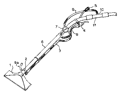
In these drawings; Fig. l is a schematic view of a
typical cleaning tool; Fig. 2, on an enlarged scale, is
a fragmentary view of a branch pipe connection: Fig. 3
shows some modes of fitting to a liquid and
dirt-collecting vessel and Fig. 4 illustrates components
of a conversion device assembly.
Referring now to the drawings, and particularly to
Fig. l, there is shown a tool of a liquid and vacuum
cleaning apparatus of the qeneral kind disclosed in the
already mentioned U.S.A. and British Patent
Specifications. The tool thus has a head l connected to
a source of vacuum by an elongated pipe 6. Secured by
clips 2 to the pipe 6 is a smaller diameter liquid
supply pipe 3 which hitherto was connected directly
through a control valve assembly 4, to the inlet pipe 5
either from a ~ank containing liquid or from some other
source of liquid supply such as a tap. As shown
however, the liquid supply pipe 3 is connected to the
valve 4 hy way of a conversion device comprising a
two-way valve 7 and a coupling pipe 8. The two-way
valve 7 is connected by a branch pipe 9 to a union lO
which extends radially through the wall of a tubular
member ll which has been inserted in the vacuum supply
pipe 6. The union terminates in at leas~ one spray
zs nozzle 12 which for example faces in the direction of
air f low as shown in Fig. 2. It could however face in
any direction.

~i4S~l
The valve 7 has a handle by which it may be moved
alterna~ively between a position in which it causes the
liquid to 10w along the pipe 3 to the surface to be
cleaned and an alternative position in which it causes
S the liquid to flow along the branch pipe 9 and into the
tubular insert 11 where it issues from at least one
spray nozzle ~2 and entrains the dry dirt which, under
the influence of the vacuum, is travelling through the
insert 11 as indicated by the arrow A. The liquid
solution with the dry dirt entrained therein di~scharge6
into the usual collecting vessel.
Fig. 1 shows that the branch pipe with its spray
no7zle oe nozzl~s may terminate in an alternative
position 9a directly behind the head 1 or in a position
9b actually at the front of the head of a tool as show~
in dashed lines.
Alternatively the branch pipe and the or each spray
nozzle could terminate anywhere alon~ the pipe 6 or in a
pipe connecting the latter to a source o~ vacuum.
Fig. 3 shows three further alternative positions of
the branch pipe and its associated spray nozzle or
nozzles. In one position (9c) there is a connection
through the vacuum sealing cover of a liquid and
dirt-collecting ~essel, whilst in the other positions
(9d) and (9e) there is a connection into a tubular
insert 11 which is located respectively inside and
outside the dirt-collecting vessel. In all instances
~ \ '

lX~i45~
where a tubular insert ll is used, the location of the
latter between the source of vacuum and the head of a
tool can be varied.
Further it is to be understood that there may be two
or moee branch pipes and/or two or more ~ubular inserts
ll connected at two or more of the alternative positions
which havs been mentioned above.
The conversion device which has been described and
which may take the form of an accessory kit (Fig. 4) has
been found to function most efficiently in tha~ when the
valve 7 is in the dry vacuum cleaning position the
advantage of dry vacuum cleaning is obtained without the
usual problems of dry dirt escaping from a dry
dirt-collecting container since the dry dirt becomes
suspended in or deposited with the liquid in the liquid
and dirt-collecting ves6el.
Thus the need for dry dirt or dust bags is
eliminated as also is the need for additional filtration
of the exhaust air flowing therefrom. A single machine
can thus ha~e two distinct modes of operation
However the entraining of dry dirt as aforesaid can
also be achieved without the use of a two way valve (7)
and branch line (9) by locating the liquid supply pipe
(3) ~o spray liquid anywhere in the positions mentioned
hereinabove.
~ \

Dessin représentatif
Une figure unique qui représente un dessin illustrant l'invention.
États administratifs

2024-08-01 : Dans le cadre de la transition vers les Brevets de nouvelle génération (BNG), la base de données sur les brevets canadiens (BDBC) contient désormais un Historique d'événement plus détaillé, qui reproduit le Journal des événements de notre nouvelle solution interne.

Veuillez noter que les événements débutant par « Inactive : » se réfèrent à des événements qui ne sont plus utilisés dans notre nouvelle solution interne.

Pour une meilleure compréhension de l'état de la demande ou brevet qui figure sur cette page, la rubrique Mise en garde , et les descriptions de Brevet , Historique d'événement , Taxes périodiques et Historique des paiements devraient être consultées.

Historique d'événement

Description Date
Le délai pour l'annulation est expiré 2005-01-24
Lettre envoyée 2004-01-23
Accordé par délivrance 1990-01-23

Historique d'abandonnement

Il n'y a pas d'historique d'abandonnement

Historique des taxes

Type de taxes Anniversaire Échéance Date payée
TM (catégorie 1, 8e anniv.) - petite 1998-01-23 1998-01-20
TM (catégorie 1, 9e anniv.) - petite 1999-01-25 1998-12-24
TM (catégorie 1, 10e anniv.) - petite 2000-01-24 2000-01-17
TM (catégorie 1, 11e anniv.) - petite 2001-01-23 2000-12-29
TM (catégorie 1, 12e anniv.) - petite 2002-01-23 2002-01-10
TM (catégorie 1, 13e anniv.) - petite 2003-01-23 2003-01-20
Titulaires au dossier

Les titulaires actuels et antérieures au dossier sont affichés en ordre alphabétique.

Titulaires actuels au dossier
STEAM VACUMM EXTRACTION LIMITED
Titulaires antérieures au dossier
DEREK ASHBY
RAYMOND JOHN FORWARD
SAJJADALI GHULAMALI ALI
Les propriétaires antérieurs qui ne figurent pas dans la liste des « Propriétaires au dossier » apparaîtront dans d'autres documents au dossier.
Documents

Pour visionner les fichiers sélectionnés, entrer le code reCAPTCHA :


Pour visualiser une image, cliquer sur un lien dans la colonne description du document. Pour télécharger l'image (les images), cliquer l'une ou plusieurs cases à cocher dans la première colonne et ensuite cliquer sur le bouton "Télécharger sélection en format PDF (archive Zip)" ou le bouton "Télécharger sélection (en un fichier PDF fusionné)".

Liste des documents de brevet publiés et non publiés sur la BDBC .

Si vous avez des difficultés à accéder au contenu, veuillez communiquer avec le Centre de services à la clientèle au 1-866-997-1936, ou envoyer un courriel au Centre de service à la clientèle de l'OPIC.


Description du
Document 
Date
(aaaa-mm-jj) 
Nombre de pages   Taille de l'image (Ko) 
Abrégé 1993-09-14 1 25
Revendications 1993-09-14 2 51
Dessins 1993-09-14 2 27
Description 1993-09-14 6 168
Dessin représentatif 2001-08-14 1 9
Avis concernant la taxe de maintien 2004-03-21 1 173
Taxes 2003-01-19 1 39
Correspondance 2000-01-31 3 54
Taxes 1998-01-19 1 39
Taxes 2002-01-09 1 62
Taxes 1998-12-23 1 28
Taxes 2000-12-28 1 33
Taxes 2000-01-16 2 53
Taxes 2000-12-28 1 31
Taxes 2000-01-27 3 48
Taxes 2000-01-20 1 21
Taxes 2000-01-16 1 33
Taxes 1998-12-23 1 28
Taxes 1998-01-19 1 46
Taxes 1995-12-11 1 46
Taxes 1995-02-28 1 45
Taxes 1997-01-21 1 42
Taxes 1995-01-17 1 39
Taxes 1995-02-12 1 14
Taxes 1995-01-29 1 19
Taxes 1994-01-23 1 33
Taxes 1993-01-20 1 35
Taxes 1994-01-13 1 21
Taxes 1992-01-30 1 50
Taxes 1992-05-20 1 44
Taxes 1992-04-13 1 35
Taxes 1998-12-14 2 59
Taxes 1999-02-22 3 46
Taxes 1998-01-19 3 84
Taxes 1997-12-17 3 76
Taxes 1995-11-22 3 62
Taxes 1996-11-27 3 85
Taxes 1995-05-23 2 82
Taxes 1995-03-27 1 22
Taxes 1995-03-20 1 10
Taxes 1994-09-05 1 29
Taxes 1994-09-13 1 13
Taxes 1994-01-20 1 12
Taxes 1994-01-04 1 29
Taxes 1994-01-23 1 28
Taxes 1994-03-20 1 14
Taxes 1993-12-09 1 17
Taxes 1994-03-06 1 23
Taxes 1993-11-24 1 32
Taxes 1991-12-18 1 15
Taxes 1993-01-18 1 33
Taxes 1992-03-16 2 146
Taxes 1992-03-19 1 46
Taxes 1992-03-16 1 23
Taxes 1991-12-10 1 33
Taxes 1992-02-27 1 30
Taxes 1993-01-12 1 68
Taxes 1992-01-21 2 64
Taxes 1992-03-09 1 28
Taxes 1992-02-18 1 28
Taxes 1992-02-19 1 19
Taxes 1993-01-10 1 24