Note : Les descriptions sont présentées dans la langue officielle dans laquelle elles ont été soumises.
~ 2~5~L23
1/
MECH~NICALLY ACTUATED WHIPSTOCR ASSEMBLY
Background of the Invention
This inv~ntion relates generally to earth well drilling
apparatus and and its use. Particularly, it relates to
apparatus that is useful for drilling one or more bore
holes extending laterally from a lower region of a well
into a mineral bearing formation.
It has been recognized that minerals may be recovered
from mineral-bearing formations by introducing such
agents as steam, hot water, chemical solutions and the
like. For example steam has been introduced into pe-
troleum-bearing sands (e.g. tar sands or heavy oil) and
other porous formations to effect the release and removal
of petroleum not otherwise having sufficient fIuidity to
permit pumping from the well. Certain of such equipment
and methods employ special drilling apparatus for drill-
ing a laterally extending bore from a region of the well
at the level of the formation, after which steam ox other
- treating fluid is introduced into the bore. An example
of such drilling apparatus is disclosed in U.S. patents
; 2,258,001 and 1,865,853. Such prior drilling equipment
and methods have been subject to certain disadvantages.
In instances where drilling the lateral bore has employed
a rotated cutting head which is directed laterally
against the formation, the torque may be applied to the
head through driving means extending from the top of the
well, which requires complicated and expensive means to
~ ,
:
,,:
:
~2Ç~23
2--
transmit power through a vertically rotated pipe or shaft
to the laterally directed drillhead. If an electrical
driving motor is located within the well and coupled to
the drillhead, it poses problems in applying the
necessary electrical energy and the motor may not be
readily salvageable before injecting steam or other
treatment fluid. Vse of laterally directed jet drilling
as shown in U.S. Patent 2,258,001 requires special
flexible piping which carries the drillhead and to which
hydraulic liquid under pressure is applied. Among other
objections, flexible conduits are not self-supporting
when projected laterally and thus require additional
supporting means such as a surrounding housing as shown
in Patent 2,258,001.
EPA Publication 0 100 230 discloses an apparatus and
method making use of hydraulic jet drilling with the
drillhead being attached to a drilling tube of the solid
wall type. The drilling tube initially is carried within
piping extending downwardly into the well and has an open
upper end. A seal is provided ~etween the drilling tube
and the piping, whereby when hydraulic liquid (e.g.
water) under pressure is applied to the piping, it is
propelled downwardly. Tube bending means is carried at
the lower end of the piping adjacent the mineral bearing
formation, and forms an arcuate guide way through which
the drilling tube is propelled, thereby causing the
drilling pipe to be bent and the drilling head projected
laterally into the formation.
- The EPA Publication 0 100 230 also discloses a retract-
able whipstock consisting of connected assemblies, which
when extended from a retracted position within the
structure form an arcuate tube bending guideway. The
assemblies have a series of rollers or sheaves rotatably
carried to form a segment of the arcuate guideway. The
form of the guideway is generally that of an arc of a
... .
:
: '
~q 2~S~23
-3-
circle extending to one side only of the apparatus. The
segments are formed into the arcuate pathway by applying
hydraulic forces from the surface to a hydraulic piston
- assembly.
Jeter Patent 4,007,797, purportedly discloses, in Figure
10 an erectable whipstock (conductor) which projects to
both sides of the assembly in which it is contained prior
to erection. An attempt to use the Jeter erectable
conductor would result in a number of major problems.
One problem with the conductor of Jeter is that the
guidet being flexible, and being held by a single ac-
tuating rod (80), is incapable of resisting moments
required to bend a solid tube. A further problem with
Jeter is the use of a piston which acts axially with
respect to the drill pipe. Therefore, actuating rod 80
must be relatively short and at a sharp angle to the axis
resulting in high stress on rod 80 to bend the rigid
pipe. Furthermore, arm 80 is illustrated on the left
(top) side of the conductor in Figure 8 in an unerected
position and of the bottom side in Figure 9. Obviously,
this is a paper not real, solution to the erection
problem.
Another problem with Jeter is that it includes no rollers
or sheaves to engage the inner or outer walls of the bent
tube to reduce frictional forces which can otherwise
either prevent the tube from bending through the whip-
stock or cause the tube to buckle in the whipstock.
Perhaps recognizing this, Jeter suggests column 10, line
44-52 that the pipe be flattened as it moves through the
whipstock and is thereafter reformed into a circular
shape. Rigid pipe is not likely to be capable of such
drastic changes in shape on moving through the whipstock.
'
~.,~ ..
.
~L2~5~3
Summary of the Invention and Objects
The present invention is directed primarily to a system
for the form~tion of a bore hole for use in the recovery
or enhancement of recovery of oil from an oil-bearing
formation, or for the recovery of mineral deposits or the
like, or for drilling through an underground formation
for some other purpose. Specifically, the system relates
to structure including a number of collapsed connected
guideway assemblies fitting within the well bore. The
structure also includes a retractable anchor means
connected to the rear side of the guideway assembly and
erection means also slidable in the assembly. The
erection means i5 pivotally connected to a forward one of
the guideway assemblies and the other end to an extension
member extending to the earth surface. When the system
reaches the desired position adjacent the formation, the
anchor means is locked into the earth well and the
erection means is pulled by an extension arm from the
surface to cause a forward one of the guideway assemblies
to be pivotally swung so that the guideway assemblies in
composite form a curved pathwa~ extending into the
formation. Within the pathway are a series of sheaves or
rollers. In the preferred embodiment, the pathway is in
an inverted comma shape with portions extending to both
sides of the assembly.
After erection, a drilling tube is passed through the
whipstock into the formation and is used for steam in-
jection. The tube is cut near the whipstock exit for
production and the portion of the tube in the whipstock
is pulled back from the surface. The present system also
includes a deerection system whereby the extension arm is
again lowered to cause the guideway assemblies to move
back into their retracted position, the anchor means is
collapsed, and the entire assembly can be moved to
.
~265~23
5~
another position wlthln the well or pulled to the sur~ace. It iæ
an object of the inventlon to provide whlpstock mean~ which can be
lowered into an sarth well in a collapsed position and extended at
the desired depth using mechanlcal forces.
It is another object of the invention to provide a
system for erecting a whipstock wlth precision with the desired
pathway into the formation by applying pulling forces at the
surface.
It is another object of the invention to provide a
system of the foregoing ~ype capable of deerection by mechanical
forces.
It is another object of the invention to provide a
system of the foregoing type which is capable of forming a
whipstock ln an inverted comma shape to both sides of the
whipstock ~o decrease the amount oE underreaming required.
In accordance with a broad aspect of the invention there
iæ provided earth well drilling means apparatus comprising
structure including whipstock means adapted to be positioned
within an earth well ad~acent to a mineral bearing formation, said
whipstock means comprising a plurality of connected guideway
a~semblies laterally extendible from a retracted position
substantially within the outer well to an extended position
forming a curved tube bending guideway, piping with the well to
whlch said whipstock means is attached, anchor means operatively
connected to the rearward side of said whipstock mea~s and having
a retracted position for sliding through sald earth well and an
anchoring position for locking ln a fixed position relatlve to
B sald earth well, and erection means slidable within said earth
~2~ 3
5a ~
well, said erection means being plvotally connected at one end to
a forward one of said guldeway assemblies and at the other end to
extension means extending to the ear~h surface, said pivotal
connection being of a type to cause said guideway assemblles to
swlny into said curved pathway when said extension means is pulled
from the earth surface with said whipstock means fixed at its
rearward end.
In accordance with another broad aspect of the lnventlon
there is provlded a method of forming earth well drilllng
apparatus for placlng a radlal tube laterally into a mineral
bearing formatlon from an earth well whlch extends downwardly from
the surface of the formatlon to the region of radlal tube
placement, sald method making use of a structure comprising
whipstock means including a plurality of connected guide
assemblies laterally extendible from a retracted position
substanti.ally within the earth well to an extended posltion
forming a curved tube bending guldeway for a drilling tube to be
extended radially into the formation, anchor means operatlvely
connected to the rearward side of said whipstock means and having
a retracted position sliding within said earth well and an
anchoring position for locking in a fixed position relative to
said earth well, and erection means slideable within said earth
well, said erection means being pivotally connected to a ~orward
one of said guide assemblies and at the other end to ex~ension
means extending to the earth surface, said method comprising
moving said whipstock means adjacent to the mineral bearing
formation with said whipstock means and anchor means in a
retracted position, moving said anchor means into said anchorlng
~ .
~2~S~23
5b
position and pulling from the earth surface on sald extension
means of said erection means to cause said forward one of said
guide assemblles to pivot away from said well to a sufficient
extent to form said curved tube bending guideway, together with
the step of moving a drilling tube through said guideway to cause
it to bend and pasæ into said formation forming a radial tube.
Additional objects and features of the invention will
appear from the following description in which preferred
embodiments have been set forth in detail in conjunction with the
accompanying drawings.
Brief Descrip~lon of the Drawings
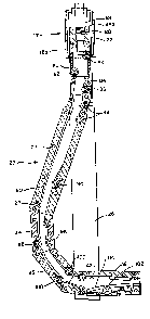
Figure 1 is a schematic view in side elevation
illustratlng the apparatus disposed within earth well with the
drilling tube extended ln a lateral hole.
Figure 2 is a detailed vlew in side elevation
illustrating the whipstock in a collapsed position within its
mounting.
Figure 3 is a detailed view in side elevatlon
illustrating the whipstock assembly in its extended position.
--6--
Figure 4 is a detailed sectional ~iew of the whipstocX
portion of the device illustrating the interior bending
surfaces and wheels.
Detailed Description of the Preferred Embodiments
Figure 1 schematically shows an earth well 10 which
extends down to the mineral bearing formation 12. In
this instance, the well is shown provided with a casing
14 which may extend down to an underreamed cavity 16 that
is adjacent to the formation 12. Structure 17 includes
piping extending in the well consisting, in this in-
stance, of outer piping 18 in the form of a pipe string
with a lowermost section 18a shown in Figure 2, within
which a drilling tube 20 is normally disposed. As shown
in Figure 4, a seal 22 is mounted within the pipe string
and forms a seal between the pipe string and drilling
tube 20. The upper end of the drill pipe is above seal
22 when the drilling tube is retracted. Before the
drilling tube is extended, it is within pipe string 18
with its drilling head 24 located below seal 22. Struc-
ture 17 also includes housing 26 serving to carry whip-
stock means 28. Seal 22 is preferably incorporated into
the coupling adjacent the upper end of whipstock means
28. Alternatively, it may be disposed in some other
portion of outer piping 18. Figure 1 also schematically
shows a production rig 30 of the mobile type and a reel
carrying truck 32 which may carry a supply of drilling
tube 20, which brings supply drilling tube for use in the
well but is not connected during placement of the drill-
ing tube~
As shown in Figures 2, 3 and 4, housing 26 carries five
bending assemblies 30, 32, 34, 36 and 38 pivotally
connected at hinges. Housing 26 contains the whipstock
means in a deerected position, anchor means and means for
; erecting and deerecting the whipstock means as described
hereinafter. Outer piping 18 includes clearance for the
: ~ '
~2~ 3
whipstock means to be erected. As illustrated in Figures
1, 3 and 4 clearance is to the left and right of the
whipstock. By using whipstock sections 30, 32, 34, 36
and 38 of rectangular shape, housing 26 is in the form of
flat rigid side plates 40 interconnected at the bottom by
lift pin 42 and at the top by bolts 44 mounted to the
interior piping and assemblies as described below. Lift
pin ~2 is pivotally connected to the most forward whip-
stock segment 38.
Referring specifically to Figures 1 and 2, housing 26 is
lowered into casing 14 until it reaches the desired
position adjacent to formation 12. All components of
this system are contained within the structure during
such passage in a manner that permits the system to be
lowered through a preexisting casing.
Referring again to Figure 2, anchor means 46 is illus-
trated in a retracted position within the casing with the
whipstock means deerected. Anchor means 46 i~ operat-
ively connected to the rearward side of whipstock means
28. In the illustrated retracted position, it slides
within the earth well. In the anchored position illus-
trated in Figure 3, it locks in a fixed position relative
to the earth well and causes the whipstock means 28 to
raise from the fixed anchor position and thus, lift pin
42 can be raised during erection as described below.
One significant feature of the system is that there is
relative movement between casing 10 and inner piping 48
which is used to actuate erection and deerection of the
whipstock means 28. Thus, when a part is described as
being mounted to the inner piping, it moves when that
part moves. The only part in the system which is not
fixidly mounted is the anchor means which functions as
set out below.
,, ~ ^ . .
:
~2~5~L~3
--8--
Inner piping 48 is mounted in outer piping 18 and, in
combination with other portions of structure 17 serves to
anchor, erect and deerect whipstock means 28. Inner
piping 48 is threadedly connected at its forward end or
lowermost segment the top segment 30 of whipstock means
28.
The system also includes deerection means comprising an
upper deerection spring 52 and a lower deerection spring
54. Upper deerection spring retainer 56 is mounted to
inner piping 48 and includes a lower shoulder 56a for
retaining spring 52. An erection sliding seal 58 i9
mounted to the interior of inner piping 48 to maintain a
seal with the drilling tube when the system is erected as
described below. A lower spring retaining ring 60 is
mounted to outer piping 18. Similarly, an upper spring
retaining ring 62 is mounted to inner piping 48 while a
lower spring retaining ring 64 is mounted to outer piping
18. Springs 52 and 54 provide the same kind of compres-
sive forces for erection and deerection of the system as
described below. They function in a similar manner and
are additive in their compressive forces. If desired, a
single spring could be utilized with the desired amount
of force.
Anchor means 46 is the only portion of the illustrated
apparatus that is not fixidly secured to either outer
piping 18 or inner piping 48. Components of anchor means
46 are drag springs 66 slidably carried by inner piping
- 48 and projects through slot 67 in outer piping 18 to
ride against casing 14 while the assembly is being
lowered into position. Drag springs 66 serve to center
the overall unit and to provide sufficient frictional
force against casing 14 to permit the anchor to lock
into position against it when outer piping 18 is pulled
upwardly as described below.
.,.,. ''
. .
- ~ 2~ L23
_9
Anchor means 46 also includes anchor jaws 68 with a saw
tooth-like outer surface 68a for embedding into casing 14
when urged outwardly as set out below. The interior
surface of anchor jaws 68 are sloping walls 68h which
slope inwardly in an upward direction to provide a
surface against which a correspondingly sloped ramp may
act. Jaws 68 are slidably mounted to ride on inner
piping 48 and are spring mounted so that they are urged
inwardly unless actuated. When the system is lowered to
the desired elevation adjacent the formation in the
position illustrated in Figure 2, anchor jaws 68 are out
of registry with vertical slot 67 and so are retained
within outer piping 18 by abutting against the adjacent
wall of that structure. Such anchor jaws are are the
same elevation as the vertical slots so that when it is
desired to anchor the system, outer piping 18 is rotated
relative to inner piping 48 causing the anchor jaws to
move into registry with such slots whereby they are urged
outwardly against the casing.
A jaw extension ramp 70 is mounted to outer piping 18
including a sloped upper wall 70a of a shape which mates
with the inner sloping wall 68b of anchor jaws 68 to
cause the anchor jaws to be urged outwardly when ramp 70
is moved upwardly relative to the jaws.
The operation of anchor means 46 is as follows. When the
desired elevation adjacent to the formation is reached,
the outer piping 18 is rotated relative to inner piping
48 to permit anchor jaws 68 to move into registry through
their corresponding slots. The slots extend a su~ficient
distance below jaws 68 to permit upward movement of outer
piping 18 to erect the system as described below.
Structure 17 is pulled by an extension arm 72 which may
comprise a pipe which extends all the way to the surface.
Extension arm 72 includes a passage through which the
drilling tube projects as described below. When
5~23
10-
extension member 72 i5 pulled upwardly, both the outer
piping 18 and inner piping 48 are correspondingly pulled
because they are connected at lifting pin 42. With the
jaws in the slot, drag spring 66 provides sufficient
resistance against upward movement that anchor jaws 68
begin to be locked into an embedded position in the
casing wall when urged against the wall by jaw extension
ramp 70 as the inner piping is pulled upwardly. Outer
piping 18 is not affected because of the slot clearance.
Once the system is anchored, whipstGck means 28 begins to
erect because lift pin 42 is being moved upwardly while
the top segment 30 of whipstock means 28 is being re-
tained in a fixed elevational position by anchor means
46. Since guideway assembly 38 is pivotally mounted to
lifting pin 42 and because lifting pin 42 is mounted
eccentrically (towards the left hand side as illustrated)
segment 38 begins to pivot to the left until the sloping
upper wall 38a contacts the corresponding lower wall 36a
of guideway assembly 36. Such pivoting begins at the
bottom rather than the top because the lower piping
segment 18a forms a shroud which maintains upper guideway
assembly 30 in a fixed position during the initial
erection. This permits the system to be erected into the
desired configuration. Thereafter, after erection is
begun, piping segment 18a clears upper guideway assembly
30 to permit it to be erected as illustrated in Figure 3.
Springs 52 and ~4 are partially compressed prior to
lowering of the system into the earth well. This serves
to maintain whipstock means 28 in a straight line de-
erected configuration within side plates 40 for passagethrough the earth well by keeping the whipstock in
tension. During erection, by pulling of the outer
causing upwardly, upward retaining rings 56 and 62, being
mounted to inner piping 48 are in a fixed elevational
position while lower retaining rings 60 and 64, being
.,,
5~23
--11--
mounted to outer piping 1~ move upwardly to cause springs
52 and 54 to be further compressed. This assists in
deerecting the system as described below. Such
additional compression also stiffens the system which
applies a strain load on the whipstock means to streng-
then the hinges in the erected position.
Whipstock means 28 may be maintained in an erected
position by insertion of a slip collar at the surface.
When deerection is to be accomplished, the slip collar
(not shown) is removed to permit the outer structure to
move downwardly.
Referring to Figure 4, a detailed view of the erected
whipstock is illustrated. At the top of the whipstock is
a high pressure seal which provides piston-like forces to
push the piping through the whipstock and into the
formation in the manner described with respect to U.S.
patent 4,527,639, in~^rr~r~ h~rcin by -~e~e~e~
Briefly sum~arized, high pressure fluid is directed
against a fluid pressure bearing area to the rearward
side of the drillhead which is of the hydraulic jet type,
including one or more jet type openings. When the
drilling tube is forced through the whipstock, bending
forces are applied to cause the tube to conform generally
to the curve of the whipstock so that the tube is caused
to turn into the formation. The pressurized drilling
fluid presses against the seal and the portion of the
guide pipe upstream from the seal so that the force is
directed against the rearward side of the drill head
cause it to project in a forward direction.
3Q Whipstock means 28 functions as follows: Above seal 22 is
a guide ring 80 which guides drilling tube 20 through the
seal 22 and allows water to enter a bypass system whereby
water can be used to flush the small annulus between the
interior guide walls of the whipstock and the drilling
` '~
:
. .
23
-12-
tube. Prior to application of the hydraulic forGes, the
drilling tube is placed into the seal. Then, the system
is pressurized so that drilling tube 20 moves past the
first two wheels 82 in the system. Then, the drilling
tube contacts the first ramp 84 in guideway assembly 30
which causes a bending action toward the backside of the
whipstock means and loads the third wheel 86 in guideway
assembly 30.
The drilling tube now enters guideway assembly 32 and is
guided by the first two wheels 88 causing the drilling
tube to be guided along the ramp of that section until it
hits the last xamp 90 just above the last wheel 92 to
force the drilling tube to load onto wheel 94 and start
the bending motion of the drilling tube toward the right
hand side of the drawing. Wheels 92 and 94 provide the
initial bending of the drilling tube into about a one
foot radius which allows it to move through guideway
assemblies 34 and 36 without substantial additional
bending moments.
Wheels 98 in guideway assembly 34 and wheels 100 in
guideway assembly 36 act as guide wheels to position
drilling tube 20 relative to guideway assembly 38 which
serves as a straightener. The ramps in guideway as-
semblies 34 and 36 assist in loading the drilling tube 20
onto such wheels if the bending is not sufficiently
precise. As drilling tube 20 exits guideway assembly 36,
it is guided by the wheels in that segment to cause the
drillhead to contact the ramp at the bottom of guideway
assembly 38 which loads the drillhead onto straightener
wheel 102 mounted in carriage 104 which forces the
drillhead to the top of segment 38 and causes it to move
into the formation in a straight line. Carriage 104 is
adjustable so that by calibration, the position of wheel
102 may be set so that the drillhead proceeds hori-
20ntally into the formation or at any desired angle.
.~
~26~ 23
-13-
One advantage of whipstock means 28 is that it projects
to both sides of the housing and so less underreaming is
required than if it projected only to one side. As il-
lustrated, the whipstock means assumes an inverted comma
shape with the drillhead turning at a relatively sharp
angle just prior to moving into the formation. Under-
reaming may be accomplished in a conventional manner.
Another advantage of the internal mechanism of the
whipstock means is that due to the unique use of rollers
and slides, the friction is low, the drillhead can make
the initial turn without damage and the drilling tube is
maintained in a relatively round configuration during the
turning. The use of the wheels and ramps permits this to
be accomplished with minimum flattening of the system.
A significant advantage of the present system is that the
whipstock means is erected by the simple mechanical force
of pulling ~rom the surface rather than by the use of a
hydraulic cylinder to cause erection. One advantage of
such erection is the precise knowledge that the whipstock
means is fully erected to permit the radial to move
hori~ontally into the formation. This is Xnown because
when the outer structure is pulled upwardly at the
surface a predetermined distance for full erection, the
whipstock is erected. This is to be contrasted with
hydraulic cylinders which are not as precise in their
operation due to leaks and the like. Also, since there
is a continuous string to the surface, pipe stretch does
not affect the function of erection.
The system of the present invention is also capable of
ready deerection to either move structure 17 to another
portion of the same earth well or to pull it totally out
of the earth well for reuse in another earth well. In
essence, deerection is accomplished by releasing the
S~23
-14- 1
anchor means from the casing, causing the inner piping to
move downwardly relative to the outer structure and
thereby moving lifting pin downwardly to pull the seg-
ments of the whipstock into a straight line as illus-
trated in Figure 2. Springs 52 and 54 are maintainedunder sufficient compression so that even during de-
erection, the segments of the whipstock means are
maintained under tension to prevent spontaneous erection
of the system.
During deerection, the outer structure is moved down-
wardly causing lift pin 42 to move correspondingly
downwardly and to move the whipstock means into a
straight line or retracted position. With the whipstock
means in a straight line, continued lowering of the outer
structure 26 causes inner piping 48 to be pulled down-
wardly at lift pin 42 and thereby causing ramp 70 to move
downwardly out of engagement with the corresponding inner
walls of 68b of jaws 68. In this manner, jaws 68 coll-
apse against inner piping 48. Then, outer structure 26
is rotated relative to jaws 68 to cause the jaws to move
GUt of registry with the corresponding slot and to be
thereby retained in a retracted position by adjacent wall
segments of the outer structure. With the jaws 68
prevented from locking against the inner wall of casing
14, the entire unit may be lifted up out of the earth
well.
Should the above deerection system not work due to sand
clogging of the jaw slots or the like, backup systems may
be provided. In one backup system, jaw extension ramp 70
is mounted to inner piping 48 by shear pin 110. If the
jaws will not release in a manner set out above, suf-
ficient pushing force is applied from the surface against
structure 17 to shear the shear pins and cause ramp 70 to
fall out of engagement with jaws 68. For this purpose,
support spring 112 is provided below the ramp 70 which is
. "
~:
'
~5~23
--15--
sealed by upper and lower wiper rings 114 and 116 re-
spectively against sand from moving into the system. In
this manner, when shear pins 110 are shearea, ramp 70 may
- fall a sufficient distance to release jaws 68 due to the
clearance provided by spring 112.
As set forth above, during erection of the whipstock,
outer piping moves upwardly relatively to fixed inner
piping 48. Therefore, a potential gap may be created
between the uppermost segment of piping 48 and the
drilling tube moving through the piping. It is essential
to maintain a hydraulic seal in order to utilize the
piston-like forces described above to push the drilling
tube through the inner piping and out the whipstock by
hydraulic forces. Accordingly, sliding seal 58 is
mounted to the outer piping 18 to provide a high pressure
hydraulic seal to prevent any gap during relative move-
ment of the outer piping and inner piping.
In operation of the present system, a radial is placed in
the desired mineral bearing formation, typically in an
oil field. The surrounding formation may be heated as by
injection of steam and oil is caused to flow either back
to the same well or towards another production well. In
typical operation, prior to production in this manner,
the drilling tube portion projecting into the formation
is severed near the whipstock by conventional means. In
order to deerect the system, the drilling tube is first
removed from the whipstock section by pulling upwardly
- from the surface. This, of course, is facilitated by
first severing the portion of the drilling pipe project-
ing into the formation. Thereafter, deerection is ac-
complished as set forth above.
The above system is particularly effective when used in
conjunction with a drilling pipe propelled by hydraulic
forces as set forth in above. For that purpose,
.~, .
~ , '
:~ .
.
~S123
-16-
hydraulic seals are provided in this system to accomplish
the piston-like effect. However, it should be understood
that the system may also be employed to move a radial
pipe into the formation by some other means~
, .
,: