Note : Les descriptions sont présentées dans la langue officielle dans laquelle elles ont été soumises.
~2~ 6
The devlce of the present invention relates to
cryogenically ~ooled detector assemb].ies, and, more
particularly, to miniaturi2ed cryogenically cooled
detector assemblies used for th rmal imasing systems.
In most thermal imaging systems using semiconductor
detection devices, it is necessary to place the detectors
in a vacuum environment for two reasons: first, to
protect the detectors from condensation of gases, since
the detectors operate at cryogenic temperatures, and
second, to minimize heat load to ~he cryogenic
refrigerator by these same gases. : In the past, ~ the
cryogenic cooler (or~ ~refrigeratorn) design and general
pack1ng~ requirements have been~ such that the detector
~dewar/refrlgerator~ was economlcal~ly ~ nonexpendable.
Because~ of the refr~gerator~ size~ the packa~ging of the
system was generally large, and, therefore, the total
system ~costs were high.~ Since~the package design and
weight were~ large~,~the~cool-down~ time~ for these ~sy~tems
w~s~ atl _ly~long.
A5~a~re5~ult~the;~use 0f cryog5nlcally cooled lnfrared
dete;ctors~was limlte;d~to ~applicatlon~5~in~whlch~cool-down
:
:
:
:~ :.:: , . : :: , . , :
~2~3~
time and portability are not critical, and in which the
detector system is reusable, for ex~nple~ in airborne
infrared reconnaissance cameras, tank or periscope
sights, etc. The cost, size, weight and cool-down time
s of such systems have, for the most part, barred their use
in small heat-seeking munitions.
Recently, a fast cool-down, low cost ~microminiature"
refrigerator has become commerlcally available, which, if
packaged properly with infrared detectors makes possible
the use of detection assemblies in a variety of sn~all,
low cost applications. These applications include
infrared binoculars, munitions, and other either highly
portabLe or expendable applications. The theory and
design of the refrigerator has been f ully described by
Robert Wolfe and Robert Duboc, Jr~, "Small Wonders:
Micromlniature Refrigerators~ for~ Cooling Detectorsn,
Photonics Spectra, July, 19~3.~ A ~brief~summary of these
~M~ ~ -devices is inciuded here as background to the apparatus
of the present invention.
::
:
20~ Like the prior art refri~gerators typically used in
infrared imagi~ng ~ systems,~ the ~ ~new ~mlcrominiature
refrI~gerator~ opera~es~ ~on ~the ~ prlnciple~ ~ of the~
oule-Thomson effect-. ~Gas at high pressure is expanded~
~a~6S3~L6
--3--
rapidly through a small orifice and therefore cools. The
cooled gas is passed through a heat exchanger to precool
the high pressure incoming gas, which provides lower
temperature during expansionO This regenerative process
continues to the liquification temperature of the gas.
In prior imaging systems, a typical refrigerator was
embodied in a long cylindrical ~cold finger" consisting
of capillary tubes and cooling fins, wherein the cooling
function was directed to the end of the cylindrical cold
10 finger. To complete the refrigerator, a close fitting
closed cylinder was required to contain and direc~ the
cold exhaust gas over the incoming high pressure gas in
the heat exchanger area. This closed cylinder of precise
diameter and length is incorporated into the detector
dewar. The closed end is the det~ector~support. A vacuum
container surrounds the cylinder to limit heat flow and
condensatisn.
These~ prior ~art refrlgerators have several problems
which make them~;impractical for ose ln small portable or
expendable eystems.~ First, the size o~ the refrigerator
nece~ssari~ly leads to;~a large ~package~ tdewar) slze.
Second,~because~ of~th~e~large dewar slze and the mass of
associated components,~ the~se~ deYices generally require
several ~minutes ~ to achieve ~ operating cryogenic
: ~: ; ~ ;
: ~ ~
i3~
--4-- .
temperature~ Third, the cost is increased because of
several factors~ For examplet the cost to pro~ide the
precision diameter of the closed cylinder is increased.
Also, the closed cylinder is approximately two (2~ inches
long so that, although the detectors are small, the
package must be large in order t:o contain the
refrigerator and must be of ~recise size. Further, since
the area of the refrigerator is large, the surrounding
gas must be removed, i.e., a vacuum is required, all of
which increases cost. Thi~ vacuum must be maintained
over the desired life of the system so that thermal
conduction through the vacuum space will not increase the
refrigerator temperature. The detector sitting on the
end of the cold finger must be located accurately with
respect to the optical system~. To achieve this pr cise
position many parts of the detector dewar require~ close
: ~ tolerance manuacture and special assembly jigs.
Finally, obtainlng a hard vacuum requires~ glass-to-metal
seals,~ weIds, solder joints or brazes which are
;20 ~ relatively expensive. ~ :
In: the microminiature ref~igerator design, the
capillary~ tube~and~:expans1on~ cham~ber~system ~comprising
the :Joule~Thomson~ refrigerator~ is embedded in a low
thermally conductive~ s~ubstrate, such as glass. This
:
:
~ :.. . . ~ . .. .
. ~,:,., .`: : - :
.
' ~ ,. ' ' ` ~ '' '; . .
device may take any geGmetric form, but generally is
comprised of thin glass plates which have been etched to
provide the required ports and capillary channels for the
heat exchange sections, which are laminated to form a
5 single planar element. Conventional infrared detector
systems using the microminiature refrigerator have
utilized packaging concepts~similar to those embodied in
systems having large prior art refrigerators.
Specifically, in such systems the detector assembly has
been mounted on the cold spot of the microminiature
refrigerator, and the refri~erator has been placed inside
a large vacuuable housing with an optical window located
near the detector assembly. Pump-out ports, getters, and
electrical vacuum feedthroughs typical of prior aet
lS systems have been included.; In some cases, ~the
electrical leads fro~ the detector ~assembly have been
: printed directly~on the refrigerator substrate.
:: ,
One detector dewar assembly using~such microminiature ; ~ ;
eefrigerator design is shown in U.S. Patent No.
4,4-88,414, issued De~cember 1~, 1984, and assigned to the
same~assignee~as~the present 1nvention.~ In such des1gn,~
a foam insulate~d:~heat~ exchanger and a back-filled gas
cavity is used.~
:~ :
:: : :
~ ~'
: ~ .,. ., :
.
~.2~53~
--6--
It is, accordingly, an object of the present
invention to provide an improved detector packaginq
assembly which is compact, requires fewer parts, has no
tolerance build-up and is not expensive to build~
It is another ob~ect of the present invention to
provade a self-contained detec~or package which is suited
for use in portable systems requiring Rinstant on"
capability, for example, in infrared binoculars, or
infrared gun sights.
It is a further object of the present invention to
provide a refrigerator and detector assembly design which
can withstand high shock environments.
It is yet~ another~object o~ the present invention to
provlde; a miniature dete~ctor/re~ri~gerator ~package that
wl}l operate continuously or intermittently.
:
: :: : :
Y_g~ T~ Y~ 5~
Th- above~and ;other obj-~ts~of~ th~e pr~esent lnvent1on
are~ ach1eved by~ uslng~:~ the ~microminlature planar
r~r~igerato~r~as ~both ~the~ substrate~ for~ the~ detector~
assem~bly~and~as ;the ~prlmary~ ~tructural element~ of ~the
:~; ~1"'.' : ~ ` :
,: ~ :
~;7~3~16
package. The perimeter of the refriserator remains at
room temperature~ Its surface has the electrical leads
deposited on it from the cold spot to the perimeter which
is at room temperature. A vacuum chamber i5 used to
s insulate the cold surfaces. me housing, optical
windows, etc., that complete the package are als~
supported by the refrigerator, which may be disc shaped
for example.
The microminiature refrigerator provides ~ast
coo~-down time, shock resistance, compact size and low
cost, such that a package may be developed that can be
considered expendable. This detector package may be
incorporated into disposable sy5tems. It may also be
incorporat~d lnto any system requiring a small low cost
15 detector package.
In the present invention, the detector ;ass~mbly is
;~ placed directly on the cold spot of the miorominiature~
refrigerator. The e}ectrical lead pattern is~
photodeposited dlrectly on ; the surface of the
r~efrlgerator~. ~ The~elect~r~cal~ leads extend~ne~ar ~ e~edges
of ;the substrate~whi~ch~are~at ~ambient ~temperature. ; For
exampl~e~,~ in~ a disc~shaped ~;refrigerator, ~leads would
te~rminate~ at~ contact ~pads locate~d near the disc
~2i653~6
-8- 64159-905
circumference. For a refrigerator of rectangular shape, the leads
would terminate at pads near one or more of the edges thereof.
flexible cable may be coupled to the contact pads and connected at
the other end to system electronics.
The immediate area surrounding the detector assembly is
thermally insulated using a vacuum chamber. In a device using a
disc shaped refrigerator~ this vacuum cha~ber might comprise a cup
shaped chamber surrounding the detector assembly and coVering the
heat exchanger area, which is capped with an optical window. The
window may be a spectral filter and/or a lens~ ~lthough much of
the top surface o~ the refrigerator is covered by the vacuum cham-
ber, the electrical contact pads remain exposed at the perimeter.
In accordance with the present invention, there is pro-
vided an infrared energy apparatus for receiving infrared energy
from a scene of interest, said apparatus having a refrigerator
Dewar~device,~said apparatus comprising~
A. said~refrigerator device comprising:
) anupper surface and a;lower surface,
~ii) means for cooling a first region of said refriger-
ator device,
(iii) a~second reglon which remains substantially~at~the ~ ;
ambient~temperature~of~sald~infrared;~energy;apparatus, and~
(iv) a~ third region~ior~heat~0xchange, said third region
;at~an intermediate temperature~between that of~said first region
nd .ald _ccnd r~g-cr ~
:
. ,i.................................. . .. . .
~5~
-8a- 64159-905
B. a detector assembly having one or more detector elements
mounted on said upper surface of said refrigerator device in said
first region such that said detector assemblv is cooled by opera-
tion of said refrigerator device;
C. an electrically conductive pattern applied to said upper
surface of said refrigerator device, said pattern hàving electrical
leads to enable electrical connection to said detector elements of
said detector assembly;
D. a vacuum chamber means for thermally insulating said first
region and said third region from ambient environments, said vacuum
chamber means shaped such that energy entering said receiver from
said scene of interest may be collected and measured by said
assembly, and wherein said vacuum chamber means is hermetic and
comprises an upper vacuum member bonded to the upper surface and a
lower vacuum member bonded to the lower surface of said refrigerator~
device, and means, included in said refrigerator device, for con-
necting said upper vacuum member to said lower vacuum member;..and
E. an optically transparent means, coupled to said vacuum
: ch~mber means over said first reyion such that energy of the desired
wave and from said scene of interest may be collected and measured
: : by said detector assembly.
BRIEF DE~SCRIPTION OF THE DRAWIN& (S~
The above and other objects of the present invention are
: :achieved in the illustrative embodiment as:described with respect
,~ :
to the Figures:in which~
: Figure 1 shows a cut-away view of the apparatus of the
present invention; and
,; .. . , , :::, : ~
:: :",.: . : . ".
,
... :.......... . . . ...
: ` - " ;. ~ :" ''"`. ' ' '
~2~5;~
_g_
Fisure 2 shows an alternative embodiment of a portion
of the apparatus of Figure 1.
pET~I~E _~E~S~IP~QY-Q~ P~e~E~Re~ 1M~Tl~l
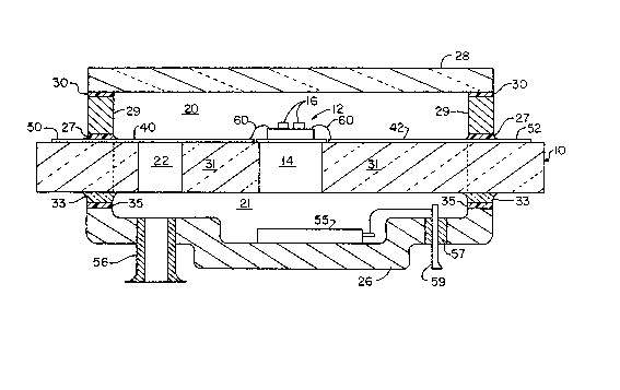
Referring to the sole: Figure, a portion of an
infrared receiver ls shown, specifically, the
: refrigerator and detector assemblies comprising the
apparatus of the present invention. This apparatus
includes a microminiature re~rigerator assembly lO,
detector assembly 12, vacuum chambers 20 and 21 coupled
together through hole 22 in assembly lO, supporting
member:s 29, 35:and 26, and optical wlndow 280
Detector subas~sembly 12 ::is~ mounted directly: onto the~
cryoge~ically cooLed portion 14~ of refrigerator ~lO.
: Dete~ctor elect:r;ical~:leads 40: ànd :42 (and otherc not
shown), and contact pads 50 and 52 (and others not
~: ; : shown), are deposited: direc~ly on the surface of
rerigerator~ 0~ uslng ~ well-know~n : ~deposltional;
tech~niques.~ : Jumper;wires 60 ~may~be~used~to~conne~ct~the:~
detector assembly 12 with~ ~he d~tector :electri~al leads~
4:0~and::~:42~ :If~ nec~ssary,; a: cold~shield,~for exampLe,:
:: , : ~ :
:: ~ "i : ' : :
- ~ :
: .: . :..... :, . , - ~ . . . .
,
~2~3~
--10--
slot shield 16, may be attached to detector assembly 12
to improve performance~
The structure of refrigerator 10 is such that region
14 of the refrigerator is at cryogenic temperatures, and
S the outer p4rtion of the disc circumfe;rence under and
around the contact pads is ~t ambient temperature. The
region in between (between region 14 and the vertical
dotted line) is the heat exchanger area which is at an
intermediate temperature.
Rings 29 and 35 are bonded to the upper and lower
surfaces of the refrigerator 10 with glass frit 27 and
33, and when firea the glass frit 27 and ~3 reflows and
forms hermetic seals between the rings 29 and 35 and the
refrlgerato~ 10. During reflow,~the glass frlt~27 ~flows
;15~ ove~r~ and around ~the electrical~ lea,ds 40 and 42, etc.,
without compromising hermeticity or ~ electrical
conductivity. The ~resulting interface~ will provide~
hermetically sealed~ electrical~; feedth~roughs for the
detector~assembly 12.~;~ The~bottom~suppor~ting~member~26 1s
20~ solde~red~to~ring 35~.~ The~member~26 i~nclude~s~a~getter 55
to~prov~i~de~continue~d~vacu~um~ pumping after seallng ~the
induced va,cuum th~ough pinch-off tube~,56.~ Member 26 also
cl`udes~a~:setter~'~eedthrough~ 7~;~for~getter~el~ectrica~
,
, ~ .. , : :
- .
~53~L~
leads 59 which, for example, may be a brazed electrical
feedthrough 57.
The optical window 28, which may be coated to form a
spectral filter and/or shaped into a lens, is attached to
ring 29 with solder or glass frit 30. In an alternate
embodiment, as shown in Figu~e 2~ a window 80 (similar to
window 28) i5 attached to flange 24 by solder or rit
82. The flange 24 is welded to ring 29 at area 84. The
inner surfaces of lower member 26 and ring 29 are
polished and coated to minimize emissivity and to reduce
radiation heat loading of re~rigerator 10.
: :
: The resulting~ package provides a~hermetically sealed
vacuum chamber 21 which, toge~ther with~ chamber 20, has no
organic~:o~r~ adhes~lve seals. The ~two ~chambers :2~0 and 21
5 ;~are~:coupled togeth~er~ through ~va:cuum ~hole 22 ~which lS
located ln refrlgerator~assembly lO~ ln a~ manner so as to~
not interf:ere with~ the electrical:leads, such as leads 40
::
and 42, o r the heat ;e~xchanger 71.~ As shown in U.~S.
Paten~ No. 4,488~,414, the:::dis:~ detecto:r assembly of the:~
20~ presen~ nventi~on~a~l:so~includes~ gas~input~ port::and;~ a:~
:gas~output~ por:t:~which ~connects~ ;to the refri~gerator~10
o~utside~ the~ vacuum~space~ so~th~at~the~ refrI~gerator w~
~: : ~ : " , . :. .; , , : .
~2~ 6
by use of an external gas supply, also not shown, cool
down the detector assembly 12.
Having described the invention, what is claimed as
new and novel and for which it is desired to obtain
Letters Pa~ent is: `
: ~ :
:;
:
:: :; :: : ,; : : ~ : :
..... . ...