Sélection de la langue

Search

Sommaire du brevet 1265945 

Énoncé de désistement de responsabilité concernant l'information provenant de tiers

Une partie des informations de ce site Web a été fournie par des sources externes. Le gouvernement du Canada n'assume aucune responsabilité concernant la précision, l'actualité ou la fiabilité des informations fournies par les sources externes. Les utilisateurs qui désirent employer cette information devraient consulter directement la source des informations. Le contenu fourni par les sources externes n'est pas assujetti aux exigences sur les langues officielles, la protection des renseignements personnels et l'accessibilité.

Disponibilité de l'Abrégé et des Revendications

L'apparition de différences dans le texte et l'image des Revendications et de l'Abrégé dépend du moment auquel le document est publié. Les textes des Revendications et de l'Abrégé sont affichés :

  • lorsque la demande peut être examinée par le public;
  • lorsque le brevet est émis (délivrance).
(12) Brevet: (11) CA 1265945
(21) Numéro de la demande: 1265945
(54) Titre français: CABLE A FIBRES OPTIQUES SENSIBLE AUX FORCES DE MICROCOURBURE
(54) Titre anglais: FIBRE OPTIC CABLE RESPONSIVE TO MICROBENDING FORCES
Statut: Durée expirée - après l'octroi
Données bibliographiques
(51) Classification internationale des brevets (CIB):
  • G01L 01/24 (2006.01)
  • G01D 05/26 (2006.01)
  • G01D 05/353 (2006.01)
  • G01L 11/02 (2006.01)
(72) Inventeurs :
  • PERSSON, SVEN ANDERS ROLAND (Suède)
(73) Titulaires :
  • TELEFONAKTIEBOLAGET LM ERICSSON
(71) Demandeurs :
  • TELEFONAKTIEBOLAGET LM ERICSSON (Suède)
(74) Agent: ERICSSON CANADA PATENT GROUP
(74) Co-agent:
(45) Délivré: 1990-02-20
(22) Date de dépôt: 1985-07-17
Licence disponible: S.O.
Cédé au domaine public: S.O.
(25) Langue des documents déposés: Anglais

Traité de coopération en matière de brevets (PCT): Non

(30) Données de priorité de la demande:
Numéro de la demande Pays / territoire Date
8403811-6 (Suède) 1984-07-20

Abrégés

Abrégé anglais


ABSTRACT OF THE DISCLOSURE
A fibre-optic cable responsive to microbending
forms part of a device for measuring pressure in accordance
with the principle of creating a periodic mechanical dis-
turbance in the fibre. The cable comprises a fibre having
a core and a core-sheath. An elongated element in the form
of a twisted filament or a twisted band extends along the
fibre, and a pirmary shield encases the fibre and the twis-
ted element.

Revendications

Note : Les revendications sont présentées dans la langue officielle dans laquelle elles ont été soumises.


THE EMBODIMENTS OF THE INVENTION IN WHICH AN EXCLUSIVE
PROPERTY OR PRIVILEGE IS CLAIMED ARE DEFINED AS FOLLOWS:
1. A fibre-optic cable responsive to microbending
forces, which includes at least one fibre which forms part of a
pressure responsive device in which a radiation source injects
light into the fibre and a sensor measures the intensity of the
light transmitted through the fibre, there being arranged between
the cable casing and the fibre at least one longitudinally
extending element for introducing a periodic disturbance having a
period length (? ) along at least a part of the fibre in response
to said pressure, wherein the element extending longitudinally
along the fibre consists of at least two twisted filaments or a
twisted band so that isolated contact surfaces are created along
the surface of the fibre, the mutual spacing of these contact
surfaces being dimensioned so as to form said period length (? )
for the periodic disturbance.
2. A cable according to claim 1, wherein said element
extends parallel with the fibre.
3. A cable according to claim 1, wherein said element
is arranged in the form of a helix around the fibre.
'

Description

Note : Les descriptions sont présentées dans la langue officielle dans laquelle elles ont été soumises.

~ s
The present invention relates to a fibre-optic cable
responsive -to microbending forces for detecting pressure by
mechanically influencing the fibre in the cable by means of a
periodic disturbance upon transmission of llght through the
fibre.
The aforesaid principle of detecting pressure by per-
mitting the pressure to act on an optic fibre made of glass or a
plastics material, so that the transmitted light is periodically
disturbed, is described in, for example, US-A.4,163,397, SE-~-410
521 and EP-A-008 2820. According to EP-~-008 2820 this periodic
disturbance can be created by winding a filament or wire heli-
cally around the optic fibre, whereafter an outer sheath is
placed around the filament and fibre structure. When light is
transm~tted through the fibre and the sheath is simultaneously
subjected to a pressure force, this pressure force tends to cause
the wire helix to flatten. In this way a series of periodic
bends in the fibre is created, each of which corresponds to half
the pitch of the helix. AS a result~ the light passing through
the fibre is attenuated, which can be detected, for example, with
the aid of a photoelectric sensor. Various ~ibre parameters
affect the attenuation of the light. In the case of a fibre
which exhibits a parabolic index profile, the periodic distur-
bance has a critical period length which produces maximum attenu-
ation. This period length can bP expressed as
~ - 2~a/(2D~1~2, where 2D = 1 - 2
~ = the periodlc length of the disturbance
nO ~ the refraction index in the centre of the core
nc = the refractive index of khe sheath
a ~ the radius o~ the fibre core.
-- 1 --
"
, : . . . , ~,
.
,, . , . -
.,:
.: , : .,
. .

~ ~ 6~ ~ ~S
One problem with the aforesaid known arrangement
according to EP-A-00~ 2~10 iS that when the diameter o~ the fila-
ment is the same as that of the fibre (d~ o.3 mm~, the filament,
because it is wound helically around the fibre, will cause the
dimensions of the cable to be undesirably large. This is unde-
sirable in the case of certain uses, ~or example, when wishing to
hide the cable incorporating the prepared fibre from view, or
when the cable is to be drawn through narrow passages. In addi-
tion, it is difficult to obtain an accurately defined disturbance
periodicity in those cases where the disturbance is determined by
the pitch of the filament helix.
An object of the present invention is to provide a
cable for detecting pressure, in which the periodic disturbance
can be obtained with simple components which afford stability to
the periodic disturbance when the cable is sub;ected to pressure.
According to the present invention there is provided a
fibre-optic cable responsive to microbending forces, which
includes at least one fibre and which forms part of a pressure
responsive device in which a radiation source injects light into
the fibre and a sensor measures the intensity of the light trans-
mitted through the fibre, there being arranged between the cable
casing and the fibre at least one longitudinally extending ele-
ment for introducing a periodic disturbance having a periodlength (~ ) along at least a part of the fibre in response to
said pressure, wherein the element extending longitudinally along
the fibre consists of at least two twisted filaments or a twisted
band so that isolated contact surfaces are created along the sur-
face of the fibre, the mutual spacing of these contact surfacesbeing dimensioned so as to form said period length ~A ) for the
periodic disturbance.
The invention will now be described in more detail, by
way of example only, with reference to the accompanylng drawings,
in which:-
~ - 2 -
~'
.
.
:
. ::

~59~i
Figure 1 illustrates a first embodiment o~ a
`
:
;~
, ~ ~
: , :
,
2a -

g~s
fibre-optic cable according to the invention;
Figure 2 illustrates a second embodiment; and
Figure 3 illus-trates a third embodirnent of the
cable according to the invention.
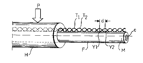
Figure 1 is a sectional view of a cable according
to the invention for detecting a pressure P applied to -the
10 ~ ~ H of the cable. The pressure P may be applied at
a point or distributed uniformly over the ~ H. The
optic fibre incorporated in the cable comprises a core C, a
core-sheath M and a surrounding layer H, the so-called pri-
mary shield, the refractive index of which is chosen to be
slightly higher than the refractive index of the core-sheath.
Located at one end of the fibre cable is a light
source, while at its other end there is arranged a photo-
sensor (not shown), light being transmitted through the
fibre F with a given mode distribution. The light source
and sensor may also be located at one and the same end of
the fibre, and a reflector arranged at the other end there-
of. An increase in the pressure P will result in greater
attenuation of the modes, due to the fact that part of the
power in each mode is coupled to other modes, inter alia
radia-tion modes, which results in reduced transmit-ted power.
This reduction can be detected in a suitable manner, with
the aid of the photosensor.
~ In order to achieve the aforesaid coupling between
-the modes, a mechanical disturbance is introduced into the
fibre. In the case of a glass fibre, this disturbance
can~be lntroduced by permitting the pressure force P to
act~-~upon the primary ~ H (Figure 1), while in the case
of a pl~astics fibre it is sufficient for the pressure force
P to act directly on the core-sheath M. The disturbance
~ - 3 -
. ~ ~
,' : , ` :: , `. , :~ : .~ '
;

~%~
is intended to create periodlc deformation of the fibre. This
disturbance is created in the fibre incorporated in the cable
according to Figure l with the aid of an elonga-ted deformed fila-
ment-element in the form of a double-filament structure compris-
ing two twisted filaments Tl and T2. The filaments are twistedrelatively firmly, so as not to be displaced axially in relation
to one another to any appreciable extent when the pressure P is
applied to the layer ~I forming the primary shield. The double
filament struc-ture Tl,T2 introduces small isolated contact sur-
faces Yl,Y2 against the core-sheath C, which are repeated at a
given periodicity d. Accordingly, optimal damping of light
through the fibre core is obtained with a fibre of given dimen-
sion, namely when d = ~ = 2~ a/(2D)l/2. In this embodiment, the
double-filament structure Tl,T2 is placed straight along the
fibre and parallel therewith.
In the embodiment o~ the cable illustrated in Figure 2,
the double-filament structure Tl,T2 comprising said twisted fila-
ments is wound helically around the fibre F. As with the Figure
l embodiment, there are obtained small contact surfaces Yl,~2
with given periods d along the whole length of the filament
structure. In this embodiment the pressure force P may be
directed towards the surrounding core-sheath M from various
dlrections around the fibre, since the given deformation of the
filament structure Tl,T2 ensures that a pressure ~orce is exerted
against the core-sheath M.
The dimension of the filament structure Tl,T2, i.e. the
spacing between the la~er H and the fibre F should be of the same
order as the cross-sectional dimension of the fibre. This
enables the filament structure Tl,T2 to be wound at a greater
pitch around the fibre F, and the critical distance d A will
not be contingent o~ the pitch of the heli~.

~659A5
In the embodiment illustrated in Figure 3, the
longitudinal deforming element cornprises a rigid or an elas-
tic twisted band B, which is wound around the fibre. In
this way isclated contact surfaces Yl, Y2 are formed at the
locations a-t which the band abuts the core-sheath M, these
isola-ted surfaces producing the periodic dis-turbance (d =~).
The cable construction according to the present -
invention distinguishes from the prior art constructions
in that the elongated element extended longi-tudinally around
the optical fibre is deformed initially, from the start, so
that a periodic distrubance is able to occur upon contact
of said element with the fibre. The advantage gained hereby
resides in that greater freedom is obtained in disposing
the disturbance-creating element between the cable casing
and the fibre, and therewith greater possibli-ty of reducing
the cross-sectional dimensions of the whole cable, when it
is to be used as a pressure sensing device.
`
:
~ : '
35 ~ ~ ~
~: .,:
- . ~. . :
,. . ~ .. . ..
:

Dessin représentatif
Une figure unique qui représente un dessin illustrant l'invention.
États administratifs

2024-08-01 : Dans le cadre de la transition vers les Brevets de nouvelle génération (BNG), la base de données sur les brevets canadiens (BDBC) contient désormais un Historique d'événement plus détaillé, qui reproduit le Journal des événements de notre nouvelle solution interne.

Veuillez noter que les événements débutant par « Inactive : » se réfèrent à des événements qui ne sont plus utilisés dans notre nouvelle solution interne.

Pour une meilleure compréhension de l'état de la demande ou brevet qui figure sur cette page, la rubrique Mise en garde , et les descriptions de Brevet , Historique d'événement , Taxes périodiques et Historique des paiements devraient être consultées.

Historique d'événement

Description Date
Inactive : Périmé (brevet sous l'ancienne loi) date de péremption possible la plus tardive 2007-02-20
Inactive : TME en retard traitée 2006-04-24
Inactive : CIB de MCD 2006-03-11
Lettre envoyée 2006-02-20
Exigences relatives à la révocation de la nomination d'un agent - jugée conforme 2004-11-22
Exigences relatives à la nomination d'un agent - jugée conforme 2004-11-22
Inactive : Lettre officielle 2004-11-19
Accordé par délivrance 1990-02-20

Historique d'abandonnement

Il n'y a pas d'historique d'abandonnement

Titulaires au dossier

Les titulaires actuels et antérieures au dossier sont affichés en ordre alphabétique.

Titulaires actuels au dossier
TELEFONAKTIEBOLAGET LM ERICSSON
Titulaires antérieures au dossier
SVEN ANDERS ROLAND PERSSON
Les propriétaires antérieurs qui ne figurent pas dans la liste des « Propriétaires au dossier » apparaîtront dans d'autres documents au dossier.
Documents

Pour visionner les fichiers sélectionnés, entrer le code reCAPTCHA :


Pour visualiser une image, cliquer sur un lien dans la colonne description du document. Pour télécharger l'image (les images), cliquer l'une ou plusieurs cases à cocher dans la première colonne et ensuite cliquer sur le bouton "Télécharger sélection en format PDF (archive Zip)" ou le bouton "Télécharger sélection (en un fichier PDF fusionné)".

Liste des documents de brevet publiés et non publiés sur la BDBC .

Si vous avez des difficultés à accéder au contenu, veuillez communiquer avec le Centre de services à la clientèle au 1-866-997-1936, ou envoyer un courriel au Centre de service à la clientèle de l'OPIC.


Description du
Document 
Date
(aaaa-mm-jj) 
Nombre de pages   Taille de l'image (Ko) 
Abrégé 1993-09-17 1 23
Revendications 1993-09-17 1 33
Dessins 1993-09-17 1 29
Description 1993-09-17 6 235
Dessin représentatif 2002-02-18 1 9
Avis concernant la taxe de maintien 2006-04-17 1 172
Quittance d'un paiement en retard 2006-05-08 1 165
Correspondance 2004-11-18 1 8
Correspondance 2004-11-21 1 13
Taxes 2006-04-23 1 29
Taxes 1997-01-26 1 61
Taxes 1996-01-21 1 59
Taxes 1995-01-15 1 58
Taxes 1994-01-24 1 43
Taxes 1992-12-20 1 36
Taxes 1992-01-02 1 37