Note : Les descriptions sont présentées dans la langue officielle dans laquelle elles ont été soumises.
~26~i~6~3
SUPPORT SHAFT FOR WINDING/UNWINDING SHEETS
This invention relates to a support shaft for
winding/unwinding sheets, e.g., plastic films, metal foils
or thin sheets, etc.
The inventor has previously proposed a drive shaft
for taking up sheets, which comprises a shaft, -the outer
periphery of which is formed with a plurality of inclined
grooves circumferentially spaced apart and having the
bottoms thereof inclined in the circumferential direction,
rollers each accommodated in the inclined grooves so as to
be capable of rolling in the longitudinal direction
thereof, a plurality of sector-like members arranged side
by side to surround the shaft inclusive of -the rollers,
and expansible retaining members retaining the sector-like
members such that the sector-like members can be shifted
radially outwardly. The sector-like members constitute
the shaft, on which a sheet to be taken up is directly
wound one or a plurality of turns, or on which a core for
taking up a sheet thereon is fitted. The shaft is then
rotated in a direction to cause the rollers to roll along
the inclined grooves toward shallow portions thereof and
thus project therefrom, thereby causing a radially outward
shift of the sector-like members into tight engagement
with the inner periphery of the wound sheet section or
core for rotation in unison therewith so that the sheet i9
taken up.
This drive shaft has no problem so far as it is
rotated in unison with the wound sheet section or core for
taking up the sheet. However, since a plurality of
sector-like members are arranged side by side to surround
the inner shaft and the rollers, troublesome steps are
re~uired for its machining and assembly. More
specifically, a set of sector-like members is prepared by
preparing a ring-like material finished to a desired size
~LZ~64~
using a lathe or the like and then radially precision-
cutting the ring-like material into equal sector-like
divisions with very narrow cutting gaps between the
adjacent divisions. It requires a great deal of care on
the part of the worker to accurately fix the ring-like
member or sector-like divisions firmly to a vise or the
like in a cutting posture and in a state such that the
member or divisions will not be deformed. Further, it is
necessary to machine the sector-like divisions to form
recesses for accommodating the retaining members therein.
Furthermore, the expansible retaining members have to be
accommodated in the recesses formed in the machined
sector-like divisions, i.e., sector-like members, after
setting these members on the outer periphery of the shaft.
Where piano wires are used as the expansible retaining
members to be accommodated in the recesses formed in the
sector-like members on either inner-or outer sides
thereof, for example, some of the piano wires or some of
the sector-like members are liable to detach during the
work of retaining all sector-like members. Therefore, the
assembling operation is very troublesome and time-
consuming. Further, the retaining members are liable to
detach during rotation of the drive shaft. Where the
retaining members are bonded to the sector-like members,
the bonding work has to be done very carefully lest the
bonded retaining members should be detached. Furthermore,
piano wires or steel springs used as the retaining members
lead to machining difficulties although they can ensure
excellent durability. Further, with the conventional
continuoùsly straight surface or curved inclined surface
having no corrugation it is difficult to temporarily lock
the wound sheet or core which has already been set in
position on the drive shaft.
An object of the invention is to provide a support
shaft which can be manufactured by easy machining and
~6~6~
- 3 ~
assembly and can reliably lock the sheet winding section
or core because it comes into contact at its entire
circumference with the inner periphery of the section or
core durin~ its rotatlon to form the section or core
substantially in the shape of a true circle, whereby a
sheet can be wound on or unwound from the section or core.
Accordingly, one aspect of the invention
prov~des a support shaft for friction windlng/unwinding
sheets, the support shaft comprising: (a) a drive shaft,
(b) a plurality of rinys ~uxtaposedly and rotatably
fitted on the drive shaft, each one of the plurality of
rings having the upper periphery thereof formed with a
plurality of circumferentially inclined grooves
circumferentially spaced apart, each one of the inclined
grooves having an inclined bottom, (c) torque
transmitting means for transmitting torque from the drlve
shaft to each one of the plurality o~ rings, (d) rollers
accommodated ln the inclined yrooves for rolling therein
from a deep portion thereof toward a shallow portion
thereof to progressively increase the extent of pro~ection
therefrom with a rotation of the plurality of rings, (e)
space holding means provided near the plurality of rings
for holding the rollers spaced apart in the
circumferential direction of the plurality of rings in
engagement of the rollers during rolling thereof, and (f~
a plurality of outer rings, each one of the plurality of
outer rings having a gap and at least one flange
pro~ecting therefrom radially inwardly along an end face
of a corresponding one of the rollers, each one of the
plurality of outer rlng~ being fitted on a corresponding
one of the plurality of rings to ~urround the outer
~urfaces of the associated ones of the rollers and being
capable of being expanded by the urging force of the
rollers.
Another a~pect of the invention provides ln a
~haft for windiny/unwinding sheets, in which a ~rive shaft
has the outer periphery thereof formed with a plurality of
circumferentially inclined grooves circumferentially
~2t~6~6~)
- 3a -
spaced apart and having an inclined bottom and rollers are
accommodated in respective ones of the inclined yroove~
for rolling therein from a deep portion toward a ahallow
portion thereof to progressively increase the extent of
pro~ection thereof with a rotation of the sha~t, thereby
effecting the winding/unwinding of sheets, the improvement
of the shaft wherein the outer surface o~ the rollers i8
surrounded by an outer ring having a ~ap and also ha~ing
radially inwardly pro~ecting flanges provided on opposite
end face~ of each one of the rollers.
With the above construction of the support
shaft, the rollers caused to roll along the inclined
grooves in the longitudinal direction thereof from the
deep portion toward the shallow portion thereof to
1~ progressively increase the e~tent of their pro~ection
therefrom with the rotation of the shaft, urge and cause
e~pansion of the outer ring with the width of the gap
increased, thereby bringing the outer ring into tight
engagement either with a sheet winding section formed by
winding a sheet one or more turns on the outer ring or
with a core fitted t~ereon.
Slnce the rollers are surrounded by the outer
ring with a gap, the support shaft according to the
invention can be readily assembled and can operate
reliably without being disassembled during operation.
Further, since the core can precisely be locked by the
outer ring with the inner periphery of the core brought
into contact with the
.". .. .. . , ., ,. . s
~26~60
entire circumference of the outer ring, there is no fear
of the core being made eccentric. Therefore, the
invention can advantageously be utilized particularly in
winding a sheet of a narrow width or winding a sheet into
a large-diameter roll, thus completely solving the
conventional problem of production of inferior goods
having their end faces out of alignment due to the
eccentricity of the core.
The above and other objects and features of the
invention will become more apparent from the following
description with reference to the accompanying drawings in
which:
Figure 1 is a front view, partly in section,
showing a first embodiment of the support shaft according
to the invention;
Figure 2 is a fragmentary enlarged-scale side view,
partly in section, showing an essential part of the
support shaft shown in Figure l;
Figure 3 is a fragmentary enlarged-scale front
view, partly in section, showing an essential part of the
support shaft shown in Figure l;
Figure 4 is an exploded front view, partly in
section, showing the part shown in Figure 3;
Figure 5 is a view similar to Figure ~ but showing
a different embodiment of the support shaft according to
the invention;
Figure 6 is a front view, partly in section,
showing a further embodiment of the support shaft
according to the invention;
Figure 7 is a side view, partly in section, showing
the support shaft shown in Figure 6;
Figure 8 is a front view, partly in section,
showing a further embodiment of the support shaft
according to the invention;
Figure 9 is a side view, partly in section, showing
;~266460
the support shaft shown in Figure 8;
Figure 10 is a fragmentary enlarged-scale side
sectional view showing a further embodiment of the support
shaft according to the invention;
Figure 11 is a fragmentary enlarged-scale
elevational sectional view showing the support shaft shown
in Figure 10;
Figure 12 is a front view, partly in section,
showing a further embodiment of the invention;
Figure 13 is a fragmentary enlarged-scale side
sectional view showing the support shaft shown in Figure
12;
Figure 14 is a view similar to Figure 13 but
showing a modification of inclined grooves of the support
shaft shown in Figure 13;
Figure 15 is a view similar to Figure 13 but
showing another modification of the inclined grooves of
the support shaft shown in Figure 13;
Figure 16 is a view similar to Figure 13 but
showing a further modification of the inclined grooves of
the support shaft shown in Figure 13;
Figure 17 is a view similar to Figure 13 but
showing a still further modification of the inclined
grooves of the support shaft shown in Figure 13;
Figure 18 is a view similar to Figure 13 but
showing a further embodiment of the support shaft
according to the invention;
Figure 19 is a front view, partly in section,
showing a further embodiment of the support shaft
according to the invention;
Figure 20 is a side sectional view taken along line
XX-XX in Figure 19;
Figure 21 is a fragmentary side view, partly in
section, showing a further embodiment of the support shaft
according to the invention;
;~L2664&i~
Figure 22 is a fragmentary front view, partly in
section, showing the support shaft shown in Figure 21;
Figure 23 is a fragmentary side sectional view,
partly in section, showing a further embodiment of the
support shaft according to the invention;
Figure 24 is a fragmentary front view, partly in
section, showing the support shaft shown in Figure 23;
Figure 25 is a plan view showing the support shaft
shown in Figure 23;
Figure 26 is a fragmentary enlarged-scale sectional
front view showing a further embodiment of the support
shaft according to the invention;
Figure 27 is a side sectional view taken along line
XXVII-XXVII in Figure 26;
Figure 28 is an explanatory view of one example of
how to support a core with the support shaft according to
the invention;
Figure 29 is an explanatory view of another example
showing how to support a core with the support shaft
according to the invention; and
Figure 30 is a front view, partly in section,
showing a still further embodiment of the support shaft
according to the invention.
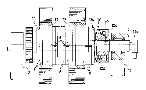
Figures l to 4 show a first embodiment of the
support device according to the invention. Reference
numeral l designates a rotary shaft detachably supported
between a pair of frames or arms 2 of a sheet winding
machine. The shaft 1 has a gear or a chain wheel which is
secured at one end of the shaft 1 and through which the
rotation of the shaft 1 is transmitted. A plurality of
juxtaposed thin transmission wheels 3 keyed together by
keys la are rotatably mounted on the outer periphery of
the shaft 1 substantially over the entire length thereof
except for the opposite ends thereof rotatably supported
by the arms 2. A ring 5 is fitted on the outer periphery
.~266~6~
-- 7
of each of the transmission wheels 3. The ring 5 has a
plurality of, e.g., six, inclined grooves 4 uniformly
spaced apart in the circumferential direction. Each
inclined groove 4 has an inclined bottom. A roller 6 is
partly accom~odated in each of the inclined grooves 4.
The inclined groove 4 is formed in the outer
periphery of the ring 5 such that it extends in the
circumferential direction. In this embodiment, the bottom
of the groove 4 becomes progressively deeper from one end
4a toward the other end 4b. The bottom of the groove 4
need not be a flat surface as illustrated so long as its
depth increases from one end toward the other end. For
example, it may be curved in a convex or concave form, or
it may be a succession of two or more flat surfaces having
different inclination angles.
The roller 6 which is partly accommodated in the
inclined groove 4 of the ring 5 is retained by a roller
retainer-ring 7 fitted on the outer periphery of the ring
5. An outer ring 8 with a gap 9 is fitted on the outer
periphery of the roller retainer ring 7.
The roller retainer ring 7 has pockets 7a which
correspond in number to the number of the carried rollers
and are uniformly spaced apart in the circumferential
direction. Thus, the rollers 6 are held at a fixed
distance from one another at all times. Each roller 6
projects to a maximum extent from the pocket 7a of the
ring 7 when it is located at the shallow end 4a of the
inclined groove 4. The extent of projection of the roller
6 from the outer periphery of the roller retainer ring 7
is reduced progressively as the roller 6 rolls along the
inclined groove 4 toward the deep end 4b. The outer ring
8 is axpanded or contracted with the rolling of the
rollers along the grooves. The gap 9 of the outer ring 8
thus is narrowest when the roller 6 is at the deep end 4b
of the inclined groove 4. The outer ring 8 is made of an
.. ...
~;26646~
elastic materialt e.g., soft steel or plastic, so that it
can contract by itself after being expanded. However, to
ensure contraction of the outer ring 8, an elastically
expansible me~ber 10 may be fitted in a circumferential
annular groove formed in the outer periphery of the outer
ring. Further, the outer ring 8 may have a knurled outer
peripheral surface to provide for increased friction and
increased core-holding force. The elastically expansible
member 10 may be a band loop made of tenacious elastomer
or a rounded piano wire. However, if a sufficiently
strong contractive force of the outer ring 8 is selected,
the attachment of the outer ring to the core or the like
may be automatically released with the rollers 6 forcibly
returned to the deep ends 4b of the inclined grooves 4 by
the contractive force of the outer ring as soon as the
rotation of the rotary shaft 1 is stopped.
In this embodiment, the transmission wheel 3, ring
5, roller retainer ring 7 carrying a plurality of rollers
6 and outer ring 8 constitute a core holder element. A
plurality of these core holder elements are juxtaposedly
fitted on the shaft 1 substantially over the entire length
thereof except for the opposite ends as noted above. The
juxtaposed core holder elements fitted on the shaft 1 are
clamped by a collar 11 securely fitted on the shaft and an
urging unit 12 for urging all core holder elements toward
the collar 11 with an adequate force provided by a spring
or pressurized fluid. Each ring 5 is rotatable with its
inner periphery held in frictional contact with the
corresponding transmission wheel 3 and a transmission
wheel axially adjacent thereto. The rollers 6, roller
retainer rings 7 and outer rings 8 are arranged such that
a slight gap is left between axially adjacent ones and
also between the terminal one and the collar 11.
To this end, the ring 5 is made slightly thicker
than any of the transmission wheel 3, the roller retainer
:1266'~60
g
ring 7 and the outer ring 8. The transmission wheel 3 has
an outer annular peripheral projection 3', and the ring 5
has an inner annular peripheral depression 5' fitting on
the projection 3'. The inner portion of the ring 5 other
than the inner annular peripheral depression 5' is clamped
between the outer annular peripheral projection 3' of the
transmission wheel 3 and the outer annular peripheral
projection 3' of the adjacent transmission wheel 3.
The transmission wheel 3 is made of a plastic
material which may or may not contain reinforcing fibers
or phosphor bronze or oil-impregnated metal. The ring 5,
rollers 6 and roller retainer ring 7 are made of a metal,
and the outer ring 8 is made of either a plastic material
or metal. The materials noted above are only examples
and, of course, may be suitably altered.
In this embodiment, the urging unit 12 includes a
movable collar 12a fitted for axial movement on the shaft
1, an annular cylinder 12c secured to the shaft 1 and
provided with an annular piston 12b and a coil spring 12d
provided between the piston 12b and the movable collar
12a. The corresponding end of the shaft 1 is provided
with a rotary joint 12e. Fluid pressure is applied
through the rotary joint 12e and a port into the annular
cylinder 12c, so that the juxtaposed core holder elements
are urged against the collar 11 by both the fluid pressure
and the spring force of the coil spring 12d. Of course it
is possible to utilize only one or the other of the spring
force and the fluid pressure.
On the juxtaposed array of core holder elements
there may be fitted a single core substantially having a
width equal to the axial length of the array or a
plurality of cores 13 having a small width. Instead of
using a core for taking up a sheet thereon, it is possible
to wind an end portion of a sheet once or several turns on
the corresponding outer ring 8 and then secure the wound
:iL2~ S~
- 10 -
sheet by an adhesive or adhesive tape to form a sheet
winding section. As a further alternative, an end portion
of a sheet may be wound on a belt or a group of rollers
surrounding the outer periphery of the corresponding outer
ring.
When using the core 13, after fitting the core, the
ends of the shaft 1 are mounted between the pair of arms 2
of the winder, and the leading end of the sheet is
attached by an adhesive tape or the like to the outer
periphery of the core. In the case of forming a sheet
winding section or directly winding a sheet, these
operations must be done after mounting the ends of the
shaft between the arms 2. Afterwards, the shaft is driven
for clockwise rotation in Figure 2 to take up the sheet.
The transmission wheel 3 is rotated in unison with the
shaft 1, and the ring 5 begins to rotate in the same
direction due to the frictional relationship with the
transmission wheel 3. At this time, the rollers 6 which
have been at the respective deep ends 4b of the inclined
grooves 4 of the ring 5 begin to roll along the inclined
grooves toward the shallow ends 4a thereof due to the
friction with the outer ring 8 produced by the tension in
the sheet, thus progressively projecting from the inclined
grooves. The outer ring 8 surrounding the roller retainer
ring 7 is urged radially outwardly by the rollers 6, which
roll along the inclined grooves toward the shallow ends
thereof and are progressively projected from the inclined
grooves, so that the gap 9 becomes wider and wider until
the outer periphery of the outer ring 8 is in tight
engagement with the inner periphery of the core 13 or the
sheet winding section. Once this tight engagement is
attained, the outer ring 8 is rotated in unison with the
ring 5 and also with the core or the sheet winding section
so that the sheet is taken up thereon. Since the rollers
are supported by the retainer ring 7 and roll on the
lZ6~0
-- 11
inclined grooves 4 from the deep ends 4b to the shallow
ends 4a, the outer ring 8 is enlarged in diameter to have
its entire circumference engaged with the inner periphery
of the core, with the result that the core is not made
eccentric.
In this state, the outer ring of the core holder
element with the core or sheet winding section thereon is
in tight engagement with the inner periphery of the core
or sheet winding section, and the rollers urging the outer
ring radially outwardly are located at positions
immediately adjacent to the shallow ends of the inclined
grooves.
The outer diameter of the outer rings 8, when the
rollers 6 are at the shallow ends 4a of inclined grooves
4, may be set to be greater by 10 mm, for instance, than
their outer diameter assumed when the rollers 6 are at the
deep ends 4b of the inclined grooves 4. In this case, even
though the inner diameter of the cores or sheet winding
sections is greater by less than 10 mm than the outer
diameter of the outer rings 8 when the rollers 6 are at
the deep ends 4b of the inclined grooves 4, the cores or
the sheet winding sections may be coaxially supported on
the drive shaft and driven smoothly for rotation.
When a predetermined length or amount of sheet has
been taken up on the core 13 or sheet winding section, the
rotation is stopped, and the shaft is taken out from
between the arms. Then, the obtained roll of sheet is
turned together with the core or sheet winding section
while gripping the shaft so that the rollers are caused to
roll toward the deep ends of the inclined grooves. At
this time, the outer ring 8 is initially rotated in unison
with the core or sheet winding section, causing the
rollers 6 to roll along the inclined grooves toward the
deep ends thereof. As the rollers approach the deep ends
of the inclined grooves, the extent of their projection
:~2~460
- 12
from the inclined grooves is progressively reduced.
Consequently, the outer ring 8 is urged radially inwardly
by its own elasticity and also by the contracting force of
the elastically expansible members to be separated from
the inner periphery of the core or sheet winding section.
In this state, the shaft may be withdrawn from the
core or sheet winding section.
In this embodiment a plurality of narrow
transmission wheels, rings, roller retainer rings and
outer rings are juxtaposedly fitted on the shaft such that
the transmission wheels are rotated in unison with the
cshaft while the rings are adapted to be rotated by
friction in the same direction as the transmission wheels.
Thus, a core or sheet winding section having an increased
width can be supported on an increased number of outer
rings, that is, the core or sheet winding section can be
rotated for rotation with a predetermined take-up torque
according to the width of the core or sheet winding
section.
In addition, the rollers 6 in contact with the
outer ring 8 are uniformly spaced apart by the roller
retainer ring 7, which is suitable for taking up a sheet
at a high speed with less eccentricity.
Further, since in this embodiment the transmission
wheels 3, rings 5, roller retainer rings 7 and outer rings
8 have small thickness, the pockets 7a and the inclined
grooves 4 are open on the same side (Figure 4), while each
outer ring 8 has a radially inwardly projecting flange 8'
provided on one side thereof and adapted to be in
frictional contact with the outer periphery of roller
retainer ring 7 when the rollers 6 are brought to the deep
ends 4b of the inclined grooves 4.
Figure 5 shows a second embodiment of the
invention. In this instance, the opposite sides of the
inclined groove 4 and those of the pocket 7a are closed by
opposed walls 4' and 7', respectively, and each outer ring
i6~6~)
- 13
8 has a pair of radially inwardly projecting flanges 8'
provided on both sides. In this case, the core holder
element consisting of the transmission wheel 3, ring 5
with the grooves 4, a plurality of rollers 6, roller
retainer ring 7 and outer ring 8 may be provided as a unit
to facilitate its mounting on the shaft and removal
therefrom for repair. Further, the roller retainer ring 7
consists of two ring halves which are coupled together in
the axial direction with bolts or by welding. The pockets
are defined between the two ring halves. This arrangement
facilitates manufacture compared with forming pockets in a
single member~ -
Figures 6 and 7 show a third embodiment of thesupport shaft. This embodiment is the same as the first
embodiment so far as a plurality of core holder elements
each consisting of the thin ring 5, roller retainer ring 7
and outer ring 8 are juxtaposedly fitted on the shaft 1
over an axially inte~mediate portion thereof for driving
cores or sheet winding sections with take-up torque
proportional to the width of the cores or sheet winding
sections. The third embodiment is different from the
first embodiment in that it does not use any transmission
wheel but the ring 5 with grooves 4 is directly fitted on
the shaft 1. In addition, the shaft 1 is hollow and
defines an inner space 20. The cylindrical wall of the
inner space 20 is formed with a plurality of (three in
this embodiment) circumferentially uniformly spaced-apart
through holes 2 facing the inner periphery of the ring 5.
Plungers 14 penetrate the through holes 21 for movement in
the radial directions. An expansible tube 15 closed at
one end is accommodated in the inner space 20 of the shaft
1. The tube 15 is expansible by fluid pressure introduced
into it through a port provided in the shaft. With
expansion of the tube 15, the plungers 14 are pushed
radially outwardly, causing the outer end of the plungers
i64SO
- 14
to push the inner periphery of the ring 5 to cause
rotation of the ring 5 in the same direction as the
rotation of the shaft due to friction with the plungers.
Slip rings 5a made of phosphor bronze, oil-impregnated
metal, plastic containing carbon fiber, etc. are fitted in
the inner periphery of the ring 5 so -that the inner
periphery of the ring can smoothly slip over the outer
periphery of the shaft. The ring 5 has inclined grooves
4, each of which has circumferentially opposite shallow
portions 4a and a deep portion 4b. This inclined groove
may be formed by removing an outer peripheral portion of
the ring 5 along a plane. When cores or the like are not
mounted, the roller 6 is held in the central deep portion
of the inclined groove by the contractive force of the
outer ring as in the first embodiment. In this embodiment
a magnet piece 16 is provided at the bottom of the deep
portion 4b of the inclined groove 4 to hold the roller 6
in the deep portion 4b. In this embodiment, when the
shaft 1 is rotated in either direction to take up a sheet,
the rollers on the inner periphery of the outer ring with
a core or sheet winding section fitted thereon are caused
to roll along the inclined grooves toward the shallow end
portion against the attraction force of the magnets and
the contractive force of the outer ring, thus urging the
outer ring radially outwardly into tight engagement with
the inner periphery of the core or sheet winding section.
When the shaft and the sheet roll formed thereon are
rotated relative to each other to withdraw the shaft from
the core or sheet winding section, the engagement between
the core or sheet winding section and the outer ring is
released, whereupon the rollers are quickly returned to
the deep portions of the inclined grooves by the
contractive force of the outer ring and attractive forces
of the magnets. The rollers are held in the deep portions
of the inclineclgrooves by the magnet pieces so that they
o
- 15
are not detached even when the outer ring is removed.
In this embodiment, the urging unit of the first
embodiment is unnecessary, so that the juxtaposed core
holder elements may be clamped between two collars 11
secured to the shaft.
Figures 8 and 9 show a fourth embodiment of the
support shaft according to the invention. In this
embodiment, as in the preceding third embodiment, an
expansible tube 15 is accommodated in the inner space 20
of the shaft 1, rings 5 are fitted directly on the shaft
1, and plungers 14 penetrate holes formed in the
cylindrical wall of the shaft for radially outward
movement with the expansion of the tube 15 so as to cause
the rings 5 to be rotated in the same direction as the
shaft 1 due to friction with the plungers 14.
In this embodiment, the rings 5 are provided in
pairs. The individual pairs of rings 5 are partitioned
with respect to one ano-ther by annular partitioning disks
17 rotated in unison with the shaft 1, the rings 5, the
roller retainer rings 7 and the outer rings 8. The two
rings 5 in each pair have their facing sides formed with
inclined surfaces 18 formed adjacent to the inner
periphery. Each plunger 14 has a wedge-like outer end 14'
having opposite inclined side surfaces fitting the
inclined surfaces 18 of the pair rings. When the plunger
14 is pushed radially outwardly with the expansion of the
tube 15, the wedge-like end 14' wedges between the
associated inclined surfaces 18. Thus, each ring 5 is
rotated in the same direction as the shaft by friction.
In this embodiment the inclined grooves in the rings each
have a shallow end 4a and a deep end 4b as in the first
embodiment, but a magnet piece 16 is buried under the
bottom of the deep end of each inclined groove as in the
second embodiment. Eurther, the opposite sides of the
inclined grooves 4 are closed by opposed side walls, and
.~26~
- 16
each outer ring 8 has radially inwardly projecting flanges
8' provided on the opposite sides. Further, the outer
periphery of the shaft 1 is provided with axial grooves 19
provided at intermediate positions between
circumferentially adjacent plungers 14, and the annular
partitioning disks 17 have radially inward projections 17'
which are received in the grooves 19 so that the
partitioning disks 17 are rotated in unison with the shaft
1. The core holder elements consisting of the rings 5,
the rollers 6, the roller retainer rings 7 and the outer
rings 8 fitted together with the annular partitioning
disks 17 on the intermediate portions of the shaft 1, are
clamped between two collars 11 secured to the shaft 1.
Thus, they are axially immovable. ~owever, the annular
partitioning disks 17 may be axially immovably mounted on
the shaft, if necessary.
Figures 10 and 11 show a fifth embodiment of the
support shaft according to the invention. In this
embodiment, plungers 14 penetrating circumferentially
arranged through holes 21 formed in the cylindrical wall
of the shaft 1 are each provided in a radially inner
portion with a piston 22 having substantially the same
diameter as the hole 21. The through holes 21 serve as
cylinders, and the piston in each hole 21 is pushed by
compressed air supplied into the inner space of the shaft
1. As a result, the rings 5 which are loosely fitted on
the outer periphery of the shaft 1 are urged at the inner
periphery by the outer end of the plungers 14 to be
rotated in unison with the shaft 1.
In this embodiment, each core holder element
consists of a ring 5 with inclined grooves 4 formed in its
outer periphery, a roller retainer ring 7 fitted on the
ring 5, rollers 6 carried by the roller retainer ring 7
and accommodated in the inclined grooves 4 and an outer
ring 8 fitted on the outer periphery of the roller
.~6~460
retainer ring 7. With the rotation of the shaft 1, each
roller 6 is moved along the inclined groove 4 toward the
shallow portion thereof to increase the extent of its
projection. The outer ring 8 thus is expanded to urge and
secure the core 13. The pressure of pressurized fluid
supplied into the shaft inner space 20 may be controlled
to control the urging force, i.e., frictional force,
between the plungers 14 and the rings 5 so as to control
the torque transmitted from the shaft 1 to the rings 5
with the driving of the shaft.
When replacing a worn-out plunger 14, the rings 5
are axially shifted until the worn-out plunger to be
replaced appears, and then the retainer ring 23 provided
at an end of the through hole 21 is taken out. Then, the
plunger can be taken out, and a new plunger can be
inserted.
Figures 12 and 13 show a sixth embodiment of the
support shaft according to the invention. In this
embodiment, the outer periphery of a ring 5 is formed with
inclined grooves 4. As shown in Figure 13, each of the
grooves 4 has a deep portion 4b,an intermediate portion 4c
and a shallow-portion 4a so that the bottom thereof has
inclined surfaces in two stages. Therefore, the core can
be temporarily and completely locked when the roller 6 is
located at the intermediate portion 4c and at the shallow
portion 4a of the groove 4 respectively.
Figure 14 shows an embodiment in which each
inclined groove 4 formed in the ring 5 has a recess in an
intermediate portion thereof between the shallow portion
4a and the deep portion 4b. When the roller 6 rolls along
the inclined groove 4 from the deep portion toward the
shallow portion with the relative rotation of the ring 5
and the outer ring 8, it is received in the recess,
whereby the outer ring 8 which has been slightly expanded
assumes a temporarily locked state in contact with a core
~z~
on its outer periphery. With further rotation of the ring
5, the roller 6 escapes the recess and rolls toward the
shallow portion, thus further expanding the outer ring 8
so that the outer ring is ultimately rotated in unison
with the core.
Figure 15 shows an embodiment in which the outer
periphery of the ring 5 is formed with inclined grooves 4
having a convexly arcuate sectional profile close to the
arc of the outer periphery. The roller 6 is partly
received in the inclined groove 4 and retained by a roller
retainer ring 7 fitted on the ring 5. An outer ring 8
with a gap 9 is fitted on the roller retainer ring 7.
With this structure, even when the roll of wound sheet is
heavy, a force is exerted in a direction close to
perpendicular, so that no substantial rewinding force is
exerted.
Figure 16 shows an embodiment in which the outer
periphery of the ring 5 is formed with a plurality of
arcuate grooves 4, instead of inclined grooves,
continuously in the circumferential direction.
Figure 17 shows an embodiment in which the outer
periphery of the ring 5 is provided with a plurality of
angular grooves 4 continuously in the circumferential
direction. With the angular grooves 4, the extent of
projection of the roller 6 from the groove 4 can be
increased over that in the case of the aforesaid arcuate
grooves. In addition, with the provision of an increased
number of rollers, their area of contact with the outer
ring 8 is increased. Therefore, when the weight of the
sheet roll increases or when a heavy metal sheet is taken
up, a reliable lock action can be obtained, which is very
effective.
Figure 18 shows an embodiment in which an outer
ring 8 has liners 28 provided at end portions defining a
gap 9. When the outer ring 8 is spread with rolling of
6~i0
-- 19 -
the rollers 6 toward the shallow portions of the grooves,
heavy load is exerted on the ends of the outer ring 8 with
the gap 9. As a result, the ends of the outer ring are
subject to a force tending to bend them toward the outer
periphery of the roller retainer ring 7. However, the
actual bending of the ends of the outer ring is prevented
by the liners 28. The liners 28 may be secured by means
of screws 29. The liners may be replaced with rollers,
balls, etc. in view of little difference in function and
effect among them. Further, the outer periphery of the
roller retainer ring 7 is provided with a groove 30 which
serves to maintain circularity of the outer ring 8 and
control the position of the gap 9 of the outer ring 8
between the rollers 6.
When winding or unwinding a metal sheet or taking
up a sheet into a large diameter roll, heavy load is
inevitably exerted to result in bending of the end
portions of the outer ring toward the outer periphery of
the roller retainer ring 7. As a result, a deviation from
true circularity results, leading to a swing of the roll
being wound into a complete roll or disalignment of the
end faces of the roll. This is prevented by the liners.
All of the above embodiments of the support shaft
is of the type which penetrates the cores or sheet winding
sections and is mounted at its opposite ends in a pair of
frames or arms of a winder. These embodiments, however,
are by no means limitative, and the invention is also
applicable to a cup-shaped support shaft which consists of
a pair of support shafts each detachably mounted in each
of pair arms of a winder and inserted to a shal7Ow extent
into a core or a sheet winding section.
Figures 19 and 20 illustrate an embodiment of the
invention applied to a cup-shaped support shaft. In this
instance, a considerably longer ring 5 with an outer
flange 5b provided at one end is keyed by a key la to the
1~664~2o
outer perphery of the shaft 1. An elongate roller
retainer ring 7 carrying elongate rollers 6 is fitted on
the ring 5. An outer ring 8 with a gap 9 is fitted on the
roller retainer ring 7. An annular retainer 24 is fitted
on the ring 5 adjacent to the other end of the roller
retainer ring 7 and is retained by a C-shaped clip 24a to
prevent axial detachment of the outer ring 8 and roller
retainer ring 7 from the other end of the ring 5 with the
flange 5b.
A portion of the shaft 1 projecting from the flange
5b of the ring 5 is mounted in each arm of the winder.
Then, each end portion of the core 13 is fitted on the
outer ring 8 such that the end face is in contact with the
flange 5b. Driving force is transmitted through a gear or
a chain wheel (not shown) secured to the shaft 1 mounted
in the one arm 2 of the winder.
The expansion of the outer ring 8 may be effected
by causing rotation in a predetermined dirèction after
mounting each support shaft in each arm of the winder and
mounting the core 13 or sheet winding section between the
pair of arms. Alternatively, each support shaft may be
inserted into one end of a core or sheet winding section.
Then, the core or sheet winding section and the pair of
support shafts may be relatively rotated in a
predetermined direction to cause the rollers to roll along
the inclined grooves ~ toward the shallow portions thereof
so as to effect expansion of the outer rings. The
resultant system may then be mounted between the pair of
arms of the winder. In this embodiment the ring with the
flange and the shaft are provided as separate parts.
However, the two parts may be provided as an integral
member.
Figures 21 and 22 show a further embodiment, and
Figures 23 to 25 show a still further embodiment. In
these embodiments of the support shaft, balls are used as
4S~
-- 21
the rollers 6. The inner periphery of each outer ring 8
is formed with grooves 25 having a semi-circular sectional
profile, each groove accommodating one half of each ball.
In the embodiment of Figures 21 and 22, the outer ring 8
has ball positioners 26 secured by means of welding for
positioning rollers or balls in the grooves 25. The
roller retainer rings are thus dispensed with, and their
role is served by the outer rings 8. In the embodiment of
Figures 23 to 25, the positioners provided in the grooves
25 in the embodiment of Figures 21 and 22 are dispensed
with, as are the roller- retainer rings.
In the embodiments shown in Figures 1-20, the outer
ring 8 has a gap 9 extending at right angles to the radial
and axial directions. However, it may be inclined only
with respect to the radial direction as shown in Figure 21
or only with respect to the axial direction as shown in
Figure 25. Further, a shallow portion of the inclined
groove 4 may be provided with a stopper 27 for preventing
detachment of the roller 6 from the inclined groove 4, as
shown in Figure 23.
The elastically expansible member 10 that is used
for ensuring reliable contraction of the outer ring 8 may
be a flat rubber band as shown in Figure 22 or a plurality
of parallel C clips consisting of piano wire as shown in
Figures 24 and 25 when a wide groove is formed in the
outer periphery of the outer ring 8. In the case of the C
clip arrangement, the positions of gaps 10' of the C clips
may be distributed in the circumferential direction. Of
course, it is possible to use as the elastically
expansible member what is obtained by looping a plurality
of arcuate metal pieces and being normally spring biased
for contraction. In the embodiments of Figures 21 and 22
and Figures 23 to 25, the ring 5 is directly fitted on the
outer periphery of the shaft 1 and keyed by the key la
thereto. However, it is possible as well to allow the
lZ66~i0
ring 5 to be rotated in unison with the shaft 1 by
friction as in the third and fourth embodiments.
Figures 26 and 27 show another embodiment of the
invention applied to a cup-shaped support shaft. The
rollers 6 are partly accommodated in the grooves 4 formed
in the outer periphery of the ring 5 with the flange 5b
and are retained by the roller retainer ring 7. The outer
ring 8 with the gap 9 is fitted on the roller retainer
ring 7. In this embodiment, the outer ring 8 has flanges
8' to prevent axial movement of the rollers 6. The
annular retainer 24 is secured by screws 24b to an end
surface of the ring 5 to prevent detachment of the rollers
6, the roller retainer ring 7 and the outer ring 8 from
the ring 5. The shaft 1 is fitted in the ring 5 and keyed
by the key la thereto.
The support shaft shown in Figures 23 to 25 or
Figures 26 and 27 is inserted into each end of the core
13. The pair of support shafts and the core are then
rotated in a predetermined direction~ As a result, the
rollers are moved along the inclined grooves toward the
shallow portion thereof to increase the extent of their
projection from the inclined grooves. The outer ring is
thus spread, whereby the core is reliably supported by the
pair of support shafts. The support shaft shown in Figure
27 particularly permits the core to be reliably supported
with rotation in either direction.
Where the core 13 to be supported is long, a
plurality of core holder elements each consisting of the
ring 5, the rollers 6 and the outer ring 8 may be provided
at a suitable interval on the shaft 1 as shown in Figure
29. If necessary, each core holder elemen-t may be held
against axial movement by annular retainers 24 provided on
the opposite sides. With the provision of the core holder
elements on the shaft at desired posi-tions thereof, it is
possible to reliably support a core having a desired
~2~i Ei4~;0
_ 23
length. When supporting a plurality of cores on a single
shaft 1, the core holder elements may each be provided on
the shaft at a position thereof corresponding to a
juncture between adjacent cores. Further, it is possible
to support one end of the core with a core holder element
using the ring 5 with the flange 5b and the other end of
the core with a core holder element using the ring 5
without any flange. In this case, when a roll of sheet of
a predetermined length is completed on the core, the
support shafts may be withdrawn from the sheet roll by
merely releasing a lock mechanism of the core holder
element.
Figure 30 shows a further embodiment in which the
core holder elements are supported on a shaft 1 which is
not driven. In the core holder element, a gear is
provided on the outer periphery of a flange 5b of the ring
5. The gear is in mesh with a gear 32 secured to a drive
shaft 31 which is rotated by a suitable means. With the
rotation of the drive shaft 31, the ring 5 is rotated,
causing movement of the rollers to cause expansion of the
outer ring 8 so that the core is supported. In this
embodiment, since the shaft 1 is not driven, it does not
require precision journal finishing or like machining but
merely requires such a processing as cutting of a
commercially available rod to a given size.
The above embodiments are concerned with the case
where one or more cores or sheet winding sections are
supported between a pair of frames or arms of a winder.
However, this is by no means limitative, and the invention
is also applicable to a case where a core or sheet winding
section for taking up a sheet thereon is supported on a
cantilever frame or arm.
The inclined grooves formed in each ring are
desirably uniformly spaced apart, but they may be spaced
apart only substantially uniformly as well, so long as a
;~26~4~0
_ 24
certain distance is provided between adjacent ones of
them. Further, although the rollers desirably roll
accurately in the circumferential direction, they may
rotate in a slightly deviated direction from the
circumferential direction as well.
As has been described in the foregoing, according
to the invention the rollers retained by the roller
retainer ring are surrounded by an outer ring with a gap,
which can be easily produced and attached. Thus, compared
with the prior art arrangement using a plurality of
sector-like members and elastically expansible retaining
members, no complicated or difficult machining operation
is needed to produce the sector-like members. Nor is the
operation of coupling together the sector-like members,
which are liable to come apart using expansible retaining
members, needed. Thus, it is possible to reduce the labor
and also the number of component parts, thus permitting
reduction of the price of the product. Further, unlike
the prior art case, there is no possibility of detachment
of a sector-like member during the rotation of the shaft
which has made it inevitable to suspend the operation or
caused scattering of detached sector-like members in
places other than the place of the core. Besides, the
same effects as in the case of using the sector-like
members can be obtained in the function of locking the
core or the like with an expansive force. Further, since
substantially the entire area of the outer periphery of
the outer ring is in contact with the inner periphery of
the core or the like, the contact area is large, so that
it is possible to eliminate eccentricity of the core and
reduce the surface pressure. Therefore, there is no
possibility of partial intrusion of the outer ring into
the inner periphery of the core or the like to cause
deformation thereof even in the case of a so-called
friction type winding shaft where a sheet is taken up with
66~60
a large torque on a paper tube or like core having
comparatively low mechanical strength. Further, according
to the invention, there is provided an arrangement for
locking a core such as a paper tube in two stages with
expansive force. That is, in the first stage expansion is
brought about ei-ther manually or automatically after the
setting of the core to effect a temporary locking of the
core. Subsequently, when the support shaft is rotated for
the winding of a sheet, the second stage of expansion is
brought about to sufficiently lock the core. ThuS, the
operability is extremely improved, and preparation for the
start of operation can be carried out quickly. Further,
with the provision of inclined grooves having convex
arcuate profile close to the arc of the outer periphery of
the support shaft in the two-stage lock arrangement, a
force is applied nearly in the perpendicular direction as
returning force to a sheet roll even in case where the
sheet roll is heavy, which is very effective when a heavy
metal sheet is taken up or when a sheet is taken up into a
large sheet roll.
Further, for locking the core or the like with
expansive force the inclined grooves and the rollers may
be provided in number corresponding to the weight of the
sheet roll to be produced. By increasing the inclined
grooves and rollers, the outer ring with the gap can be
supported by rollers at points spaced apart at a reduced
interval. This has an effect of permitting expansion of
the outer ring while maintaining the true circularity and
without causing any deformation.
It is to be emphasized that according to the
invention the rollers retained by the roller retainer
member is surrounded by an outer ring with a gap which can
be readily produced and attached. Thus, unlike the prior
art construction using a plurality of sector-like members
and expansible retaining members, neither the complicated
~Z~i6~60
- 26
and difficult operation of machining to produce sector-
like members nor the operation of coupling together the
sector-like members, which are readily liable to come
apart using expansible retaining members, is necessary,
thus permitting the reduction of labor and of the number
of components to reduce the price of the product.
Further, there is no possibility of detachment of any
sector-like member during rotation of the shaft, which in
the past has made it inevitable to interrupt the
operation, or caused scattering of detached sector-like
members in places other than where there is a core.
Furthermore, since there is no possibility of the core
being made eccentric, the end faces of a roll of sheet can
precisely be aligned even in winding a sheet of a small
width on the core or in winding a sheet into a large-
diameter roll, thus enabling good-quality products to be
obtained.