Note : Les descriptions sont présentées dans la langue officielle dans laquelle elles ont été soumises.
~L2~i'7~i6
ACTIVE PI~OT WIRE APPARATTJS FOR
ELECTROMECHANICAL CURRENT DIFPERENTIAL RELAYS
,~
COPENDING APPLICATION
A patent application entitled "Direct Transfer Trip
Apparatus For Use With An Active Pilot Wire Communication
Channel" bearing Canadian Serial Number 523,969, filed November
27, 1986 and assigned to same assignee as the instant
application is copending herewith.
BACKGROUND OF THE INV~N~ION
The present invention relates generally to
electromechanical pilot wire protective relays, and more
specifically to active pilot wire coupl~nJg apparatus for an
electromechanical current differential rcalXy.
Conventional electromechanical pilot wire differential
relays using a continuous metallic wire pair to complete the
protective relay circuit have long been applied to the
protection of short power lines of a power system network.
Exemplary of this type of protective relay is the Westinghouse
HCB and/or HCB-1 which are described in the Westinghouse
Electric Corporation publication "Applied Protective Relaying"
1979, pp. 14-1 through 14-9. This type of relay scheme is
coupled to the protected line in the manner to be described
more fully hereinafter.
These pilot wire relays for the most part have
provided adequate protection of their power lines through
the years. However, there have been times when the metallic
pilot wires have caused severe relay mis-operations,
,
"
.
:~2~7~6~
2 52,966
especially during a line fault condition. Some of the
mis-operations have occurred due to a station ground mat
rise resulting from the fault condition~ Others have
resulted from electromagnetic interference ~EMI) being
coupled to the pilot wires which may be run longitudinally
along the path of the protected power lines. In addition,
further complications come from the necessity to obtain a
right of way for and/or the leasing of the pilot wires
which transactions are becoming increasingly more costly
and difficult to negotiate. It has become of paramount
importance to all parties concerned to overcome these
drawbacks.
Some relay manufacturers have developed more
modern and sophisticated current differential relay systems
to meet the aforementioned need. One such system is the
Westinghouse LCB current differential relay which is
described in the Marketing Bulletin B-796 (May, 1983)
issued by the Relay and TeLecommunications Division of
Coral Springs, Florida. The U. S. Patent 4,275,429 enti-
tled "Protective Relay Apparatus" issued to Larry L. Churchand Shan C. Sun on June 23, 1981 and assigned to the same
assignee as the instant application also discloses a
similar type relay. While these relays offer a total
answer to the aforementioned drawbacks for present and
future protective relay needs, they do not offer a viable
pilot wire replacement or retrofit for the thousands of
~xisting and depLoyed electromechanical pilot wire relays
other than for a total replacement which for the most part
would be considered cost prohibitive. Thus, a problem
remains for the already installed electromechanicaL pilot
wire relays.
The disclosure which follows proposes an active
pilot wire coupling 3cheme which is offered as a direct
replacement for the continuous metallic pilot wire pair of
the presently installed electromechanical current differen-
tial relays. It is believed that such relays, like the
Westinghouse HCB/HCB-l relay, for example, may ~e readily
~ t7~
3 52,9~
interfaced with the disclosed scheme without the need of
any relay modification thereby preser-~ing completely the
performance characteristics of the current differential
relay.
In addition, some direct transfer trip functions
for the conventional electromechanical pilot wire relays
are implemented with a dedicated communications channel and
separate equipment from that of the pilot wire relays.
Others require the application of a separate control
signal, such as in the Westinghouse HCB, for example, which
uses a DC potential applied directly to the pilot wire for
direct transfer trip control. With the foregoing proposed
active pilot wire coupling scheme, it is possible to share
the communication of both the relay signaLling and direct
transfer trip keying over the same active coupling channel.
However, in doing so, it is imperative to absolutely
preclude the possibility of an inadvertent breaker opera-
tion associated with operation of the current differential
relay during the direct transfer trip keying period. The
following disclosure additionally proposes direct trans~er
trip apparatus or use with the active pilot wire coupling
channel which apparatus also satisfying the aforementioned
requirement.
SUMMARY OF T~E INVENTION
In accordance with the present invention, active
pilot wire apparatus couples a plurality of electromechani-
cal units together to form a current dif~erential protec-
tive relay which is operative to protect against faults in
a corresponding plurality of sets of 3-phase power lines,
each set of power lines constituting a current path of a
power system network. ~ach electromechanical unit is
coupled to its corresponding set of power lines through a
corresponding set of current measuring devices which supply
to its respective electromechanical unit current signals
representative of the instantaneous power line current
through the power lines. Each electromechanical unit
converts the corresponding current signals into a
9~
4 52,965
single-phase first alternating voltage signal which when
taken together with the other first ~oltage signals are
determinative of a fault condition in the plurality of sets
of power lines. Each electromechanical unit includes a
restraint rela~ coil, and an operating relay coil coupled
cascadedly together across the first alternating voltage
signal to render a second alternating voltage signal across
the operating relay coil.
The active pilot wire apparatus comprises a
multiplicity of active communication channels for coupling
each electromechanical unit to all of the other electro-
mechanical units of the plurality and a buffer amplifier
and an impedance element combination for each electro-
mechanical unit. Each communication channel includes a
converting device for converting the second alternating
voltage signal of its respective electromechanical unit
into a corresponding coded transmittable signal representa-
tive thereof, a reconverting device for reconverting the
coded transmittable si~nal into a first analoq signal
representative of the second alternating voltage signal,
and a communication medium for transferring the coded
transmittable signal from the converting to the reconvert-
iny device. Each buffer amplifier is coupled to the
reconverting devices of the communication channels associ-
ated with its respective electromechanical unit for summingthe corresponding first analog signals thereof and generat-
ing a second analog signal representative of the summation.
Each impedance element is coupled between the second analog
and second alternating voltage signals of its respective
electromechanical unit for diverting current from its
correspondin~ operating relay coil therethrough as a
function of the coupled signals.
BRIEF DESCRIPTION OF THE DRAWI~GS
Figure 1 is a block diagram schematic illustra-
tion of a conventional electromechanical current differen-
tial pilot wire relay in its operational environment;
~79~i~
52,956
Eigure 2 is a schematic illustrating the basic
concept of a proposed active pilot wire apparatus scheme;
Figure 3 is a block diagram schematic of active
pilot wire apparatus suitabLe for embodying one aspect of
the present invention;
Figure 4 i5 a block diagram schematic of an
alternate configuration of active pilot wire apparatus
suitable for embodying another aspect of the present
invention;
Figure S is a block diagram schematic of direct
transfer trip apparatus suitable for embodying another
aspect of the present invention; and
Figure 6 is an alternate configuration of direct
transfer trip apparatus suitable for embodying still
another aspect of the present invention.
DESCRIPTION OF ~REFERRED EMBODIMENTS
A conventional electromechanical current differ-
ential pilot wire relay is shown in its operational envi-
ronment in Figure l. A æet of 3-phase power lines a, b and
c which constitute a current path of a power system net-
work, include at either end thereof corresponding current
measuring devices. In the present embodiment, current
transformers 10, 12 and 14 are coupled respectively to the
power lines a, b and c at one end 15 thereof and current
2S transformers 16, 20 and 22 are coupled respectively to the
power lines a, b and c at the other end 24 thereof. In
additicn, breaker units 26 and 28 are coupled respectively
at the ends 15 and 24 in close proximity to the aforemen-
tioned curre~t transformers. The por~ion 30 of the power
lines between the sets of current transformers at either
end is considered the protected line portion.
The conventional current differentiQl protective
relay comprises two electromechanical units 32 and 34 a~d a
continuous metallic pilot wire pair 36 for coupling the
units 32 and 34 together. Each electromechanical unit 32
and 34 includes a composite sequenca filter network 38
which functions to convert the current signals of i~s
6 52,,~
respective set of current transformers into a single-p;~ase
alternating voltage signal Vs. At each unit 32 and 34 t~.e
signal Vs is coupled through a saturating transformer 40 to
a cascaded-coupling o a restraint coil apparatus R and an
S operating coil apparatus OP. The current transformer
windings are configured at the ends 15 and 24 of the set of
power lines a, b and c such that the alternating voltage
signals Vs of the electromechanical units 32 and 34 are
substantially 180 out of phase under normal or through
fault conditions. This is denoted in the electromechanical
units 32 and 34 by having an arrow pointed up to a plus
sign (+) in the unit 32 and an arrow pointing downward to a
plus sign (-~) in the unit 34.
The pilot wire pair 36 is coupled to the units 32
lS and 3~ in parallel across the operating coil apparatus OP
in each case through insulating transformers 42 and 44,
respectively. In operation, because of the resulting phase
relationship of the alternating voltage signals Vs o the
electromechanical units 32 and 34 under no fault or through
fault conditions, current is restricted solely to the
restraint relay coils R and circulated through the pilot
wire 36. However, during an internal fault of the protect-
ed line section 30, the phase relationship of the signals
Vs of the electromechanical units 32 and 34 may be
reversed. As a result, little or no current is circulated
through the pilot wire 36, the efect of which causing
current to energize the operating relay coils OP which
effect operation of the breakers 26 and 28 to interrupt
current through the power line section 30.
As indicated in the Background section hereabove,
the foregoing scheme is passive in nature and results in
drawbacks due to the continuous metallic pilot wire pair
connection between the electromechanical units 32 and 34.
In accordance with the present invention, an active pilot
wire apparatus replacement or the pilot wire pair 36 is
proposed to alleviate most of the previously described
drawbacks while preserving the operating characteristic of
~3~796~
7 52,96~
the conventional electromechanical pilot wire protecti~e
relay. That is, the proposed apparatus is designed ~o
replace the pilot wire pair 36 or the pilot wire pair 36 in
conjunction with the insulating transformers 42 and ~4 with
the capability of carrying the same or similar relay system
current as that of the passive metallic pilot wire pair.
The basic concept of the proposed active pilot
wire apparatus scheme is depicted in the illustrative
diagram of Figure 2. Referring to Figure 2, the alternat-
ing voltage converted from the current signals representa-
tiva of the instantaneous power line current at the end 15
of the power lines is denoted as Vsn and similarly, the
converted alternating voltaga at the other end 24 is
denoted -as Vsf. The up and down arrow phase notations are
the same as that shown in Figure l. In the unit 32, the
alternating voltage signal V n imposes a voltage VA across
its operating relay coil apparatus OP. Similarly, in the
unit 34 the alternating voltage Vsf imposes an alternating
voltage VB across its operating relay coil apparatus OP.
With an ordinary continuous metallic pilot wire pair
connection between the units 32 and 34, the voltages VA and
VB have an instantaneous phase relationship with each other
which is determinative of a fault condition in the protect-
ed power line section 30.
In the functional embodiment of Figure 2, a
bufer amplifier 50 with high input impedance is shown
coupled to the voltage VA through the signal line 52.
Likewise, another buffer amplifier 54 also with high input
impedance is shown coupled to the voltage VB through the
signal line 56. Under this confiyuration, the voltages VA
and VB should continue to exhibit the same amplitude and
phase relationship with r~spect to each other as a configu-
ration without the buffer amplifiers 50 and 54. The buffer
amplifiers 50 and 54 are also designed with the
capabilitites of sourcing and sinking currents substantial-
ly identical to the nodes of voltages VA and VB coupled to
a metallic pilot wire pair. Impedance elements 58 and 60
~6~79~
..
8 ~2,966
are coupled between the buffer amplifier 50 and voltage
node VB and buffer amplifier 54 and the voltage node VA,
respectively. The impedance elements 58 and 60 are charac-
teristic of the source impedance of their respective
electromechanical unit plus the impedance of the pilot wire
pair. In the present embodiment, the buffer amplifiers 50
and 54 are unity gain amplifiers which reproduce the
voltages VA and VB at their respective! outputs. In this
manner, ~he currents through the impeda:nce elements 58 and
60, which may be solely resistive, are substantially the
same as that flowing through an eguivalent metallic pilot
wire pair coupling between the units 32 and 34.
A practical embodiment of the active pilot wire
apparatus beyond that of the basic concept as shown in
Figure 2 is depicted in the block diagram schematic of
Figure 3. Reerring to Figure 3, there is included a
communication channel 70 for coupling the volta~e signal VA
to the buffer amplifier 50 and another communication
channel 72 which couples the voltage signal VB to the input
of the buffer amplifier 54. Each of the communication
channels 70 and 72 include a conventional encoder unit 74
and 76 and a conventional decoder unit 78 and 80. Coded or
modulated signals are transmitted between the encoder and
decoder units over a conventional communication medium
denoted at 82. The communication medium may be any of the
well-known types, like fiber optic cables, telephone
circuitry, microwave channels, power line carrier channels
and fiber optical pulse-coded modulation channels, for
example.
The encoder units 74 and 76 are operative in each
case to convert their respective alternating voltage signal
VA and VB into a coded transmittable signal representative
thereo and transmit it through the communication medium to
its respective decoder 78 and 80. Each decoder 78 and 80
is operative to reconvert the coded transmittable signal
received thereby into an analog signal which is representa-
tive of its respective alternating voltage signal VA and VB
7~6~
9 52,366
which is presented ~o the high impedance inp~t of its
respective buffer amplifier 50 and 54. The buffer amplifi-
ars 50 and 54 respond to the instantaneous alternating
voltage signal at its input to generate with low source
impedance an analog signal substantially representing the
amplitude and phase of its respective voltage signal VA and
VB. Thus, current is conducted through the impedance
elements 58 and 60 as a fu~ction of the voltage signaLs VA
and VB, substantially.
More specifically, each encoder unit 74 and 76
may operate to modulate a carrier signal in accordance with
the magnitude and phase of its respective alternating
voltage signal V~ and VB to form its respective coded
transmittable signal for transmission through the communi-
cation medium 82. And on the other end of the communica-
tion medium 82 each decoder unit 78 and'80 may operate to
demodulate its received modulated carrier signal to form
the substantially equivalent analog signal provided to the
input of its respective buffer amplifier 50 and 54.
Noteworthy is the fact that the return currents of the
electromechanical units 32 and 34 are conducted over their
own common return paths 84 and 86 and further, that the
return paths 84 and 86 may be isolated from each other.
In operation, alternating voltage signals are
generated at the outputs of the buffer amplifiers 50 and 54
which are substantially respectively representative of the
voltages VA and VB in both amplitude and phase. As
indicated above, under no fault or through fault condi-
tions, the amplitude and phase relationship between the
voltage signals VA and VB is such that all of the restraint
relay coil current is diverted through the current branch
of impedance elements 58 and 60 with little or no current
available for energizing the operating relay coil apparatus
to effect breaker operation. However, upon the occurrence
of an internal faul~ condition, the instantaneous amplitude
and/or phase relationship between the volta~es VA and VB
are changed such to diminish the current diversion through
~2S79~
~ 52,96~
the impedance elements 58 and 60 permitting current to fl~w
through the operating relay coil apparatus OP effectuating
an energization thereof and an ultimate breaker operation.
The return currents from both of the aforementioned paths
may continue to flow through their respective common return
paths 84 and 86 without a mixture thereof.
It is understood that the present invention is
not limited to an active pilot wire apparatus coupling of
only two electromechanical units of a current differential
protective relay for protecting only a single set of
3-phase power lines as described in connection with Eigures
l through 3 hereinabove. The present invention may be
extended to the coupling of a plurality of electro-
mechanical units to form a current differential protective
relay operative to protect against faults in a correspond-
ing plurality of sets o 3-phase power lines with each set
constituting a current path of a power system network. A
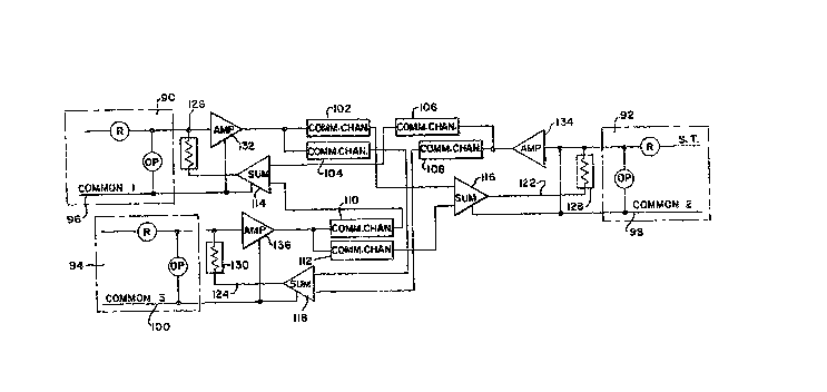
block diagram schematic of an active pilot wire apparatus
for coupling together three electromechanical units depict-
ed in Figure 4 exemplifies the aforementio~ed extendedaspect of applicants' invention.
Referring to Figure 4, each of the three electro-
mechanical units depicted by the blocks 90, 92 and 94 may
be coupled to'its respective set of power lines through a
corresponding set of current transformers (not shown) much
the same as de~cribed in connection with the embodiment of
Figure 1. Similarly, each of the electromechanical units
90, 92 and 94 includes its own restraint relay coil appara-
tus R and operating relay coil apparatus OP. And in
addition, each of the electromechanical units 90, 92 and 94
includes its own separate and independent current return
path 96, 98 and 100, respectively.
In accordance with this extended aspect of the
p~esent invention, the active pilot wire apparatus includes
a multiplicity of active communication channels for cou-
pling each electromechanical unit to all of the other
electromechanical units of the plurality. For example, the
'' ~ I C~ ~
11 52,95~
electromechanical unit 90 is coupled to the electro-
mechanical unit 92 through the communication channel 102
and coupled to the elec~romechanical unit 94 through the
communication channel 104. Similarly, the electro-
mechanical unit 92 is coupled to the~ electromechanicalunits 90 and 94 through the communication channels 106 and
108 respectively; and electromechanical unit 94 is coupled
to the electromechanical units 90 and 92 through the
communication channels 110 and 112, respectively. The
lQ communication channels 102 through 112 comprise similar
encoder/decoder and communication medium elements similar
to those described in connection with the embodiment of
Figure 3.
In addition, the active pilot wire apparatus
in~ludes a plurality of buffer amplifiers 114, 116 and 118
corresponding to each o the electromechanical units 90, 92
and 94. Each of the buffer amplifiers 114, 116 and 118 is
coupled to its respective communication channel3 and more
particularly, the decoder elements thereof, for summing the
reconverted analog signals generated by such respective
decoder units. For example, the buffer unit 114 sums the
analog signals of the communication channels 106 and 110,
the buffer amplifier 116 sums the anaIog signals of the
communication channels 102 and 112 and the buffer amplifier
118 sums the analog signals of the communication channels
104 and 108. Moreover, each buffer amplifier 114, 116 and
118 generates an analog signal 120, 122 and 124 which in
each ca~e is representative of the summation of its respec-
tive reconverted analog signals.
Still further, a plurality of impedance elements
126, 128 and 130 corresponding to each electromechanical
unit 90, 92 and 94, respectively, may be disposed between
its respective analog summation signal and corresponding
operating relay coil voltage signal. The current diverted
through the impedance elements 126, 128 and 13Q is a
function of the coupled signals at either end thereof.
Additional amplifiers 132, 134 and 136 corresponding to the
~79~i6
12 52,555
electromechanical units 90, 92 and 94, respectively, may be
included in the active pilot wire apparatus to increase the
power capabilities of driving a plurality of communication
channels as governed by the operating relay coil voltage
signal in each case.
The operation of ~he extended embodiment is
similar in nature to that described in connection with the
embodiment of Figure 3 with the exception of the summation
of voltage signals in the buffer amplifiers 114, 116 and
118. That is, the diversion of energiæing current through
the impedance elements 126, 128 and 130 from the corres-
ponding operating relay coil apparatus OP is now dependent
on the voltage signals from more than one other electro-
mechanical unit.
Another feature of the common active communica-
tion channel approach is the inclusion o dirsct transfer
trip apparatus to share the common channel utilized for
signal transfer between the electromechanical units of the
current differential protective reLay. The direct transfer
trip function induces signal~ to be transmitted either
upstream or downstream from a faulted power line section
where a breaker has failed to open. These direct transfer
trip signals are supplied directly to an upstream or
downstream breaker unit to operate the breaker to interrupt
current through the faulted section independent of the
energization of its corresponding operating relay coil.
The instant feature permits sharing of the active pilot
wire communication channel for performing the direct
transfer trip function and permits disabling of the operat-
ing relay coil apparatus from effecting a power lineinterruption inadvertently. That is, an inadvertent
current interruption o~ the power line section by a corre-
sponding operating relay coil apparatus is precluded during
the transmission of the direct transfer trip signal over
the common active communication channel.
A suitable design for embodying the direct
transfer trip (DTT) apparatus is shown in the block diagram
'79~
, .~
13 52,~o
schematic of Figure 5. The communication channel may
comprise the elements of an encoder 74, commUnlca~ion
medium 82 and decoder 78 which are similar to the same
numbered elements described in connection with the embodi-
S ment of Figure 3. Accordingly, the communication channelcouples the electromechanical units 32 and 34 by providing
signal communication therebetween. In accordance with this
inventive feature, a DTT initiate circuit 140 is governed
by a DTT keying signal 142 to initiate a DTT signal 144 for
shared transmission with the electromechanical unit signal
VA over the common active communication channel between the
two electromechanical units 32 and 34. In addition, a DTT
receive circuit 146 is operative to receive the DTT signal
148 from the communications channel and generate a trip
lS signal 150 in response thereto. In the instant embodiment,
a switch 152 and 154 is coupled in parallel with the
operating relay coil apparatus OP of its corresponding
electromechanical unit 32 and 34, respectively. Each
switch 152 and 154 which may be either an electronic or
electromechanical type, for example, is governed to the
closed position by the corresponding DTT signal 144 and
150, respectively, to permit total current diversion from
the operating relay coil apparatus of its respective
electromechanical unit, thereby precluding the operation
thereof during the generation of the DTT signal.
An alternate design for embodying the direct
transfer trip apparatus is shown in the` block diagram
schematic of Fiyure 6. The instant embodiment takes
advantage of the active pilot wire apparatus embodiment
described in connection with Figure 3. In the instant
embodiment, switches 160 and 162 are coupled respectively
between the decoder buffer amplifier combinations of 78/50
and 80/54. The switches 160 and 162 which may be either
electronic devices or electromechanical devices, for
example, are operative to pass or interrupt the analog
signals reconverted by their respective decoder units.
~7~
14 52,965
The embodiment of Figure 6 includes the
additional apparatus o a DTT initiate circuit 164 for
conducting the DTT keying signal 166 through another
communication channel comprising the encoder unit 76,
communication medium 82 and decoder unit 80 to a DTT
receive circuit 168. In response, the DTT receive circuit
168 generates a trip signal 170 which is transmitted in the
opposite direction of that of the trip signal 150.
The switches 160 and 162 are operated to the open
position by the signals 150 and 170, respectively. When
either switch 160 or 162 is operated to its open position,
the voltage signal at the input of its respective ampiifier
50 or 54 is altered to cause an increase in current through
the respective impedance element 58 or 60. In this manner,
the energization current of the operating relay coil is
diverted through the parallel path of its corresponding
impedance element which prevents energization o the
operating relay coil apparatus in either case. In essence
then, a DTT signal is permitted to share the communication
channel of the active pilot wire pair apparatus and while
doing so, the operating relay coil is precluded from being
: operated inadvertently to activate its corresponding
brea~er unit.
While various features of the present invention
have been described hereinabove using various embodiments,
it is understood that the present invention should not be
limited in any way to such embodiments; but rather con-
strued in breadth and broad scope according to the appended
claim language.