Note : Les descriptions sont présentées dans la langue officielle dans laquelle elles ont été soumises.
` ~68170
The present invention relates to vessels,
especially cargo vessels, in general and more particularly
to improvements in method and systems for shielding
cargoes from condensate in the holds of seagoing vessels
and similar conveyances.
Cargoes which are likely to spoil and/or to
be otherwise affected by condensate in the cargo area
of a seagoing vessel or the like are normally confined
in sealed bags or other types of receptacles so as to
prevent direct contact between the stowed material and
condensate which is contained in the cargo area and is
likely to deposit on the surrounding walls in response
to changes of temperature. The simplest way of stowing
many types of cargoes would be to pour or otherwise
introduce the goods into the cargo area in unconfined
state, i.e., into direct contact with the walls
surrounding the space which is allotted for the storage
of cargo. However, moisture in the air which fills
the remainder of the storage area is likely to deposit
on the surrounding walls and to trickle down into
contact with the stored goods. This leads to spoilage
and/or other problems. When the vessel travels from
a warmer climate to a colder climate, the temperature
in the cargo area is likely to sink so that the moisture
in the air filling the space above and/or around the
cargo condenses and deposits on the walls with the
aforediscussed drawbacks as concerns the appearance
and/or quality of the stored goods. The dew point can
be reached rather rapidly if the difference between the
temperature at the port of lading and the temperature
7~)
-- 3 --
in the the selected sea lane is very pronouneed.
It is well known that the temperature of
walls surrounding the eargo area is likely to sink
much more rapidly than the temperature of stowed
cargo. The condensate which deposits on the surfaces
of such walls gathers into droplets which trickle
downwardly and contact the cargo or other receptacles
for stored cargo. One presently known proposal to avoid
condensation of moisture whieh is eontained in the air
in the eargo area includes ventilation of cargo area.
This is effeetive only if the eargo is subdivided into
batehes whieh allow for the passage of eireulating air
therebetween and therearound. However, it is often
desirable to store bulk eargo in the hold of a vessel
without any partitioning, i.e., in the form of a
eoherent mass whieh fills the eargo area to a certain
extent, the remainder of the area being filled with air
whieh enters such area during admission of bulk cargo.
Therefore, simple pouring of bulk cargo into the hold
of a vessel is possible only if the eargo is not
likely to spoil or to be otherwise adversely affeeted
by eondensed moisture. Consequently the transport of a
wide variety of goods is possible only by ineurring
the expense of introdueing sueh goods into bags, saeks,
eontainers or other types of reeeptaeles whieh ean
effeetively prevent direet eontaet between the goods
and the eondensate. A typieal example of sueh goods
is eoffee whieh could be transported in bulk form at
a fraction of the present eost but for the fact that it
can be affected by condensate and, therefore, must be
i268171~
-- 4 --
confined in relatively small receptacles in the form
of bags. In addition, the bags must be stowed in the
hold of a ship in such a way that there is enough room
for circulation of air in order to reduce the likelihood
of condensation of moisture along the walls and/or on
the bags. All this contributes significantly to the
cost of transport of goods which could be shipped at
a fraction of the present cost if they could be simply
poured into the cargo area without prior confinement
in bags or similar relatively small receptacles.
Storage in bags or the like also contributes to higher
cost of evacuation of the contents of ships at the port
of destination.
One feature of the invention resides in the
provision of a method of conditioning the cargo area of
a vessel wherein the cargo (especially bulk cargo) is
surrounded by walls which are in direct contact therewith
as well as with moisture-containing air which is
confined in the cargo area. The method comprises the
steps of maintaining the temperatures of confined air
as well as of the walls at values such as to prevent
condensatlon of moisture on the walls and resulting
contact between such condensed moisture and the cargo.
The method can further comprise the step of regulating
the moisture content of air in the cargo area so as to
further reduce the likelihood of condensation of moisture
on the walls.
The maintaining step can include maintaining
the temperature of the walls, as well as the temperature
of confined air, at an at least substantially constant
i26817CI
-- 5
value. Also, the maintaining step can include monitoring
the temperatureand the moisture content of air in the
cargo area, utilizing the monitored values to ascertain
the dew point of moisture in the air in the cargo area,
and maintaining the temperature of air and the walls
above such-dew point.
The method can further comprise the step of
reducing the moisture content of air in the cargo area.
The maintaining step can include heating the
air in the cargo area by causing such air to exchange
heat with the walls. The temperature of air in the
cargo area can be monitored in one or more selected
(strategic) zones of the cargo area and/or in the region
or regions of one or more selected portions of the walls.
The maintaining step can comprise heating the
air in the cargo area and/or the walls with heat which
is generated by the engine or engines of the vessel.
Such heating step can include establishing an exchange
of heat between the engine or engines and a heat
exchange medium, and establishing a transfer of
heat between air in the cargo area and/or the walls on
the one hand and the heat exchange medium on the other
hand. For example, the heat transferring step can
include transferring heat from a liquid heat exchange
medium to those sides of the walls which face away from
the cargo area.
If the maintaining step includes contacting
the walls with a heat exchange medium, such maintaining
step can further comprise maintaining the temperature
of the heat exchange medium at an at least substantially
i268170
-- 6 --
constant value. Still further, the maintaining step
then includes (or can include) clrculating the heat
exchange medium while in contact with the walls.
As a rule, the walls will be contacted by a
heat exchange medium whose temperature is above the
dew point of moisture in the air which is confined in
the cargo area. Such method then preferably further
comprises the steps of monitoring the temperatures of
air and of the walls, and circulating the heat exchange
medium at a rate which is a function of the monitored
temperatures so as to thereby regulate the rate of
delivery of heat to the walls and/or to the mass of
confined air.
The maintaining step can further comprise
directing a gaseous heat exchange medium against those
sides of the walls which are contacted by cargo and
air in the cargo area and effecting an exchange of heat
between the gaseous heat exchange medium and the walls.
Such method can further comprise the step of circulating
the heat exchange medium along and around the cargo
in the cargo area. Still further, such method can
comprise the additional step of maintaining the
temperature of the heat exchange medium above the
dew point of moisture in the air which is confined in
the cargo area. Still further, such method can comprise
the step of regulating the moisture content of the
heat exchange medium.
Another feature of the invention resides in
the provision of a vessel, such as a cargo ship, which
comprises wall means defining at least one cargo-containing
~268~
-- 7
area which is arranged to be filled with cargo and
moisture-containlng air and wherein the cargo contacts
the wall means, and regula~ing means for maintaining
the temperature of the wall means and of the mass of
air which is confined in the cargo area at values such
as to prevent condensation of moisture on the wall
means. Such vessel can further comprise means for
varying (e.g., reducing) the moisture content of
air in the cargo area. Still further, the vessel can
be equipped with means for monitoring the temperature
of the wall means (such monitoring means can include
sensor means in direct contact with the wall means),
means for monitoring the temperature of air in the cargo
area, and/or means for monitoring the moisture content
of air in the cargo area. The means for monitoring
the moisture content of air can be provided on the
wall means.
The regulating means can comprise a source of
heat exchange medium and means for effecting a
transfer of heat between the heat exchange medium and
air in the cargo area. For example, air in the cargo
area can be heated through the medium of the wall means
which, in turn, is heated by the heat exchange medium.
The wall means comprises top, bottom and side
walls and the wall heating means can include means for
heating at least one of these walls. The top wall can
include or constitute a hatch cover and the regulating
means can comprise means for circulating a heat exchange
medium through the hatch cover. At least one wall of
the wall means is preferably hollow and defines an
~268170
-- 8
internal compartment, and the regulating means can
comprise means for circulating a heat exchange medium
through such compartment or compartments. For example,
the top wall can be provided with one or more compartments
for circulation of a heat exchange medium therethrough.
Analogously, the bottom wall can be hollow and the
regulating means can include means for circulating a
suitable heat exchange medium through the compartment
or compartments of the bottom wall. Means (e.g., ribs,
fins or the like) can be provided in the interior of
wall means to promote the transfer of heat between the
heat exchange medium in the compartment or compartments
and the wall means.
It is also possible to install at least one
heating coil in the wall means and to convey a
suitable gaseous or liquid heat exchange medium through
the coil. The wall means can include inner wall means
contacting the cargo in the cargo area and outer wall
means defining at least one compartment with the
inner wall means; the heating coil is then preferably
mounted in the compartment or compartments and on the
inner wall means. Heat insulating means can be disposed
in the compartment or compartments along the outer
wall means.
The engine or engines of the vessel can heat
one or more supplies of a suitable heat exchange medium
(e.g., water or another coolant for the engine), and
the regulating means can comprise suitable means for
effecting a transfer of heat between such heat exchange
medium and the wall means and/or air which is confined
Z68170
in the cargo area. The coolant itself can constitute
the heat exchange medium which directly contacts the
wall means; alternatively, the heated coolant can transfer
heat to a second heat exchange medium which communicates
the thus transmitted heat to the wall means. The heat
exchange medium can be a gaseous or hydraulic fluid, e.g.,
air or water. If the heat exchange medium is a gas, the
regulating means can comprise one or more nozzles
installed in the wall means and serving to discharge
the gaseous heat exchange medium into the cargo area.
Such nozzle or nozzles can be mounted in or on the
bottom wall and/or in or on the to2 wall of the wall
means.
One or more fans can be provided to circulate
the mass of air in the cargo area.
It is also possible to employ regulating means
in the form of or including one or more electric heaters.
If the wall means defines several compartments,
it is preferably formed with one or more passages
connecting the neighboring compartments to each other
so as to allow for circulation of a heat exchange
medium in as well as between the compartments.
For example, if the top and side walls of
the wall means are provided with discrete compartments,
the compartment in the top wall can be connected with
the compartment of each side wall by at least one passage
allowing for circulation of heat exchange medium between
the compartment of the top wall and the compartment or
compartments of the side walls. The top wall is
preferably separable from the adjacent side walls in
~268~70
-- 10 --
the regions of the passages, and the vessel is preferably
equipped with means for separably and sealingly securing
such walls to each other.
The novel features which are considered as
characteristic of the invention are set forth in
particular in the appended claims. The improved
system itself, however, both as to its construction
and its mode of operation, together with additional
features and advantages thereof, will be best understood
upon perusal of the following detailed description of
certain specific embodiments with reference to the
accompanying drawing.
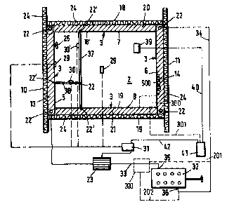
FIG. 1 is a somewhat schematic transverse vertical
sectional view of the hull of a cargo vessel which
embodies the improved conditioning system; and
FIG. 2 is a horizontal sectional view as
seen in the direction of arrows from the line II-II
of FIG. 1.
The drawing shows a vessel having a hull 1
which includes a wall structure 3 defining at least one
cargo area or hold 2. The wall structure 3 completely
surrounds the cargo area 2 and includes a bottom wall 4,
two side walls 5, 6 a top wall 9, and two transverse
walls 7 and 8. The side walls 5 and 6 extend in the
longitudinal direction of the vessel. The illustrated
top wall 9 constitutes or includes a hatch cover.
The wall structure 3 includes a set of inner
walls which are shown by heavy lines and a set of outer
walls which define with the adjacent inner walls discrete
compartments indicated by hatching. FIG. 1 shows the
~68~qo
outer walls 10, 11, 12, 16 which respectively form part
of the side walls 5, 6, bottom wall 4 and top wall 9.
The outer walls 18, 19 of thetransverse walls 7, 8 are
shown in FIG. 4. The compartments 13 and 14 are
inwardly adjacent to the outer walls 10, 11, the compartment
15 is inwardly adjacent to the outer wall 12, the compart-
ment 17 is inwardly adjacent to the outer wall 16, and
the compartments 20, 21 are inwardly adjacent to the
respective outer walls 18, 19. The inner walls are
denoted by the same reference characters as the
corresponding outer walls but each thereof is followed
by a prime.
The drawing shows that each compartment
extends along the full length and width of the corres-
ponding inner and outer walls. The inner sides of such
compartments are separated from the cargo area 2 by
the outer sides 28 of the corresponding inner walls.
The wall structure 3 further defines passages 22 which
connect the neighboring compartments with each other.
For example, and as shown in the upper portion of FIG. 1,
the compartment 17 of the hollow top wall 9 communicates
with each of the compartments 13, 14 in the hollow
side walls 5 and 6 by at least one passage 22. This
allows for circulation of a suitable heat exchange
medium (which can be a gas or a liquid) not only in
each of the compartments but also between neighboring
compartments. One of the presently preferred heat
exchange media is hot water. Such medium can constitute
a coolant for the engine or engines 32 of the vessel
which embodies the present invention. In other words,
1268170
- 12 -
the heat exchange medium can perform a plurality of
functions including cooling the engine or engines 32
as well as of preventing condensation of moisture in the
mass of air which is entrapped in the cargo area 2 at
a level above the confined cargo and is in direct
contact with the adjacent inner walls of the structure
3. FIG. 2 shows a supply conduit 33 receiving heated
coolant from the outlet 35 of the cooling unit for the
engine or engines 32 and such conduit means contains a
suitable pump 23 which forces a stream of heated coolant
into the compartments of the wall structure 3. FIG.
2 merely shows a single conduit 33 and a single pump
23 for delivery of heated coolant (li~uid heat exchange
medium) into the connecting passage 22 between the
compartments 13 and 21. ~owever, it is to be understood
that the vessel can be provided with seueral supply
conduits which can admit discrete streams of heated
coolant to several compartments of the wall structure
3. FIG. 2 further shows a single return conduit 34
which receives spent heat exchange medium from the
passage 22 between the compartments 14 and 20 to return
such heat exchange medium (coolant whose temperature
has been reduced as a result of heat transfer to the
wall structure 3) into the inlet 36 of the cooling system
for the engine or engines 32. The pump or pumps 23
ensure that the heat exchange medium is circulated not
only in but also between the compartments of the wall
structure 3 to thus effect a more satisfactory transfer
of heat from such heat exchange medium to the inner
and outer walls of the structure 3. Such circulation
-
12fi8170
- 13 -
of the heat exchange medium further ensures that the
conditioning of the inner and outer walls of the wall
structure 3 is more uniform. The operation of the
illustrated pump 23 is regulated by a control unit 31
which has an output connected with the motor for the pump
23 as well as an input for signals from a temperature
monitoring device 29 in the form of a sensor attached
to the inner side of the inner wall 10'. A second input
of the control circuit 31 is connected with the corres-
ponding output of a computer 41 by a conductor 42.The computer 41 receives signals by way of a
conductor 40 which is connected to a temperature monitoring
device or sensor 39 installed in the cargo area 2 and
serving to ascertain the temperature of the confined
mass of air. A further sensor 29' can be installed in
the cargo area 2 to transmit signals to the corresponding
input of the control unit 31. Additional temperature
monitoring devices 30 and 30' in the form of sensors
can be installed within the confines of the wall structure
3, for example, on a transversely extending partition
38 and a longitudinally extending partition 37. Such
partitions can be provided to subdivide the cargo area
2 into several smaller chambers, depending upon the
quantity of bulk cargo which is to be transported in
a particular chamber. The partitions 37 and 38 are
preferably removable and/or shiftable so as to allow
for the establishment of larger or smaller chambers.
The operation of the control unit 31 is preferably
such that the temperature of air in the cargo axea 2 is
at least substantially constant. The motor of the pump 23
12681~
- 14 -
is turned on or off as required to ensure that the
temperature of air in the area 2 will remain constant
during the entire voyage of the vessel.
It is assumed that a substantial part of the
cargo area 2 is filled with bulk cargo which directly
contacts the adjacent inner walls of the structure 3. It
is also assumed tha~ such cargo is sensitive to condensate,
i.e., that condensate could affect the appearance and/or
other characteristics of cargo in an undesirable way so
that the moisture which is contained in the mass of air
above the bulk cargo in the area 2 should be prevented
from condensing at the inner sides of the inner walls
of the structure 3. Some moisture containing air
invariably penetrates into the cargo area 2 during loading
of cargo through the top portion of the wall structure
3. It will be readily appreciated that the ~oisture
content of confined air can fluctuate within a very
wide range. This depends on the climate in the port
of lading, on the time of the year when the area 2 is
being filled with cargo and on other factors. The
temperature of cargo also depends on the temperature of
the surrounding atmosphere in the port where the vessel
is anchored to take on cargo. The hatch cover of the
top wall 9, or the entire top wall 9 is placed on top
of the side walls 5, 6 and transverse walls 7, 8 when
the area 2 is filled with cargo to the desired or
required eY.tent. This seals or substantially seals
the cargo area 2 from the surrounding atmosphere.
If the loaded vessel takes a northerly route, it is
highly likely that the temperature of water as well
~68170
- 15 -
as the temperature of the surrounding air will be
progressively lower, i.e., below the temperature at
the port of lading. The differences between such
temperatures can be very substantial, for example,
when the vessel leaves a tropical port and takes a
course toward a port in a northern state or country.
The ou~er walls of the structure 3 are
subjected to the most pronounced cooling action.
The wall structure 3 then tends to cool the air
which is entrapped in the cargo area 2. In the absence
of any measures to the contrary, this would lead to
a reduction of the temperature of the mass of air in
the cargo area to below the dew point of the moisture
therein so that the moisture would condense on the inner
sides of the inner walls of the wall structure 3. Such
condensation is prevented by heating the wall structure
3 as well as the mass of air in the cargo area 2,
preferably through the medium of the inner walls of the
structure 3. As mentioned above, such heating is or can
be effected by the circulating heat exchange medium
which is supplied by the pump 23 and constitutes the
supply of heated coolant which issues from the cooling
system for the engine or engines 32 at the outlet 35 and
is returned to such cooling system at the inlet 36.
Condensation of moisture which is contained in the mass
of air in the cargo area 2 can be prevented all the way
along the non-covered portions of the inner sides of
the inner walls of the structure 3 because the
compartments between the inner and outer walls preferably
extend all the way along the major portions or the entire
~268~0
- 16 -
inner and outer wali~;$~ias tQ enable the heat exchange
medium to maintain the temperature of the inner walls,
and hence the temperature of confined air, at values
which invariably prevents condensation of moisture. The
control unit 31 ensures that the pump 23 is operated
for periods of time and at frequencies such that the
circulating heat exchange medium reliably prevents
condensation of moisture along the inner sides of the
inner walls above the level of the stowed cargo in
the area 2. The purpose of the temperature monitoring
sensors 29, 29', 30, 30' and 39 is to generate signals
at strategic points in the interior of the wall structure
3 and along the inner sides of the inner walls so as to
ensure that the control unit 31 can properly select
the duration and frequency of operation of the motor
for the pump 23.
The reference character 200 denotes in FIG. 2
a schematically shown heat exchanger 200 which can be
installed in the conduit 33 so as to receive heated
coolant from the outlet 35 of the cooling system for
the engine or engines 32. This heat exchanger then
contains its own supply of a different heat exchange
medium (for example, a gas) which is circulated by the
pump 23 and/or by one or more additional pumps so as to
flow through and between the compartments which are
defined by the top, bottom, side, front and rear walls
of the structure 3. In such modified construction,
spent heat exchange medium is returned into the heat
exchanger 200 by a line 201. The conduit 34 between
one or more connecting passages 22 and the inlet 36
12~8i7C~
- 17 -
of the cooling system for the engine or engines 32 is
then omitted or sealed. A return conduit 202 is then
provided to return s~ent coolant from the heat exchanger
200 to the inlet 36 of the cooling system for the engine
or engines 32. As a rule, coolant which issues from
the outlet 35 of the cooling system for the engine or
engines 32 is sufficiently hot to be in a condition
to exchange heat with air or another gas which is
thereupon circulated through the compartments of the wall
structure 3. As mentioned above, the heat exchange
medium which is supplied by the pump or pumps 23
directly heats the wall structure 3 whereby the wall
structure transmits heat to the mass of air which is
confined in the cargo area 2. This prevents deposition
of condensate along the inner sides of the inner walls
of the structure 3.
The inner walls of the structure 3 can directly
heat the cargo and the mass of air in the area 2.
However, it is equally within the purview of the
invention to set up one or more heating elements or
aggregates in the cargo area 2 itself so that such
aggregate or aggregates directly heat the confined mass
of air as well as (if necessary) the confined bulk cargo.
The aforediscussed partitions 37 and 38 can be said
to constitute such heating elements because they receive
heat from the inner walls of the structure 3 and
transmit heat directly to air and cargo in the
area 2.
The partitions 38 and 37 which are shown in
FIG. 2 are hollow, and the improved conditioning system
1268~70
- 18 -
is provided with additional passages 22' which allow
the heat exchange medium to flow between the compartments
of the wall structure and the compartments of the hollow
partitions 37 and 38. This converts the partitions 37
and 38 into discrete heating elements which are installed
in the interior of the space 2 to transmit heat directly
to the mass of moisture-containing air abovè the bulk
cargo as well as to the bulk cargo itself.
~s mentioned above, the output of the temperature
monitoring sensor 39 in the cargo area 2 is connected
with an inlet of the computer 41 by a conductor 40.
This enables the computer 41 to evaluate the temperature
and/or moisture content of air in the area 2 and to
transmit appropriate signals to the control circuit 31
via conductor 42. The sensor 39 can comprise means for
monitoring the temperature as well as the moisture
content of air in the cargo area 2. The conductor 42
can constitute a two-way conductor which transmits
signals from the computer 41 to the control unit 31 as
well as in the opposite direction. In this manner, the
computer 41 can receive signals which are generated
by the sensors 29, 29', 30 and 30'. Transmission of
such signals to the computer 41 enables the latter to
continuously ascertain the dew point of moisture in the
mass of air which is confined in the cargo area 2 and
to transmit appropriate signals to the control unit
31 for the motor of the pump 23. Moreover, the computer
41 can transmitsignals to a suitable moisture withdrawing
or admitting device which ensures that the moisture
content of air in the cargo area 2 is maintained within
12681q~
- 19 -
an optimum range. The programming of the computer 41 is
preferably such that the circulation of heat exchange
medium through the compartments of the wall structure 3
and partitions 37, 38 suffices to maintain the temperature
of the inner walls of the structure 3 and of the mass of
air above the bulk cargo in the area 2 slightly above
the dew point of moisture in such air. In other words,
the selected mode of regulation can be such that the
conditioning system which is shown in the drawing barely
prevents condensation of moisture along the inner sides
of the inner walls of the structure 3 and/or along the
exposed surfaces of the partitions 37 and 38. Such
mode of operation renders it possible to lower the
temperature of air in the cargo area 2 below the
temperature which prevailed in the area 2 during
introduction of bulk cargo at the port of lading.
Irrespective of the selected temperature of mass of air
in the area 2, the prevailing conditions should be such
that moisture which is contained in such air cannot
deposit on the cargo and/or on the inner walls of the
structure 3 and/or on the partitions 37, 38. In order
to ensure more reliable monitoring of temperature and
moisture content of air in the cargo area 2, the latter
can contain two or more sensors 39 which are strategically
distributed within the confines of the wall structure 3
so as to reliably inform the computer 41 of the conditions
prev~iling in the cargo area 2. This enables the
computer to properly control the unit 31 and the motor
for the pump 23.
It is also possible to reduce the moisture
126817~
- 20 -
content of air in the cargo area 2. The advantages o F
such mode of operation will be readily appreciated.
Thus, if the air contains a lower percentage of moisture,
the latter is much less likely to condense on the inner
walls of the structure 3 and/or on the cargo in the
area 2 and/or on the partitions 37, 38. The character
300 denotes a dehumidifier which is installed in the
cargo area 2 and is operable in response to signals
from the computer 41 via conductor means 301 so as to
extract moisture if the moisture content of air in the
area 2 is excessive. The dehumidifier 300 can be
designed to return dehumidified air into the space
within the confines of the inner walls of the structure
3.
When heating the mass of air in the cargo area
2, one should ensure that the temperature in each and
every region of the area 2 will remain above the dew
point of moisture in the confined mass of air. In
other words, the exchange of heat between the inner
walls of the structure 3 and the mass of air which is
confined in the cargo area 2 should be such that the
temperature of air is above the dew point not only in
the regions which are immediately ad~acent to such
inner walls but also in that portion or those portions
of the cargo area 2 which are remotest from the inner
walls of the structure 3. The likelihood of unequal
heating of air in the cargo area 2 by the inner walls
of the structure 3 is rather pronounced because bulk
cargo is normally a poor conductor of heat. Furthermore,
the entrapped mass of air also constitutes a poor
i268~70
- 21 -
conductor of heat. Therefore, the temperature of
inner walls of the structure 3 must be increased in
such a way as to take into full consideration the
thermal conductivity of bulk cargo and air in the cargo
area 2. This is the function of the computer 41 and
of sensors which are installed in the cargo area 2. It
has been found that the installation of hollow
partitions (such as the illustrated partitions 37, 38
in FIG. 2) contributes significantly to uniform
distribution of heat in the mass of air which is confined
in the area 2 above the mass of bulk cargo. If
desired, the area 2 can contain more than two partitions
which are distributed in such a way as to ensure more
uniform heating of the entire mass of air above the
body of bulk cargo.
If the system of FIGS. l and 2 employs a
gaseous heat exchange medium which is circulated by one
or more pumps 23 or analogous fluid flow machines through
the compartments of the wall structure 3, the gaseous
heat exchange medium can also be admitted directly
into the cargo area 2 so as to directly exchange heat
with the confined mass of air. An advantage of such
mode of operation is that the dehumidifier 300 can be
omitted because the gaseous heat exchange medium can
alter the moisture content of air in the area 2 above
the bulk cargo. If such admission of gaseous heat
exchange medium into the area 2 is to take place, the
gaseous heat exchange medium can be admitted through one
or more nozzles 400 which are provided in the inner
wall 16' of the top wall or hatch cover 9 and/or through
-`` i26B170
one or more nozzles 400 which are provided in the
inner wall 12' of the bottom wall 4 of the structure 3.
Direct heating of air in the cargo area 2 by a gaseous
heat exchange medium brings about the aforementioned
advantage that the moisture content of entrapped air
can be regulated without resorting to a discrete
dehumidifier. However, a relatively dry or very dry
gaseous carrier medium cannot be readily heated to an
elevated temperature so that the heating of such heat
exchange medium entails the consumption of substantial
amounts of energy which may not be warranted under any
and all circumstances. A satisfactory solution is that
of using a first heat exchange medium to flow in and
through the compartments of the wall structure 3 in
order to heat the inner walls of such structure and to
thereby indirectly heat the confined mass of air, as
well as of using one or more nozzles 400 in order to
discharge a hot gaseous carrier medium directly into the
cargo area 2. Alternatively, one and the same gaseous
carrier medium can be utilized for circulation in the
compartments of the wall structure 3 as well as for
admission into the cargo area 2 for directly contacting
and influencing the temperature and moisture content
of the confined mass of air. If the system employs
one or more nozzles 400 for admission of a dry gaseous
carrier medium into the cargo area 2, it is desirable
or advisable to install in the area 2 one or more air-
circulating means such as a fan 25 which is schematically
shown in the upper left-hand portions of FIGS. 1 and 2.
In order to avoid excessive losses of heat
1268~
- 23 -
energy as a result of circulation of a liquid and/or
gaseous heat exchange medium in the compartments of
the wall structure 3, the system preferably further
comprises layers 24 of suitable insulating means installed
in the compartments of the wall structure 3 and preferably
adjacent to the inner sides of the outer walls. Such
insulating layer or layers 24 are preferably provided
all the way around each and every compartment in the
wall structure 3. It has been found that the provision
of thermal insulating means greatly reduces the heat
energy requirements of the conditioning system. Each
of the illustrated insulating layers 24 preferably
extends along the entire inner side of the respective
outer wall.
In order to enhance the transfer of heat
between the heat exchange medium which circulates in
the compartments of the wall structure 3 and the inner
walls of such structure, the outer sides 28 of the
inner walls are preferably provided with ribs, fins or
similar projections or protuberances 43 (see the left-
hand portion of FIG. 1) which are surrounded by the body
of circulating heat exchange medium and transfer heat
to the adjacent inner walls of the structure 3. It is
clear that similar heat transfer promoting devices can
also be provided in the cargo area 2. This is shown
schematically at 143 at the inner side of the inner
wall 16' of the top wall 9 shown in FIG. 1. The ribs
or fins 143 promote the exchange of heat between the
wall structure 3 and the mass of air which is confined
in the area 2 above the bulk cargo.
1268170
- 24 -
It is not always possible to avoid certain
slight differences between the temperature of an inner
wall and the temperature of the adjacent body of air
in the cargo area 2. The purpose of the fan or fans 25
is to ensure more uniform distribution of heat in the
entire mass of air above the bulk cargo in the area 2.
The fan or fans 25 are preferably installed on one or both
side walls and/or on the transverse wall or walls close
to the top wall 9 of the structure 3. Continuous circulation
or agitation of air in the cargo area 2 contributes to a
substantial reduction of the likelihood of condensation
of moisture along the inner sides of the inner walls of
the structure 3.
As mentioned above, the nozzle or nozzles 400
can be provided not only in the top wall 9 but also
in the inner wall 12' of the bottom wall 4. In other
words, such nozzle or nozzles can discharge a gaseous
heat exchange medium into bulk cargo which is confined
in thearea2. It will be readily appreciated that
the pressure of a gaseous carrier medium which is
admitted to the nozzle or nozzles 400 in the inner wall
12' of the bottom wall 4 must be raised sufficiently to
enable such carrier medium to penetrate through the
bulk cargo and to mix with the mass of moisture-
containing air above the upper surface of the cargo.
Referring again to FIG. 1, the lines 26
denote the surfaces where the top wall 9 abuts against
the adjacent side walls 5, 6. Such surfaces are
preferably provided in the regions of the respective
connecting passages 26. The reference characters 27
~268~70
- 25 -
denote locking devices for releasably securing the
top wall 9 to the neighboring walls of the structure 3.
The locking devices 27 are removed or loosened when the
top wall 9 is to be removed or partially lifted so as
to allow for introduction of cargo into or for evacuation
of cargo from the area 2. The connections between the
top wall 9 and the adjacent walls of the structure 3
are preferably airtight so as to prevent uncontrolled
escape of air from the area 2 and/or uncontrolled
admission of atmospheric air into such area. Moreover,
such airtight sealing is desirab~e in order to prevent
the escape of heat exchange medium from the compartment
17 in the interior of the top wall 9 and/or from the
compartments which are in communication with the
compartment 17. If the heat exchange medium is a liquid
(normally water), it is evacuated from the compartment
17 before the top wall 9 is lifted to permit admission
of cargo into or evacuation of cargo from the area 2.
It is further within the purview of the
invention to replace the heat exchange medium in the
compartments of the wall structure 3 with electric
heating coils one of which is shown at 500. Such
heating coils are preferably mounted at the outer
sides 28 of the inner walls of the structure 3 and
are connected with a suitable source of electrical
energy to heat the inner walls in a controlled manner
for the purpose of preventing condensation of moisture
along the inner surfaces of the inner walls. Of course,
the electric heating coil or coils 500 can be provided
in addition to the compartments 13 etc., and the supply
1268170
- 26 -
of heat exchange medium which is being circulated in
and between such compartments. Still further, such
electric heating coils can be replaced with heating
coils in the form of tubes serving to circulate in their
interior a heat exchange medium which thereby transfers
heat to the inner walls of the structure 3. Combinations
of the aforediscussed features are possible. All that
counts is to ensure that moisture cannot condense along
the inner walls of the structure 3. The provision of
electric heating coils is desirable and advantageous
when the temperature of coolant for the engine or engines
32 of the vessel does not suffice to ensure adequate
heating of the wall structure 3 and of the mass of air
in the cargo area 2. Furthermore, if the cooling system
or systems for the engine or engines 32 cannot supply
adequate amounts of heat energy, the vessel can be
e~uipped with one or more additional water heaters for
the heat exchange medium which is then supplied to the
pump or pumps 23 for admission into the compartments of
the wall structure 3. As mentioned above, if electrical
heating elements are used, they are preferably mounted
at the outer sides 28 of the inner walls of the
structure 3. If the electrical heating elements are
used exclusively (namely without resort to a gaseous
or liquid heat exchange medium), they are preferably
uniformly distributed along the entire outer sides
28 of the inner walls of the structure 3.
It is clear that the improved system is equally
suited for properly conditioning air in a cargo area
for goods which are confined in receptacles, such as
~2681~0
-- 27 --
bags, sacks, containers or the like. If the goods are
stored in individual containers, it is desirable to
provided a requisite number of fans 25 or a sufficiently
large fan to ensure proper circulation of air around
the containers in the area 2. It has been found that
conditioning with hot air is particularly desirable
and advantageous if the area 2 contains a number of
discrete containers for bulk cargo or other types of
cargo. In such instances, the gaseous heat exchange
medium is preferably also admitted into the cargo
area 2 by way of nozzles in the top wall 9, in the bottom
wall 4 and/or in other walls of the structure 3.
An important advantage of the improved method
and system is that the cost of transport of many types
of bulk cargo and other types of cargo is reduced to
a fraction of the present cost. This is due to the fact
that cargo which is sensitive to condensate can be
transported in direct contact with the walls surrounding
the cargo area because the moisture in the air filling
the remainder of such area cannot deposit on the walls
and, consequently, cannot flow into direct contact with
the confined cargo. It will be readily appreciated that
the absence of the need for bags, containers and other
types of receptacles greatly reduces the cost of
transporting cargo in seagoing vessels or analogous
conveyances.
Another important advantage of the improved
method and system is that the cost of properly
conditioning the cargo area is relatively low or that
such cost can be selected within a wide range without
-
1268~70
- 28 -
the danger of condensation along the inner surfaces of
the walls surrounding the cargo area. Thus, the
complexity of the improved system can be increased or
reduced practically at will, as long as the system is
capable of adequately heating the walls and the
confined mass of air to a temperature which prevents
condensation of moisture along the walls and direct
contact between condensed moisture and the confined
cargo. In accordance with a very simple and inexpensive
embodiment of the improved system, the sensor or
sensors within the confines of the wall structure 3 are
distributed and designed to transmit signals which enable
the pump or pumps 23 to circulate a heat exchange
medium at a rate and for intervals such as to barely
prevent condensation of moisture along the inner sides
of the inner walls of the structure 3. This.can be
readily achieved if the temperature of air is
maintained at a value which approximates or equals
the temperature of confined cargo. The provision of the
computer 41 or other suitable evaluating means, as well
as of the control unit 31, contributes little to the
overall cost of transport of bulk goods in seagoing
vessels. In each and every instance, it is normally
preferred to construct and assemble the improved
system in such a way that the temperature of the mass
of air above the cargo in the area 2 fluctuates relatively
little or not at all. In other words, it is desirable
to heat or cool the wall structure 3 in such a way
that the temperature of the mass of air above the
cargo in the area 2 will remain at least substantially
1268~70
-- 29 --
constant .