Sélection de la langue

Search

Sommaire du brevet 1268943 

Énoncé de désistement de responsabilité concernant l'information provenant de tiers

Une partie des informations de ce site Web a été fournie par des sources externes. Le gouvernement du Canada n'assume aucune responsabilité concernant la précision, l'actualité ou la fiabilité des informations fournies par les sources externes. Les utilisateurs qui désirent employer cette information devraient consulter directement la source des informations. Le contenu fourni par les sources externes n'est pas assujetti aux exigences sur les langues officielles, la protection des renseignements personnels et l'accessibilité.

Disponibilité de l'Abrégé et des Revendications

L'apparition de différences dans le texte et l'image des Revendications et de l'Abrégé dépend du moment auquel le document est publié. Les textes des Revendications et de l'Abrégé sont affichés :

  • lorsque la demande peut être examinée par le public;
  • lorsque le brevet est émis (délivrance).
(12) Brevet: (11) CA 1268943
(21) Numéro de la demande: 1268943
(54) Titre français: PIEGE MECANIQUE
(54) Titre anglais: POWER SNARE
Statut: Durée expirée - après l'octroi
Données bibliographiques
Abrégés

Abrégé anglais


- 12 -
POWER SNARE
ABSTRACT OF THE DISCLOSURE
Animal traps are usually difficult to sterilize
in order to remove human odour therefrom and difficult to
hide when setting and often contain moving parts, tubes,
pins and the like. The present device consists of a pair
of spring arms made of heavy wire with a hairpin spring
at the junction thereof. Eye loops are formed one on
each distal end of the arms and one of these has a
slotted semi-circular plate welded otherwise secured into
the base of the eye. A freely running snare loop is
provided on one end of a standing part, in which part
extends through the slot in the disk or plate and through
a cotter pin assembly spanning the other eye and termi-
nates with a ferrule outboard of the other eye. A
trigger block is secured to the standing part inboard of
the slotted disk when the trap is set with the two arms
close together and being urged apart by the spring. The
snare loop is adjustable to catch the shoulders of the
animal, and the movement thereof disengages the trigger
block from the slotted disk and allows the arms to spring
apart tightening the snare loop and striking the animal a
heavy blow with the eye of the one arm.

Revendications

Note : Les revendications sont présentées dans la langue officielle dans laquelle elles ont été soumises.


CLAIMS
1. An animal trap comprising in combination a pair
of arms, a heavy duty hairpin spring joining said arms by one
end thereof and normally urging the distal ends of said arms
apart, and an eye loop formed on the distal end of each of
said arms, a free running snare loop formed in one end of a
standing part of a snare wire, the distal end portion of said
standing part extending through one of said eye loops and
means to detachably retain said distal end in the other of
said eye loops trigger means in said one eye loop cooperating
with said standing part to detachably hold said eye loops
juxtaposed with one another in a "set" position whereby said
eye loops are urged apart from one another by said spring
means when said trigger means is released, said trigger means
comprising a trigger plate secured across part of said one
eye and having a free edge, a slot formed In said free edge
and trigger block secured to said standing part of said
snare wire and spanning said slot when: said trap is in the
"set" position, with said standing end passing through said
slot.
2. The trap according to claim 1 in which the
portion of said trigger plate defining the sides of said slot
are inclined towards the outer side of said one eye thus
giving a slightly positive "set" to said block when engaged
therewith.
3. The trap according to claim 1 in which said
- 8 -

means to detachably retain said distal ends in the other of
said eye loops includes a cotter pin assembly spanning said
other eye loop an being secured thereto, said distal end of
said standing part engaging through said cotter pin of said
assembly and stop means on said distal end outboard of said
cotter pin.
4. The trap according to claim 2 in which said
means to detachably retain said distal ends in the other of
said eye loops includes a cotter pin assembly spanning said
other eye loop and being secured thereto, said distal end of
said standing part engaging through said cotter pin of said
assembly and stop means on said distal end outboard of said
cotter pin.
5. The trap according to claim 1 which includes a
detachable safety link engaging said arms adjacent said eye
loops to hold said arms in the "set" position for
transportation and storage purposes and to assist in setting
said trap.
6. The trap according to claim 2 which includes a
detachable safety link engaging said arms adjacent said eye
loops to hold said arms in the "set" position for
transportation and storage purposes and to assist in setting
said trap.
7. The trap according to claim 3 which includes a
detachable safety link: engaging said arms adjacent said eye
loops to hold said arms in the "set" position for
- 9 -

transportation and storage purposes and to assist in setting
said trap.
8. The trap according to claim 4 which includes a
detachable safety link engaging said arms adjacent said eye
loops to hold said arms in the "set" position for
transportation and storage purposes and to assist in setting
said trap.
9. An animal trap comprising in combination a pair
of arms, a heavy duty hairpin spring joining said arms by one
end thereof and normally urging the distal ends of said arms
apart, and an eye loop formed on the distal end of each of
said arms, a free running snare loop formed in one end of a
standing part of a snare wire, the distal end portion of said
standing part extending through one of said eye loops and
means to detachably retain said distal end in the other of
said eye loops, trigger means in said one eye loop
cooperating with said standing part to detachably hold said
eye loops juxtaposed with one another in a "set" position
whereby said eye loops are urged apart from one another by
said spring means when said trigger means is released, said
means to detachably retain said distal ends in the other of
said eye loops includes a cotter pin assembly spanning said
other eye loop and being secured thereto, said distal end of
said standing part engaging through said cotter pin of said
assembly and stop means on said distal end outboard of said :
cotter pin.
-10-

10. The trap according to claim 9 in which said
trigger means comprises a trigger plate secured across part
of said one eye and having a free edge, a slot formed in said
free edge and a trigger block secured to said standing part
of said snare wire and spanning said slot when said trap is
in the "set" position, with said standing end passing through
said slot.
11. The trap according to claim 10 in which the
portion of said trigger plate defining the sides of said slot
are inclined towards the outer side of said one eye thus
giving a slightly positive "set" to said block when engaged
therewith.
12. The trap according to claim 11 which includes a
detachable safety link engaging said arms adjacent said eye
loops to hold said arms in the "set" position for
transportation and storage purposes and to assist in setting
said trap.
13. The trap according to claim 9 which includes a
detachable safety link engaging said arms adjacent said eye
loops to hold said arms in the "set" position for
transportation and storage purposes and to assist in setting
said trap.
14. The trap according to claim 13 which includes a
detachable safety link engaging said arms adjacent said eye
loops to hold said arms in the "set" position for
transportation and storage purposes and to assist in setting
- 11 -

said trap.
- 12 -

Description

Note : Les descriptions sont présentées dans la langue officielle dans laquelle elles ont été soumises.

POWER S~A~
=
BACKGROUND OF THE IMVE~TION
_
This invention relates to new and useful im-
provements in snare type traps.
Such traps normally suffer from many dlsadvan-
tages. Wei~ht play~ an important part on the selection
of a trap because such traps often have to be transpoxted
under severe weather conditionsO
Secondly, traps used to catch canine type
animals must be dyed and waxed to remove and prevent any
human odours from remaining and traps with hollow tubing,
pipes or other involved trigger mechanisms are difficult
to ster~ e for this purpose.
The present trap presents the smallest possible
metal area. This is important because wild animals are
reluctant to approach anything odd in its natural envi-
ronment and m=ny traps are difficult to conceal because
of their size. The present trap overcomes these dis-
advantages by providing a trap with very few moving parts
and no tubes or pivo~ed trigger attachments being requir-
ed.
The trap has the smallest possible metal area
so that it is easy to conceal due to its wire type con-
., ,, :
. ' . :,; :
,:
, , . .: ,,, , ~,: , .
- :: ::: ' ' : ~ -
.. : :: : . :

stru~tion.
q'he s.imple trigger mechanism is unlikely to jam
in use and al~ that is required to chanye the cable
snares is a pair of pliers.
It also enables the snare loop to be set at any
size and although not part of the invention, it may be
pr~ided wi~h a stop to limit the smallest loop size
thereby preventing smaller animals being caught thereby.
One aspect of the invention is to provide an
animal trap:comprising in combination a pair of arms, a
heavy duty hairpin spring joining said arms by one end
thereof and normally urging the distal ends of said arms
apartr and an eye loop formed on the distal end of each
of said arms, a free running snare loop formed in one end
:of a standing part o~ a snare wire, the distal end por
: ~ tion of said standing part extending through one of said
eye~.loops and means to detachably retain said distal end
: in the other of said eye:loops,:trigger means in said one
eye loop cooperating wlth sa~id~standing part to detach-
ably hold said eye loops:juxtaposed with one another in a
: "set" po ition~whereby said: eye loops are urged: apart
from one~ another by said sprlng means when said trigger
means:is releasea.;:
~ :Another advantage of the invention is to pro-
:: :
:" ~

vide a trap which is e~tremely simple in construction
thereby reducing the possibility of failure during use.
The trigger assembly is extremely weatherproof
inasmuch as there are n~ cams or moving pins which may
freeze up in severe weather.
A f~rt~er ad~a~tage is to provide a device of a
character herewithin dsscribed which is lightweight,
economical to manufacture and otherwise well suited to
the purpoje for which it is designed.
With the foregoing in view, and other advan-
tages as will become apparent to those skilled in the art
to which this inven~ion relates as this specification
proceeds, the invention is herein described by reference
to the accompanying drawings forming a part hereof, which
includes a description of the best mode known to the
applicant and of the preferred typical embodiment of the
principles of the present invention, in which:
DESCRIPTION OF THE DRAWI~GS
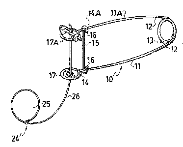
Figure 1 is a æide elevation o the trap with
the safety link in position.
Figure 2 is an enlarged isometric view of the
.
~; eye loops o~the trap in the "set" posltion.
: :
Figure 3 i9 an enlarged isometric view of the
trigger plate per se.
., . .. : ~ :
~` `. : ." ; ,: .
,, :
` :` '` ' `` ' -~

Figure 4 is a section along the line 4-4 of
Figure 3.
Figure 5 is a top plan view of the trigger
plate and trigger block in position.
Figure 6 is an isometric view of one of the
cotter pin attachment blocks.
In the drawings like characters of reference
indicate corresponding parts in the different figures.
DETAILED DESCRIPTION
_. .
Proceeding therefore to describe the invention
in detail, reference shoula be made to the drawings in
which 10 illustrates the trap generally which consists of
two arms 11 and llA made of spring steel and joined at
the inner ends 12 thereof by means of a hairpin spring 13
which normally urges the distal ends 14 and 14A apart.
A safety link 15 is provlded having hooks 16 on
each end and which engages over the arms 11 and llA
~adjac~ent the distal ends thereo~ for transportation,
storage and settlng purposes.
~ Each distal end 14 and 14A is provided with an
; eye loop 17 and 17A respectively shown in enlarged form
in Figure 2.
The eye }oop 17 is provlded~with a semi-circular
disk 18 which is secured as by welding or other means, to
~."" :
,
: . ., ,, ., : : .:
. . . ~ . ..

and across the ba~2 19 of thi~ eye loop. This semi-
circular disk 18 is provided wit~ a free edge 20 having a
slot 21 formed therein intermediate the ends of this free
edge and defined by the vertical sides 22 formed by
removing a rectangular portion therefrom, said slot
terminating in a closed base 23 as clearly shown.
Figures 3, 4 and 5 show that the outer ends of
these sides 22 are bent slightly outwardly or away from
the other eye loop 17A, the purpose of which will herein-
after become apparent.
A snare loop assembly 24 is provided of snare
wire having a freely sliding snare loop 25 formea on a
standing part 26. This standing part is provided with a
distal end portion 27 which passes through the eye 17 and
also through the lot 21 in the semi-circular plate or
disk 18.
; It then passes through the other eye loop 17A
and through a cotter pin assembly collectively designated
:
28 secured across thls eye~loop, terminating in a distal
end 29 upon which a ferrule or stop 30 is provided.
The cotter pin assembly consists of a cotter
:
pin 30 having a head 31, and a spring pin closure 32
engageable through~an aperature formed in the di~tal end
of the cotter pin 30.
'

9~
This cotter pin is secured to the eye by blocks
32 which are aperat~d as at 33 to allow the cotter pin
30 to pass therethrough. Drillings 34 at right angles to
the aperatures 33 engage the opposite sides of the eye
loops 17A as clearly shown.
The distal end portion 27 of the snare cable
passes through an aper~ture 35 in the cotter pin 30 and
the snare wire is retained by the stop ~errule 30 as
hereinbefore described.
~ ot illustrated i~ a stop on the snare loop
limiting the smallest si~e that the loop can form thus
preventing smaller animals than desired from being
trapped by the device.
In operation, the safety link 15 is engaged
around the arms to hold the loops 17 and 17A in adjacent
position as clearly shown.
A trigger blocX 36 is secured to the snare
cable spaced inwardly from the distal end thereof and is
engaged in a position æpanning the slot 21 and outboard
of the semi-circular disk 18. When the safety link is
removed, the spring urges the arms apart and these are
restrained by the ferrule 30 on the one side and the
trigger block 36 on the other.
The snare loop is set to the desired diameter
, ~
: :
~` ,,' :

~L2~ 4~
and the trap is located in the chosen position.
An animal large enough to spring the trap,
engages it~ head through the snare loop 25 until the
shoulders thereo~ are restrained by the snare loop. This
movement disengages the trigger block 36 from the sides
of the slot thus releasing the trap and in this connec-
tion the aforementioned inclination of the sides 22 pro-
vides a slightly positive set to the trap thus preventing
inadvertent disengagement by a smaller animal passing
through the snare loop. -
The release of the trap enables the heavy duty
hairpin spring 13 to move the arms apart rapidly where-
upon the eye loop 17 engages the snare loop and tightens
same and at the same time strikes the animal a severe
blow in the neighborhood of the head, both of which cause
a humane killing of the animal.
Since various~modifications can be made in my
lnvention as hereinabove described, and many apparently
~widely different embodiments of same made wlthin the
~::spirit~and scope of;the claims wlthout departing from
such splrit and 6cope, it is lntended that all matter
contained in ~the~ accompanying ~specification shall be
interpreted aB illustratlve~ only and:not in a limlting
sense. ~ ~
,
,~ ., ~ ' ' :
' ' "' :'. ~" "'' ' . ~ ' ' ' . ' ',, ' ` :
: . '' .. ~ '' '
': :, ` ' -: ~' ,, .'' , ,.
, ., : :.'' . `
. . '`': '`
.. ' ' '' :'" ` .... , `' ':' '

Dessin représentatif
Une figure unique qui représente un dessin illustrant l'invention.
États administratifs

2024-08-01 : Dans le cadre de la transition vers les Brevets de nouvelle génération (BNG), la base de données sur les brevets canadiens (BDBC) contient désormais un Historique d'événement plus détaillé, qui reproduit le Journal des événements de notre nouvelle solution interne.

Veuillez noter que les événements débutant par « Inactive : » se réfèrent à des événements qui ne sont plus utilisés dans notre nouvelle solution interne.

Pour une meilleure compréhension de l'état de la demande ou brevet qui figure sur cette page, la rubrique Mise en garde , et les descriptions de Brevet , Historique d'événement , Taxes périodiques et Historique des paiements devraient être consultées.

Historique d'événement

Description Date
Inactive : Périmé (brevet sous l'ancienne loi) date de péremption possible la plus tardive 2007-05-15
Inactive : CIB de MCD 2006-03-11
Accordé par délivrance 1990-05-15

Historique d'abandonnement

Il n'y a pas d'historique d'abandonnement

Historique des taxes

Type de taxes Anniversaire Échéance Date payée
TM (catégorie 1, 8e anniv.) - petite 1998-05-15 1998-05-13
TM (catégorie 1, 9e anniv.) - petite 1999-05-17 1999-05-06
TM (catégorie 1, 10e anniv.) - petite 2000-05-15 2000-05-15
TM (catégorie 1, 11e anniv.) - petite 2001-05-15 2001-03-21
TM (catégorie 1, 12e anniv.) - petite 2002-05-15 2002-05-01
TM (catégorie 1, 13e anniv.) - petite 2003-05-15 2003-05-06
TM (catégorie 1, 14e anniv.) - petite 2004-05-17 2004-05-06
TM (catégorie 1, 15e anniv.) - petite 2005-05-16 2005-05-05
TM (catégorie 1, 16e anniv.) - petite 2006-05-15 2006-03-21
Titulaires au dossier

Les titulaires actuels et antérieures au dossier sont affichés en ordre alphabétique.

Titulaires actuels au dossier
BRUCE H. BERTRAM
Titulaires antérieures au dossier
S.O.
Les propriétaires antérieurs qui ne figurent pas dans la liste des « Propriétaires au dossier » apparaîtront dans d'autres documents au dossier.
Documents

Pour visionner les fichiers sélectionnés, entrer le code reCAPTCHA :


Pour visualiser une image, cliquer sur un lien dans la colonne description du document (Temporairement non-disponible). Pour télécharger l'image (les images), cliquer l'une ou plusieurs cases à cocher dans la première colonne et ensuite cliquer sur le bouton "Télécharger sélection en format PDF (archive Zip)" ou le bouton "Télécharger sélection (en un fichier PDF fusionné)".

Liste des documents de brevet publiés et non publiés sur la BDBC .

Si vous avez des difficultés à accéder au contenu, veuillez communiquer avec le Centre de services à la clientèle au 1-866-997-1936, ou envoyer un courriel au Centre de service à la clientèle de l'OPIC.

({010=Tous les documents, 020=Au moment du dépôt, 030=Au moment de la mise à la disponibilité du public, 040=À la délivrance, 050=Examen, 060=Correspondance reçue, 070=Divers, 080=Correspondance envoyée, 090=Paiement})


Description du
Document 
Date
(aaaa-mm-jj) 
Nombre de pages   Taille de l'image (Ko) 
Revendications 1993-09-20 5 192
Abrégé 1993-09-20 1 33
Dessins 1993-09-20 1 33
Description 1993-09-20 7 263
Dessin représentatif 2001-08-15 1 10
Taxes 1997-05-06 1 55
Taxes 1996-02-06 1 38
Taxes 1992-03-23 1 43
Taxes 1995-02-27 1 36
Taxes 1994-03-28 1 34
Taxes 1993-03-08 1 53