Note : Les descriptions sont présentées dans la langue officielle dans laquelle elles ont été soumises.
This invention relates to a vacuum system mountable in a
vehicle and used to pick up refuse both out of doors and indoors.
Vacuum systems mountable on vehicles have been known and
used for some time. When mounted to the vehicle they permit the
operator to drive over the area to be cleaned and pick up the
refuse using suction through a pick-up tube.
These vacuum systems have, in the past been plagued by
problems during use.
One of the main problems has been the difficulty of
unclogging the system a~ter it has become clogged. When a piece
of refuse becornes clogged in the vacuum system, it has been the
practice to turn the vacuum system off, disassemble the system at
either the collecting bin or the pick up tube and remove the
clogging piece by hand. This process of unclogging is time
consuming and slows the clean-up process significantly.
A further problem is that there has not been a
satisfactory adjustment means to easily adjust the power of the
suction in the pick-up tube without awkward manual adjustment by
the operator. An easily adjustable suction power means would
permit, for example, the operator to lessen the suction when he is
vacuuming refuse ~rom a flower bed so as to not damage the flowers
without slowing down or temporarily stopping to make that
adjustment.
A further problem with vacuum systems mountable to
vehicles is that the pick-up tube has not been easily
manipulatable about the vehicle. In use, the operator has to
drive the vehicle while directing the pick-up tube and, in the
past, these actions have been difficult to co-ordinate because the
i92~
tube has not been easily directable. The vehicle tended to be too
wide at the ~ront for the operator to reach to both sides from one
seating position and could not be so manufactured. There is a need
for a vehicle and pick-up tube design that can be more easily
directed by the operator.
This invention provides a vacuum system mountable to a
vehicle that permits the operator to unclog the pick-up tube or the
collecting bin without disassembly of the system.
This invention also provides a vacuum system with an easily
adjustable suction means that permits the operator to vary the power
of the suction in the pick-up tube to suit the area that he is
vacuuming.
This invention also provides a vacuum system having an
easily manipulatable pick-up tube.
According to one aspect of the present invention, a vacuum
refuse collector comprises a body, a refuse container mounted on the
body having a refuse chamber,a filter in the refuse chamber of the
refuse container dividing the refuse chamber into a re~use side and a
non-refuse side,a flexib]e refuse collection tube communicating with
the refuse chamber on the refuse side of the refuse chamber, an
atmosphere port, an air velocity increasing means, duct means forming
a first air path from the non-refuse side of the refuse chamber to
the inlet of the air velocity increasing means, through the air
velocity increasing means and then to atmosphere and a second air
path from the air inlet port to the inlet of the air velocity
increasing means through the air velocity increasing means and to the
-- 2
non-refuse side of said refuse chamber and control means for
selectively placing the air velocity increasing means in
communication with the first or second air path to selectively draw
air through said first path to create a suction in the refuse
collection tube or blowing air through said second path to remove
obstructive material from said filter and from said refuse tube aS
required in use.
According to a further aspect of the present invention, a
vacuum refuse collector comprises a road going vehicle, a refuse
container mounted on said vehicle, said refuse container having a
refuse chamber formed therein, a filter dividing the refuse chamber
into a refuse compartment and a non-refuse compartment, a refuse
collection tube having an intake end and a discharye end, the
discharge end communicating with said refuse compartment, air
circulating means connected to said refuse container remote Erom said
refuse collection tube and communicating with the non-refuse
compartment and being operable to selectively withdraw air from or
deliver air under pressure to the non-refuse compartment of the
refuse chamber, such that when air is withdrawn from the non-refuse
compartment, it will draw air through the refuse collection tube into
the refuse compartment of the refuse chamber, through the filter to
the non-refuse compartment and will serve to draw refuse into the
refuse compartment of the chamber and when air is delivered under
pressure, air will pass through the ilter into the refuse side,
thereby cleaning the filter and then through the refuse collection
tubé to unc]og the collection tube as required in use.
'~:
According to yet another aspect of the present invention, a
vacuum refuse collector comprises a wheeled motor driven vehicle
having front and rear ends, said vehicle having a drivers seat
located centrally of said front end, a vaccum refuse coll.ector
comprising a refuse container, a 1exible refuse tube having one end
communicating with said refuse container and an open end for
receiving trash which is to be drawn through the refuse tube into the
refuse container, a manually engageable handle mounted on said refuse
tube so as to be accessible to an operator seated on said driver's
seat, means for drawing air through said refuse tube into the refuse
container, a boom mounted on said vehicle for supporting said refuse
tube, said boom comprising a fixed arm which is mounted on the
vehicle and having a distal end which.is located directly above the
driver's seat and a movable arm which has a proximal end pivotally
mounted on the distal end of the fixed arm for movement in a
generally horizontal plane about a first axis which is substantially
vertically oriented and a distal end which extends outwardly with
respect to said front end of said vehicle, means for connecting said
distal end of said movable arm to support said refuse tube adjacent
the open end thereof, said movable arm being free to swing about said
first axis in a horizontal arc by manipulating said handle when
seated on said driver's seat to locate the refuse tube as its open
end is moved in a horizontal path from one side of the vehicle,
around said front end of the vehicle and to the other side of the
vehicle.
The invention will be fully understood after reading the
following description in conjunction with the drawings in which:
Fi~ure 1 is an illustration of a vehicle with a vacuum
system made in accordance with present invention installed thereon;
Figure 2 is an illustration of the vent means used to
exhaust air from the collecting bin of the vacuum system;
Figure 3 is an illustration of the vacuum system motor, air
passageways and the foot pedal control means for deflecting the air
in through the passageways to achieve the several modes of operation
of the unit;
Figure 4 i.s an illustration of the fan that is driven by the
motor to increase the velocity of the air and create the vacuum for
picking up refuse and for clearing the vacuum line o~ obstruction;
Figure 5 is an illustration of the path of travel of the air
during the vacuuming process to create suction and deposit refuse in
the collecting bin;
Figure 6 is an il.lustration of an alternatlve head assembly
for the vacuum apparatus designed for a different filter construction;
Figure 7 is an illustration of the filter for Figure S used
to prevent refuse from reaching and clogging the fan or motor of the
vacuum system;
Figure 8 is an illustration o~ the mounting of the
collecting bln in the vehicle;
Figure 9 is an illustration of the bracket used to
support the collecting bin on the vehicle; and
Figure 10 is an illustration of the mechanism for tilting
the collecting bin.
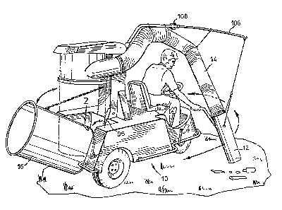
Referring to the drawings, Figure 1 shows a vacuum system
mounted on a three wheeled vehicle 10 driven by an operator. The
operator drives the vehicle over the area to be vacuumed and
directs hand controlled nozzle 12 of the pick-up tube 14 at the
refuse. The vacuum system provides suction through the pick-up
tube to draw refuse into the pick-up tube and deposited it in the
collecting bin 16 o the vacuum system.
In operation, the collecting bin 16 is mounted vertically
as illustrated in broken lines in Figure 1 and as in Figures 5 and
8.
The vacuum system includes a motor-driven fan 18 that
causes the air in the pick-up tube to move at a velocity
suficient to create suitable vacuum to achieve the necessary
power to pick up refuse as required. A velocity of about 150
miles per hour in an 8 inch diameter pick-up tube ~ives ample
pick-up force. I~ the device is to used for sweeping, a reduction
of tube size to six inches for the same motor would increase
velocity and give higher vacuum. Motor speed also increases
vacuum. These are well understood and adjustable in the art. As
will be explained this velocity can be decreased down to zero and
reversed in direction with this invention~
Referring to Figure 5, which shows the air path circuit,
two different conditions achieving two different directions of air
flow in the pick-up tube are illustrated. The first direction
shown by solid line arrows, results when the vacuum system is set
up and working with the baffles 20, 22 and 24 as shown in solid
lines and results in the creation of maximuln vacuum suction at the
open end of the nozzle 12 of the pick-up tube. The second
direction shown by broken line arrows, results when the vacuum
system is set up and working with the baffles 20, 22 and 24 as
shown in the dotted lines, and results in the blowing of air out
of the open end of the nozæle 12 of the pick-up tube 14.
In the solid line and solid arrow vacuuming mode of
operation, the air is driven upwardly of duct 26 by the
motor-driven fan 18. The upwardly driven air travels up the
vertical passageway 26 to exhaust passageway 28, and out the
exhaust port 30 to atmosphere. In this mode, the upward movement
of the air through passageway 26 pulls air from the atmosphere
through the open end of the nozzle 12, pick-up tube 14, through
port 34 of the pick-up tube to the pick-up bin 1~, through the
filter 36, through passage 38 past baffles 20, 22, and 24 to the
inlet 40 of fan 18.
Thus, air travels in through the pick-up tube 14, into
the refuse bin 16, through the fan, upwardly from the fan to the
exhaust port and atmosphere. This is the full suction Inode of
operation that gives maximum vacuum pick-up at the nozzle 12 and
is used to pick-up heavy refuse as illustrated in Figure 1 and
Figure 5. Refuse does not pass through the filter and is
deposited in the collection bin 16 as shown in Figure 5.
There are situations in use when the air passage becomes
clogged. For instance, an object becomes clogged in the pick-up
tube or a piece of paper covers the filter. Air suction through
the pick-up tube is reduced or prevented and vacuum pick-up is
. . ,~, .
.
3~
ineffective. The object must be removed. This vacuum system
provides an easy way of removing the object by reversing the
direction of the air travelling through the filter or pick-up tube
to dislodge the oEfending object into tlle collecting bin or out of
the open end of the noæzle of the pick-up tube.
To achieve this reversal of flow one operates the baffles
20, 22 and 24 from the solid line position to the broken line
position as illustrated in Figure 5.
When the Ean operates with the baffles in the dotted line
positions, air is drawn into the fan from atmosphere through port
42, past open baffle 24 to the fan inlet. Closed baffle 22
prevents it from travelling up passageway 38. From the outlet of
the fan the air travels past baffle 20 through the opening between
passageways 26 and 38, into passageway 38, through the filter 36,
and through the pick-up tube 14 to atmosphere. The velocity of
the air is the result of full operation of the fan and it will
clear clogging of the filer or clogging of the pick-up tube.
Thus, as the reverse Elow air moves through the filter
and out the pick-up tube it removes the object that had been
blocking the suction either by carrying the object out to
atmosphere through the pick-up tube or by pushing the object
downwardly into the collecting bin. This is the full blowing mode
and it is used to clear the system after it has become clogged
either at the filter or within the pick-up tube.
The full vacuum force of the fan 18 is designed to
pick-up heavy objects such as bottles, packages, etc. One often
encounters situations when this force is too great and would prove
destructive. For example, if one wants to remove a piece of paper
beside a flower in a flower bed. Full force would pick-up the
paper but it would also pick up the flower. This invention
permits one to conveniently remove the paper without disturbing
the flower by reducing the vacuum force. This is done by
operating the foot pedal ~2 which will be described later.
Variations of strength of the suction mode and blowing
mode are achieved by arranging the positions of the baffles 20, 22
and 24 between their two extreme positions shown in Figure 5. For
instance, assume that the extreme suction mode is in operation and
that the baffles are positioned as shown in solid line position of
Figure 5 with the air was travelling in the direction as shown by
the solid arrows. Suction or pick-up force is maximum but it can
be .softened by moving the baffles 20, 22 and 24 slightly toward
the dotted line positions. In these positions less than all of
the air passing through the fan comes from the pick-up tube with
the result that the air velocity in the pick-up tube is reduced.
This reduces the pick-up force of the pick-up tube.
The full blowing force is achieved with the baffles in
the dotted line position. This can be reduced by tilting them
towards their solid line position. There is a cross over position
in between where there would be no velocity in the pick-up tube in
either direction.
An operator having a means to orient the baffles to any
degree between their two extreme positions is able to achieve any
degree of suction from zero to Eull suction and any degree of
blowing from zero to full blowing. This device has such an
adjustment means.
Figure 3 is an illustration of a foot control lever
_ ,,~ _
:. ....
~2~9;~
mechanis~ for operating the baffles 20, 22 and 24 as described.
In this illustration the baffles have been illustrated in their
respective solid line position of Figure 5. The baffles 20, 22
and 24 are each mounted on a shaft 44, 46 and 48 that is
journalled in the passageways to permit the operation as described.
Each of the shafts 44, 46 and 48 has a crank arm 50, 52
and 54 respectively rigidly secured to its free end. When the
baffles assume the solid line position of Figure 5, the
disposition of the cranks is illustrated in Figure 3. The free
end of each of the crank arms 50, 52 and 54 is pivotally connected
to an operating lever 55. Shaft 48 has in addition a crank arm 56
secured thereto at its free end. The free end of crank arm 56
pivotally connects with a connecting rod 58. Numeral 60 refers to
a mounting bracket for shaft 48 within which the shaft can rotate.
It will be apparent that by reciprocating connecting rod
5~ to carry its free end to the right as illustrated in Figure 3
that the crank arm shafts 44, 46 and 48 will simultaneously rotate
to carry the bafEle 24 in a counter-clockwise direction, baffle 22
in a clockwise direction and baffle 20 in a clockwise direction.
In the case of each baffle this is movement from the solid line
position of Figure 5 towards the dotted line position of Figure
5. It will be apparent that by reciprocating the cor.necting rod
58 one can move the baffles between the solid line position and
the dotted line position at will.
The reciprocating movement of the connecting rod 58 is
controlled by a foot pedal 62 which is mounted at the upper end of
a lever 64. Lever 64 is pivotally mounted in brackets 66 on the
body of the vehicle 10 so that the free end of the lever can be
_,~ _
~7
moved in the directions of the arrow 68 by pressure on the foot
pedal.
A link 70 pivotally connects the free end of lever 64
with the free end of a lever 72. Lever 72 is mounted for swinging
movement in brackets 74 on the body of the vehicle and its free
end pivotally connects with the connecting rod 58.
It will be apparent that by swinging the lever 6~ within
its mounting 66, the free end of the lever 66 swings in an arc 66
and the movement is transmitted through link 70 and link 72 to
reciprocate the connecting rod 58 whereby to operate the crank 56
and achieve baffle operation as described.
Springs 76, compressed between the body 10 of the vehicle
and the foot pedal 62, maintain the foot pedal in a position that
keeps the lever 64 in a position that results in the dampers being
close to the solid line position of Figure 5. As a matter of
adjustment it is sometimes desirable to have the springs adjusted
so that the normal position is slightly towards the dotted line
position of Figure 5 and the normal suction is something less than
maximum. This adjustment gives the operator the opportunity of
increasing normal operating vacuum pick up if necessary to pick up
a heavy article.
The operator can move the levers by depressing either end
of the foot pedal. Thus from the normal position he can increase
suction by pressing it somewhat. By the same token he can reduce
suction and carry it over to the blow out position to clear the
tube by depressing it in the other direction.
The foot pedal 62 is located conveniently for operation
by the operator when he sits in the control seat o the vehicle.
. . .
~; ~ ` ' '
. . . .:
In Figure 3 the portion of the vehicle upon which the
bracket 74 and brackets 66 are mounted has been indicated by the
numeral 10, the number assigned to the vehicle in specification.
Numeral 78 refers to the engine for the vehicle. Fan 18 is
operated directly from the drive shaft of the engine of the
vehicle. The engine operates at a substantially constant rate of
speed and transmits power to the wheels through a standard
hydraulic transmission as is well known for this type of vehicle.
The collecting bin 16 has a flexible plastics bag liner
80 so that when the bin is full of refuse, the refuse can be
removed from the bin by removing the liner.
In this respect, the refuse bin is mounted on the machine
so that it can be moved between the solid line position of Figure
l where it is in sealing relation with the machine and the dotted
line position of Figure 1 by operation of lever 96. The dotted
line position is the operative position as illustrated in Figure 5
but the removal position has been illustrated in Figure 1 in solid
lines to illustrate the removal function.
Fi9ures 8 and 9 illustrate the mechanics of the mechanism
for moving the container between the sealing position and a
position from which it can be emptied. The container has a pair
of brackets 82, one at each side and welded to its bottom. A
shaft 84 extends between the two brackets. The shaft 84 sits in
notches 86 of the arms 88 of a mounting assembly generally
referred to by the numeral 90 in Figure 9. The mounting assembly
has a shaft 92 that is journalled for pivotal movement in the
frame of the vehicle 10 as illustrated in Figure 8~ A crank 94 is
rigidly mounted on the end of the shaft 92. It will be apparent
~L2~
that rotation oE the cr~nk 9~ will caus~ rotation of tile arms 88
of the mounting assembly 90 to move the bin, the shaft 84 of which
is journalled in the notches 86 of the arms 8~. This allows the
bin to drop downwardly Erom the sealed position.
An operating crank 96 mounted on a bracket 98 which is in
turn mounted on the frame of the vehicle 10 can be rhanually
pivoted about its pivotal mounting 100 to carry the free end
thereof in an arc. The free end of crank 96 pivotally connects
with a link 102. Link 10~ pivotally connects at its other end
with the crank 94. Thus, the initial dropping of the bin 16 is
controlled by manually operable crank 96.
In Figure 8 the bin 16 is illustrated in the operative
position. The weight o~ the bin is supported in the notches 86 of
the arms 88 of the mounting assembly 90 and exerts a force in a
clockwise direction on the mounting assembly about its shaft 92
which is pivoted in the erame as at 93. The pivot point 103
between links lO2 and crank 96 is above the level of pival points
105 and 100. A stop 107 on the frame limits the movement of lever
96 in position illustrated in Figure 8 when the refuse container
is in position as illustrated. Thus the weight o~ the container
urges the handle 96 against a stop when the refuse container is in
the operative position and its edges are sealed against the
machine.
To release the container one pushes the handle 96 in a
counter clockwise dirsction to overcome the weight of the refuse
bin to carry the pival point 103 below the line between points 105
and 100. When this is done the weiyht of the container is free to
turn crank 94 in a clockwise direction to permit the platform 90
~'3
: . .
~ ~i9~1~
to initially drop. One then manually swings the bin rearwardly to
the position shown in Figure l as limited by the check chain 17.
To reinstall the bin to the position of Figure 8 one hand
tilts the bin to an upright position and then turns lever 96 in a
clockwise direction to reinstate the overcentre position of pival
point 103 and seal the bin in position.
Figure 2 is a detail of a portion of the bottom of the
collecting bin 16. When a bin has been remounted with a fresh
plastics insert bag 80, the insert bag probably does not adhere
tightly to the sides of the bin.
The plastics bag is relatively impervious to air and in
this condition it would likely be sucked against the screen to
plug the screen under normal conditions of vacuum operation. One
needs to force the bag against the sides of the bin and evacuate
the air in the bin that is between the bag and the bin. This done
by Eorcing air into the bag. As air is Eorced in the bag the air
between the bag and the bin is evacuated through holes 112 as
resilient gasket l10 yields. When pressure in the bag is released
the gasket 110 closes. It is a check valve arrangement.
To achieve air pressure in the bag, one operates the fan
to blow air out the nozzle 12 and plugs the end of the nozzle by
pressing it against the ground. This forces the air to blow back
into the bag and force the bag against the sides of the collecting
bin.
Figure 6 shows an alternative construction for the upper
portion of the vacuum system showing an alternative type of filter
element. The filter of Figure 7 is formed with an entrance that
communicates with the entrance to the passage 38. The filter
/~
element 35 of Figure 6 has a less complicated fit at the upper end
of the head 37 of the machine where it communicates with the
passage 39 which is the equivalent of the passage 38 of Figure 5.
otherwise the arrangement is similar. Passage 27 corresponds to
passage 26 and passage 29 corresponds to 28 in Figure 5.
In use, the operator of the vehicle maneuvers the vehicle
to the location of refuse as illustrated in Figure 1. He manually
manipulates the location of the rigid nozzle 12 at the end of the
Elexible hose 14. It will be apparent that by reason of the
suspension oE the hose and the narrow front end of the vehicle he
can direct the nozzle to either side of the vehicle with equal
facility. In this connection it will be noted that the nozzle is
suspended from a spring suspension boom 106 that can be pivoted
around the vehicle with the biforcated bracket 108. The
combination of the narrow front width and the swingable boom
greatly increase the flexability of the unit. The abillty to move
completely around the vehicle and to pick up refuse on both sides
is an advantage of the boom suspension of the manually manipulated
noz~les.
As indicated the operator picking up heavy refuse such as
bottles, newspapers would use substantially full vacuum and the
baffles would be close to or at the solid line position
illu~strated in Figure 5. If he should require less vacuum he
would by manipulation of the foot pedal 62 cut the vacuum in the
tube by tilting the levers towards the dotted line position.
If the system should become clogged in any way it is a
simple matter to operate the Eoot pedal to cause the baffles to
move to the dotted line illustrated in Figure S. This causes the
~X~i9Z~
air to blow through the system in the opposite direction and clear
the obstruction. Thus it is not necessary to stop the machine in
the case of obstruction. From the explanation given above of the
means for emptying the can it will be appreciated that emptying
the can is merely a matter of operating the handle lever 96 to
release the collecting bin from the dotted line position of Figure
1 and swinging it to the solid line position of Figure 1 from
which the plastics bag can be removed and a new one inserted for
refittiny to the machine. It is replaced to operating position by
operation of handle lever 96.
Embodiments of the invention other than those illustrated
will be apparent to those skilled in the art. For example,
different ways of achieving the blow back and variations in vacuum
pressure are contemplated. Prime requirement is that one have
some means for varying the velocity of the air and changing the
direction of the air in the pick-up tube.