Note : Les descriptions sont présentées dans la langue officielle dans laquelle elles ont été soumises.
1%&~7~
- 1 - 4881-282
Thls inven-tion relates to the measurement of a
dimension of non-metallic material molded bodies having a shape
that ls impossible to measure by usual means, such as vernier
calipers, micrometer calipers and the like.
As a means measuring a dimension, particularly
thickness, of a body, vernier calipers and micrometer calipers
have been most usually and extensively used. However, as is
easily understood from the general shape of vernier calipers or
micrometer calipers, when the body to be measured is so shaped
that it cannot be interposed between the calipers, the measurement
of the thickness is impossible. Examples of what cannot be
measured with calipers are the wall thickness of the middle portion
of a slender hollow tube, the wall thickness of a closed tip
portion of a hollow tube having a closed end, etc., as the
measuring parts of the vernier calipers or micrometer calipers
cannot be inserted into these tubes.
Incidentally, amongst non-metallic material molded
bodies, ceramic products are generally manufactured by granulating
a starting powder to which is added a bonding agent such as a
binder or the like, forming the thus granulated powder into a
ceramic green molded body, by a molding means such as mold pressing,
isostatic pressing or the like, and -thereafter firing the ceramic
green molded body at a predetermined temperature in an electric
furnace, etc. The dimension of the products is influenced by
conditions of firing which is accompanied by contraction, and the
j conditions of firing are usually constant, so that the dimension of
i.::
i ~
~ ~ .
: ''; '' ' ` '
.
~L2~i~7~
- 2 - 4881-282
the products depends upon -that of the ceramic green molded bodies
in the molding process. Accordingly, precise measurement and
control of the dimension of the ceramic green molded bodies are
very important, in the ceramics manufacture, for lessening dls-
persion of dimension of the products after firing.
Thus, the ceramic molded body before firing is
particularly pertinent to the present invention and herein called
a ceramic green molded body, though the ceramic product after
firing also can be understood to be a kind of a non-metallic
material molded body to which the invention is applied.
In order to measuré the thickness of ceramic green
molded bodies, a direct method as metnioned above has been
generally employed, wherein a measuring implement, such as vernier
calipers, micrometer calipers and the like, is used. However,
as was mentioned hereinabove, when a ceramic green molded body to
be measured is in a form of a hollow open or closed ended tube,
it has been almost impossible to make a measure of the wall thick-
ness of the middle portion or near the closed end portion, due to
the inadequate shape of the vernier calipers or micrometer calipers.
Further, since ceramic green molded bodies are generally brittle
and fragile wherein particles of the material powder are merely
bound together by the action of a binder, such hollow tubular
bodies with a thin wall have frequently suffered impairment, such as
cracks, etc., during the thickness measurement.
Furthermore, like a transparent alumina ceramic
blow-molded part which is used as a light-emitting tube in a high
' ~ .
: , ~ ,, .
~ :., .:, : : .
.. . ..
71~L
64881-282
pressurs sodium-vapor lamp, etc., when the hollow tube is in a
bulbed form, with a middle portion having a diameter (about 5 mm)
larger ~han that of its end portion (about 3 mm), the vernier
calipers cannot be inserted thereinto, so that the measurement of
the wall thickness of the midd:Le portion (about 0.2 mm) has been
absolutely impossible. Besides, it is very important for ceramic
products having such a form, in view of their use, to have a small
dispersion of wall thickness, particularly, at the middle portion
thereof.
On the o~her hand, al~hough ~here has been an indirect
method for measuring ~he thicknes~ by using ultrasonics, yet
attenuation of the ultrasonic wave is generally 50 rapid due to
the fragility and softne~s,.as mentioned above, of the ceramic
green molded bodies immedia~ely after molding, that thickness
measurement with a hlgh precision has been diffi~ulk.
An object of the present invention is to provide a
measuring method whereby a measure can be simply made of the
thickness of a non-me~allic material molded body ~o shaped that
the measurement has been difflcul~ by a conventional means such aæ
vernier calipers, micrometer calipers or the like.
The lnvention provide3 a method of measuring the
thlckness of a ceramic tubular molded body having a closed end,
comprising: contactlng a measuring probe with the outside surface
of the ceramic tubular molded body immediately after molding,
which ceramic tuhular molded body temporarily supports inside
thereof a metallic mold used in the molding; and measuring tha
,
:` : `
. .. :
~2~7~
648~1-282
thickness of said ceramic body immediately after molding utilizing
an electromagne~lc combination of an alternating magne~ic field
generated by sald probe with said metallic mold, said al~ernating
magnetlc field having a frequency ranging from 1 KHz to 100 KHz.
i:
~.~
~ .,
i . ~
¦~ ~ 3a
~,
~ . .. , .- . .. .
~;26~7~L~
- 4 - 4881-282
The method of the present invention can determine
with a high precision, particularly in a molding step of ceramics,
the thickness of a portion of a ceramic green molded body which
has been difficult to measure by a conventional means. In this
case, an electrically conductive, metallic mold which is sub-
stantially in close contact with the ceramic green molded body
immediately after molding is used as the metal.
The present invention defined above is effective for
measuring thicknesses of a body consisting of a non-metallic
material and having a hollow shape, etc. This invention is
theoretically not applicable to a body consisting of a metallic
material for the reason that will be explained hereinafter. As
a non-metallic material, mention may be made of organic materials
such as plastics, etc. and inorganic materials such as ceramics,
etc. Further, a body consisting of a non-metallic material includes
for example a molded body, generally the material of which has been
~; processed by a certain means, irrespective of whether it is an
intermediate product in a manufacturing process or a final product.
The principle applied to the present invention is as
follows. It is widely known that, when a good conductor, such as
~; a metal, etc., is located in an alternating magnetic field, an
eddy current corresponding to the alternating magnetic field is
induced in the conductor. A part of energy of the alternating
magnetic field is finally converted, in the good conductor, into
thermal energy which is eventually lost. In general, the extent
of the loss depends on the frequency of the alternating magnetic
: ~
-, ~
~; . . .
121~7~1
- 5 - 4881-282
field, the intensity of the magnetic field and the electric con-
ductivity of the good conductor.
In contrast, in the case of an electric insulator
which does not disturb the alternating magnetic field, the loss
is substantially negligible. Most non-metallic materials, such as
plastics, ceramics and the like, are electrically insulative.
Since usua] ceramic green molded bodies are also electrically
; insulative, they cause no losses. Further, even when the ceramic
green molded bodies are semi-conductive, they can be relatively
regarded as electric insulators, because their resistivity near
room temeprature is lxlO0~lxlOl ~-cm or more which is larger a
factor of 106 to 107 or more, than the figure for metals, i.e., good
'" conductors, which generally have a resistivity of the order of
lxlO-6 Q-cm.
The invention is illustrated diagrammatically in
, the following drawings wherein:
i~ Figure l is a sectional view illustrating schematic-
~..
:~ ally the thickness measurement, according to the present invention,
of a ceramic green molded body;
0~ ~ Figures 2Aj 2B and 2C are sectional views, illust-
~; rating successive stages in the preparation of a test specimen;
Figure 3 is a graph~showing the relation between
the thickness of a molded body and displayed voltage of a bridge
circuit, using the test specimen of Figure 2; and
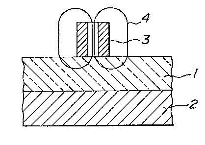
Figure 4 lS a sectional view showing another test
specimen.
~2697~L
- 6 - 4881-282
In a molding step of a normal ceramic item,as shown in
Figure l, a measurlng probe 3 generating an alternating magnetic
field 4 is brought into contact with a ceramic green molded body l
which is substantially in close contact with a metallic mold 2
immediately after molding. Since the materials of the metallic
mold 2 and ceramic green molded body l are usually kept unchanged
; and, besides, the intensity and frequency of the alternating
magnetic field 4 generated by the probe 3 can be kept constant, the
loss of the alternating magnetic field 4 depends on the distance
between the probe 3 and the metallic mold 2, i.e., the thickness
of the ceramic green molded body l. The thicker the green molded
body l is, the less the loss is, and the thinner, the larger the
loss is. Though this relation between the loss and the thickness
is generally non-linear, if the relation has been found in advance,
the thickness can be obtained from the loss amount.
The probe 3 that generates the alternating magnetic
., ~
, field is basically composed of a so-called solenoid coil. The
solenoid coil may have a magnetic core. In order to attain a cIose
-
~ electromagnetic coupling of the alternating magnetic field 4 with
: :
the metallic mold 2, it is desired that the central axis of
.~ :
~; symmetry of the coil be aligned perpendicular to the surface of
~: :
the metallic mald 2. If the relation between the loss and the
thlckness has been found in advance, the surface of the metallic
mold 2 may not necessarily be planar, and may be a curved surEace.
However, in order to attain a close electromagnetic coupling, it is
important that the ceramic green molded body l be not too thick in
.:: :
- .
':~,.`.`; ~ ~
~'': `; ` ', :' ~`' ' ' ' '': ;i' '': . ~.` " ' : , `:`: '
~697~
- 7 - 4881-282
relation to the diameter of the solenoid coil. Generally, a
thickness approximately not larger than the diameter of the coil is
preferably measured.
Though the invention as described above relates to
ceramic green molded bodies, the principle of the invention, as it
utilizes a condition wherein a metal is in close contact with one
side of a non-metallic material molded body the thickness of which
is to be measured is theoretically applicable to any non-metallic
material molded bodies, such as ceramic fired bodies or organic
~i~ 10 material molded bodies such as plastics, etc., if a metal, for
example, a liquid metal such as mercury, is in close contact
therewith.
A measure of the loss of the alternating magnetic
field, i.e., the loss caused in the coil, is generally made by
composing an A.C. bridge circuit including the coil as a component
~i thereof. In the A.C. bridge circuit, the loss, i.e., a variation of
impedance of the coil, is relatively easily detectable, as a
variation of voltage, by modifying a known electronic circuit. The
~` frequency of the alternating magnetic field, i.e., the frequency
of the bridge, ls preferably l KHz~lO0 KHz and, more preferably
~lO KHz~30 KHz. The reason why the frequency preferably ranges
between l KHz and 100 KHz, is because, if less than l KHz, the
variatlon of impedance is so small that the measurement error
increases and, lf more than lO0 KHzj the measurement error also
increases due to a stray capacity of the A.C. bridge circuit. The
reason why the range from lO KHz to 30 KHz is more preferred, is
,~ `,
97~L
- 8 - 4881-282
because each of the error factors descrlbed above decreases in this
range.
The present invention will be further explained by
way of examples.
Example l
The present invention was applied to a thickness
measurement of a zirconia green molded hollow tube having a closed
end, in a moldingstep of a zirconia ceramic. This zirconia green
molded body i9 fired and employed as a solid electrolyte oxygen
sensor of an oxygen densitometer. For the solid electrolyte
wherein ions move to the direction of the thickness, control of
the thickness is particularly important.
As shown in Figure 2A, a cylindrical rubber shell 7
was fixed on a stainless steel rod-like metallic mold 2 having a
portion arranged for contact with a granulated powder, this portion
, 1 - .
being l5 mm in diameter and 385 mm long and the space between the
rubber shell 7 and the metallic mold 2 was filled with zirconia
~; granulated powder 5. Then, as shown in Figure 2B, a rubber cap 6
was ixed, upper and lower jolnt parts of the rubber shell 7 were
sealed with a vinyl tape (not shown), etc. wound thereon, to pre-
vent infiltration of water under pressure, and molding was carried
out wlth a pressure of 2,000 kg/cm2, 1n an isostatic pressing
machine. Next, as shown in Figure 2C, the rubber cap 6 and the
rubber shell 7 were removed and a measuring probe 3 of 5 mm in
diameter was contacted with a side surface of the resulting exposed
zi;rconia green molded body 8. The displayed voltage of a bridge
.. " ~
~:: :: ~ ::
~ i :
- ~L2697~L
- 9 - 4881-282
circuit electrically connected with the measuring probe 3, was
read. Thereafter, the zirconia green molded body 8 was broken
down, and the thickness of the portion that the probe was contacted
with, was measured with micrometer calipersO The above procedure
was repeated 25 times to find a relation between the thickness of
the zirconia green molded body 8 and the displayed voltage of the
bridge circuit. Thus, as shown in Figure 3, a good linear
relation was obtained in the range from 0 mm to 3 mm. The bridge
circuit used in this example was added with a non-linearity
correction circuit, and the frequency was 20 KHz. The thickness
of the zirconia green molded body 8 may be usually controlled to
2 mm + 0.1 mm and, according to this embodiment, the measurement
had a sufficient precision and was practical.
Example 2
The present invention was applied to a thickness
measurement of a hollow tubular alumina ceramic fired body.
As shown in Figure 4, a hollow alumina ceramic
. .
fired body~9 having 20 mm outside diameter, 15 mm inside diameter
and 200 mm length, was stood perpendicularly on a base 11 and,
~from the upper opening end, a liquid metal i.e. mercury 10, was
poured into the hollow. A measuring probe 3 having 5 mm diameter
was aontacted with a middle portion of the outer surface of the
alumina ceramic fired body 9, and the displayed voltage of a bridge
circuit was read. Then,~the alumina ceramic fired body 9 was
broken down, and the~thickness of the portion that the probe was
contacted with, was measured with micrometer calipers. A relation
, ~
between the thickness of the fired body and the displayed voltage
:~ ." ~: ~
71~
- lO - 4881-282
of the bridge circuit, accorded with the straight line shown in
Figure 3 and was practical.
Example 3
;~ The thickness measurement as described in Example 2
was applied to a ceramic green molded body of a closed ended
tubular form for a ~-alumina solid electrolyte, and also to a:
ceramic green molded body for a hollow tubular alumina porous
ceramic filter for liquid or gas filtration. Results similar to
that shown in Figure 3 were obtained.
,~
::
: :
:
~ " ~ :
~ r~. : :