Note : Les descriptions sont présentées dans la langue officielle dans laquelle elles ont été soumises.
ROCESSI~G_CROP MATERIAL
This invention relates to the processing of material
and in particular to a method and apparatus for
compacting mate~ial 9 such as straw and other loose
fibrous material, into discrete blocks or ~riquettes.
The invention has application to the disposal of crop
residues such as stra~ resultillg from the harvesting
of grain. It has been proposed to bale such residues
into bloc~s or bales the density of which can be high
or lo~, for use as feed, bedding or ~uel . However
conventional baling equipme~t is only able to
provide bales of a density such that a high volume o~
material is required for each unit of heat if the
bales are to be used as fuel. If the crop residue
could be economically compressed to a density
approaching that of say wood a much greater use could be
made of the residue as a fuel.
Hitherto appa~atus has been proposed for producing
high density quantities of stra~ but such apparatus
suffers from ~arious disad~-antages. It is ver}~ bulky
and has a lo~ rate of throughput. The rate of power
consumption is high relative to the throughput -~nd
the stra~ must be chopped into short lengths before
compression ~a~es place. Such prior apparatus
~enerally in~olves the use of a reciprocating ram
2; mo~able a]ong an open-ended cylinder to compress the
ctraw and extrude it.
It has also been proposed to form compressed blocks of
hay from loose hay fed between the meshin~ teeth of a
pair of ~heels but such apparatus is unable to form
bloc~s of sufficiently high density for economic use.
~L;26~
- 2 -
An object of the present invention is to provide a
~ethod and apparatus for compacting or compressing
material to produce high density material in which -
the po~er re~uirements are relatively low.
According to one aspect of the invention a method of
compacting fibrous material includes the steps of
precompressing the material to form a compressed length
of the material, feeding the compressed length to
compacti~g apparatus including a pair of rot~ry
members which define between them pockets in which the
compressed length is received, compacting the material
in the pockets by reducing the si2es of the pockets
progressively as the rotary members are rotated until
the pockets reach a region of maximum compression of
the material, separa*ing the compacted material into
discrete blocks or briquettes and discharging the
blocks or briquettes from the pockets.
According to another aspect of the invention apparatus
for compacting fibrous material comprises precompression
means for compressing loose fibrous material to form
a length of compressed material, compacting means for
compacting the length of material and forming the
material into compacted discrete blocXs or briquettes,
the compaction means including a pair of rotary
members r~tatable about axes inclined relative to one
anoTher, drive means for the rot~ry members9 a row of
poc~ets in which the material is to be received and
compacted, the pockets extending in a ro~ around each
of the rotar~ members, the pockets on one rotary member
defining with the other rotary member spaces in which
the material is received and9 during rotation of the
rotary members, the memberc converging and the spaces
progressively reducing in size until said spaces reach
,~
`~
a mini~um ~ize at which ma~imum convergence occurs
and maximum compaction of the material takes place,
the compaction means further comprising feed ~eana ~or
feeding the compressed length of material to the
pockets and discharge means for discharging compacted
discrete blocks or briquettes of material from the
pockets.
Preferabl~ the poc~ets of each rotary member are spaced
~rom each other alon~ a circular ro~ and the rotary
members are arranged so that the pockets o~ one member
register ~ith spaces between pockets in the row of
pockets Or the other rotary member, and a continuous
row of poc~ets is defined b)7 the rotar7- members,
Con~enientl~ the rotar~- members in the region in which
their maximum convergence arises are closely ~djacent
one ~nother. Said region of maximum con~ergence
preferably lies in a plane coincident ~ith the
intersection of the axes of rotation.
~leans ma be provided ~ngaging the rotar~ members to
resist the tendency of the members to move apart, ~t
least in the position of ma~imum compres~ion Or the
material.
~he discharge means ma~ include a plunger defining a
portion ~f the base of each pocket, the plunger being
mo~-able to~ards the open end of the pocket to e ject
the discrete blocks or briquettes upon the
associated pocket passing the regio~ o~ maximum
converge~c~ 9 during rotation of the rota~- members.
The apparatus of the invention is capable of producing
a continuous flow o~ compressed blocks or bri4uettes
~ -
~L269~8~i
.. ~,
of hi~hly compressed material from ~aid pockets with
relatively low rate of power consumption.
Preferably the precompression means includes apparatus
for forming loose fibrous material into a twisted rope
of compress~d material. ~or example the
precompress~d material, if in the form of stra~, may
be compressed by the precompression means to give a
30:1 t~ 10.1 reduction in ~olurne from a feed of
uncompressed straw. The compaction apparatus ~ay
then pro~ide a ~urther volume reduction of the order
of 3:1 to 5:1 to gi~-e an overall reduction in volume
of the order of 40:1 to 100:1, subject to the initial
bulk density of the material.
~urther features of the invention will appear from
the following description o~ an embodiment of *he
invention given by way of example only and with
reference to the drawingc, in which:-
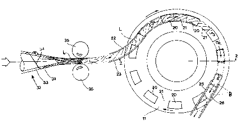
Fig. 1 is a schematic plan ~iew of apparatus rorcompressing crop material into briquettes showing
the lower of two rotary members, precompression means,
and a feed arrangement,
Fig. 2 is a cros~-section on the line 2-2 in Fi~. 1,
showing the two rotary rn~mbers of the compaction means,
Fig. 3 is a cross-section along a circular row of
25 pockels of the apparatus of Figs. 1 and 2 o~er one
segment 3-3 of the rotal~ members, and
Fig. 4 is a cross-section corresponding to that of
Fig. 3 o~er another segm,ent 4-4 of the rotary members.
:- 5 --
Referring to the dr~wings compaction apparatus
includes two rotary members 10 and 11 each rotatable
about an axis 12 a~d 13 respectively, the ~xes lying
in a com~on plane and being inclined at an acute angle
relative to one another. In the illustrated
arrangement the angle between the axes 12 and 13 is
about 10 but this angle can ~ary according to the
diameter of the members, the nature of the crop
material, the degree of compression required and
other factors. For example the angle may lie in
the range of between 5 2~ .
The members 10 and 11 are arranged to be rotated in
the same direction b,~ drive means ~not shown). Such
drive means may be coupled to a shaft 14 ~nd/or 15 on
1~ ~hich the members 10 and 11 are mounted.
In the illustrated arrangement the members 10 and 11
each carry meshing be~el gearing 16 and 17 ~ereby
one member is driven by the other at an identical speed.
~o~-ards the radiall~ outer edge of each of the rotary
members 10 and 11 is arran~ed a row of pockets 19 and
20. The pockets 19 and 20 of each row are spaced ~rom
one another along the row a distance to pro~ide a
spacing 21 between the pockets approximatel~ e~ual
to the length of each pocket as measured along the
circular ro~ of poc~et6.
The pockets 19 of the member 10 are arranged in
relation to the pockets 20 of the member 11 such that
the pockets 19 lie o~-er the spaces 21 between the
pockets 20, and the pockets 20 lie o~er the spaces 21
bet~een the pocket~ 19. Thus the pockets 19 are at
the same spacings and of the same lengths as the
.~
.
~26~
. ---`` :
pockets 20 an~ the pockets 19 and 20 are located
along a row at the same distance from the respective
axes 12 and 13 of the members 10 and 11.
Each of the pockets is of part annular form and the
pockets approximate to a rectangle, as seen in ~ig. 1,
or a square in cross-section; and the pockets taper
towards their base.
Due to the inclination of the members 10 and 11 and
the proximity of $he me~bers~ the pockets, as they
progress along circular paths during rotation of the
members, are moved to~ards and away from each ~ther.
At one side of the members 10 and 11 the pockets 19
and 20 are at a maximum spacing from each other.
At the opposite sîde of the members the pockets are
a close proxi~ity and at a minimum spacing ~rom each
other. In the latter region, i.e. tG the righ~ hand
side as seen in ~igs. 1 and 2 and as sho~ in ~ig. 4 7
the surfaces bounding the inner and outer edge~ of the
pockets 19 and 20 may- be brought closely adjacent to
but not in contact ~ith each other,
It will also be seen from Fig. 2 that the pockets 19
and 20 at their positions Or minimum spacings lie
s~etrically relative to 8 plane X coincident with
the point of intersection P of the axes 12 and 13
and the bases of the pockets are parallel to said
plane X.
The pockets 19 and 20 converge to~ards one another as
they approach their positions of minimum spacing and,
as they converge, material located between the pockets
19 and 20 is co~pressed between a~d into the pockets
until, at the minimum spacing position, substantiallY
~,;
.
~26~
-- 7 --
all the material is located in the pockets in a
compressed condition.
Material to be fed to the compaction apparatus is-in
the form of a precompressed length or lengths L of
fibrous crop material such as straw in the nature of
a t~isted rope of material. The rope is fo~med
from loose straw or other material in a form such as
may be discharged from a combine harvester but it
should not be necessary or desirable that the loose
straw should be chopped into short lengths. The
preco~pressed length L of material may ~e produced by
any con~enient means to achieve precompression of
the material from the loose form to give a ~olume
reduction of the order of 30:1 to 10:1 before feeding
to the compaction apparatus.
In Fig. 1 prec~mpression apparatus is shown
schematically at 32 in which the loose material is
extruded from a cone 31 after being introduced
to~ards the wider end of the cone. A screw member 34
is located ~ithin the cone to define an annular
space 33 bet~een the scre~ member 34 and the cone 31
through which 6pace the material is passed. It will
be seen that the annular space 33 reduces in volume
in the do~mstream direction to cause the material
2; passing therethrough to be compressed. Dri~e means
(not shown) c~uses relative rotation between the
cone 31 and the screw member 34 ~hich under the
action of the scre~ fol~ed on the member 34 causes
the material to issue in a continuous length in
compressed form from the apical end of the cone ~1.
The length of material L is enga~ed bet~een a pair of
dri~en rollers 35 as it issues from the cone 31 to
help draw the material from the end of the oone and
to inhibit rotation of the length L about its
c , .
~_ .
`~ ~2~9~38~;
.
longitudinal axis during its pass~ge through the
rollers 35. Thus the action of the rollers 35 i~
to feed the compressed length of material towar~s the
~ompaction apparatus but in ~o doing the rollers
perform other useful functions. Thus the rollers 35
in drawing the length of material from the cone assist
in the passage of the material throu~h the apparatus 32D
In additicn, by p~e~enting rotation of the length L
of material as it passes between the rollers 35 the
winding or twisting action of the apparatus 32 o~
the length L is enhanced up to the point where the
length is gripped by the rollers.
A similar effect ma) be achieved upon omi-tting the
rollers 35 and relying on the gripping of the length
L by the rotary members 10 and 11 as it is zompressed
in the pockets 19 and 20. As the ~ength L is
gripped in this way it is dra~ out of the cone and
assists in causing twisting about its axis, as
described, up to the point where the length is gripped.
Material ~rom the rollers 35 or direct from the cone
31 is introduced bet~een the members 10 and 11
bet~een curved guide elements 22 and 23 extending
from the region of maximum spacing of the pockets and
along th0 path of the pockets toward.s the region of
minimum spacing of the pockets.
~he length L of maTerial fed to the members 10 and 11
ma)~ be a continuous length or discontinuous
successi~e lengths.
The arrangement of the pockets 19 and 20 and the
degree of compression imparted by ~he rotary members 9
~-hich may be o~ the order Or 5:1, ensures that the
2~8~S
g
individual blocks or bri~uettes B of material formed
in the pockets are automatically severed from o~e
another upon release from the pockets along the junction
bet~een respective pockets 19 and 20 of the members
10 and 11, It has been found that the surfaces 21
on the members between the pockets may be spaced at
said ~unctions, as seen in Fig. 4, a dista~ce d
~ithout preventing the automatic se~ering action
between briquettes B to occur. However, if desired/
means may be provided for cutting through the material
between adjacent briquettes B i~ this pro~es to be
necessary.
After the pockets pass through the region of minimum
spacing between the pockets (Fig. 4) and diverge,
the material in the pockets will expand to project
out of the pockets. As this occurs the briquettes B
are engaged by discharge guides 25 and 26 or other
means, released from the pockets, and diverted from
the rotary members 10 and 11 so that the pockets can.
~0 receive a further charge of material from the feed
means 2Z and 23. In addition each poc~et 19 and 20 may
ha~e a mo~able ~lunger 37 in its base, the plunger
being engaged by a cam (not sho~n) to mo~e the pllmger
into the pocket and push the bri~uette out arter it
ha~ been fo~led, for example as the pocket passes
ber~een the guide means 25 and 26, The plungers 37
may be returned to the bases of the pockets by
engagement ~ith a fresh charge of material to be
compacted,
To counteract the loads on the rotary members tending
to force the members apart3 particularly in the region
of minimum spacing between the members, the members
10 and 11 may be engaged by rollers 28 and 29 mounted
on a frame 30.
,-. ,~; .
lZ69885
..
10 --
The dimensions of the ~otary members, the pockets
and the speed of rotation of the members is
dependent on various factors but to achie~e a
throughput of briquette production in the region
of ten tonnes per hour the briquettes may be
approximately 50 mm wide 70 mm long and 50 mm deep
and the rotary members may have 28 pockets rotating
at about 75 r.p.m. It has been found that ~ith
such an arrangement the briquettes may each ~eigh
about 80 grams.
!. . ,, ~