Sélection de la langue

Search

Sommaire du brevet 1270027 

Énoncé de désistement de responsabilité concernant l'information provenant de tiers

Une partie des informations de ce site Web a été fournie par des sources externes. Le gouvernement du Canada n'assume aucune responsabilité concernant la précision, l'actualité ou la fiabilité des informations fournies par les sources externes. Les utilisateurs qui désirent employer cette information devraient consulter directement la source des informations. Le contenu fourni par les sources externes n'est pas assujetti aux exigences sur les langues officielles, la protection des renseignements personnels et l'accessibilité.

Disponibilité de l'Abrégé et des Revendications

L'apparition de différences dans le texte et l'image des Revendications et de l'Abrégé dépend du moment auquel le document est publié. Les textes des Revendications et de l'Abrégé sont affichés :

  • lorsque la demande peut être examinée par le public;
  • lorsque le brevet est émis (délivrance).
(12) Brevet: (11) CA 1270027
(21) Numéro de la demande: 1270027
(54) Titre français: APPAREIL DE POMPAGE PIEZOELECTRIQUE POUR FLUIDES
(54) Titre anglais: PIEZOELECTRIC FLUID PUMPING APPARATUS
Statut: Périmé et au-delà du délai pour l’annulation
Données bibliographiques
(51) Classification internationale des brevets (CIB):
  • F04B 17/00 (2006.01)
  • F04B 35/00 (2006.01)
  • F04B 43/04 (2006.01)
(72) Inventeurs :
  • ABUJUDOM, DAVID N., II (Etats-Unis d'Amérique)
  • DOUGHERTY, JOSEPH P. (Etats-Unis d'Amérique)
  • STENGEL, KEVIN M. (Etats-Unis d'Amérique)
(73) Titulaires :
  • JOHNSON SERVICE COMPANY
(71) Demandeurs :
  • JOHNSON SERVICE COMPANY (Etats-Unis d'Amérique)
(74) Agent: KIRBY EADES GALE BAKER
(74) Co-agent:
(45) Délivré: 1990-06-05
(22) Date de dépôt: 1986-09-29
Licence disponible: S.O.
Cédé au domaine public: S.O.
(25) Langue des documents déposés: Anglais

Traité de coopération en matière de brevets (PCT): Non

(30) Données de priorité de la demande:
Numéro de la demande Pays / territoire Date
832,227 (Etats-Unis d'Amérique) 1986-02-24

Abrégés

Abrégé anglais


ABSTRACT OF THE DISCLOSURE
A piezoelectric fluid pumping apparatus includes
pumping means for supplying a fluid under pressure and an
energizer arranged in driving relationship therewith. The
energizer includes a generally planar flexure member
having first and second piezoelectric laminates supported
thereon. The flexure member includes a first edge and a
second edge, the edges being resiliently constrained for
substantially preventing longitudinal movement thereof
when an electrical signal is applied to the laminates.
Preferred embodiments of the flexure member include
bimorphous, biunimorphous and quadrimorphous piezoelectric
structures.

Revendications

Note : Les revendications sont présentées dans la langue officielle dans laquelle elles ont été soumises.


Claims:
1. A piezoelectric fluid pumping apparatus
including: pumping means, including a fluid inlet for
filling said pumping means with fluid and a fluid outlet
for supplying therethrough fluid under pressure, a
pumping piston and means for operating said pumping
piston;
an energizer arranged in driving relationship to
said means for operating said pump piston of said
pumping means and including a generally planar flexure
member having first and second piezoelectric laminates
supported thereon:
said flexure member including a first edge and a
second edge, said edges being resiliently constrained
for substantially preventing longitudinal movement
thereof when an electrical signal is applied to said
laminates.
2. The invention set forth in Claim 1 wherein said
flexure member includes a pair of opposed, generally
planar surfaces, each having one of said laminates
disposed thereon.
3. The invention set forth in Claim 1 wherein said
flexure member includes a first, generally planar
surface, said first laminate being disposed on said
planar surface, said second laminate being supported by
said first laminate.
4. A piezoelectric fluid pumping apparatus
including:
a frame;
pumping means supported by said frame for supplying
a fluid under pressure and including a fluid inlet, a
pumping chamber, and a fluid outlet:
a piezoelectric energizer supported by said frame,
arranged in driving relationship to said pumping means
and including a generally planar, electrically
conductive flexure member having a plurality of
piezoelectric laminates supported thereby;
12

said flexure member including a first end and a
second end, each of said ends being received within a
respective groove formed in said frame and supported
therewithin by a sleeve interposed between the end and
its respective groove, said flexure member thereby being
substantially constrained from elongating when an
electrical signal is applied to said energizer.
5. The invention set forth in Claim 4 wherein said
pumping means includes an actuating stem formed of a
dielectric material and having an electrically
conductive contact incorporated therewith, said contact
being disposed intermediate said stem and one of said
piezoelectric laminates and in electrical contact with
said one of said laminates, said contact thereby
providing an electrical connection for the application
of said signal to said energizer.
6. The invention set forth in Claim 5 wherein said
flexure member includes a pair of opposed, generally
planar surfaces, each having one of said laminates
disposed thereon.
7. The invention set forth in Claim 5 wherein said
flexure member includes a first, generally planar
surface, said first laminate being disposed on said
planar surface, said second laminate being supported by
said first laminate.
8. An apparatus for delivering a fluid at a
pressure and including:
a support frame;
at least one pump supported by said frame for
delivering said fluid at a pressure and including a
fluid inlet, a pumping chamber, and a fluid outlet;
at least one piezoelectric energizer disposed in
driving relationship to said pump and having an
electrically conductive flexure member and a plurality
of piezoelectric laminates supported thereon, said
flexure member including first and second edges
13

resiliently supported by said frame and constrained for
substantially preventing longitudinal movement thereof
while yet permitting lateral oscillating movement of
said energizer:
said pump including an actuating stem formed of a
dielectric material and having at least one conductive
contact in electrical connection with one of said
laminates.
9. The invention set forth in Claim 8 wherein said
actuating stem includes a crossbar segment having its
longitudinal axis normal to that of the energizer and
said contact is supported by said segment.
10. The invention set forth in Claim 9 wherein
said flexure member includes a first surface and a
second surface, each having one of said laminates
adhering thereto to define a bimorph energizer.
11. The invention set forth in Claim 9 wherein
said flexure member includes a first surface having a
first laminate adhering thereto, said first laminate
having a second laminate adhering thereto to define a
biunimorph energizer.
12. The invention set forth in Claim 8 wherein
said apparatus includes two pumps and two piezoelectric
energizers, said energizers being resiliently supported
by said frame in a tandem, generally parallel
relationship one to the other.
13. The invention set forth in Claim 11 wherein
said energizers are of the bimorph type.
14. The invention set forth in Claim 11 wherein
said energizers are of the biunimorph type.
14

Description

Note : Les descriptions sont présentées dans la langue officielle dans laquelle elles ont été soumises.


1270027
PIEZOELECTRIC FLUID PUMPING APPARATUS
This invention relates generally to fluid pumping
devices and more particularly, to a low power, electrically
driven fluid pumping apparatus incorporating a piezoelectric
energizer.
Fluid pumping devices are in wide use and incorporate a
variety of mechanical and electromechanical drive mechanisms
for pumping a fluid at a pressure and such devices range in
size from large to extremely compact. Examples of such
devices which use piezoelectric materials are shown in an
article in MACHINE DESIGN magazine, the issue of 21 June,
1984, pages 73 to 77. An example of an apparatus which
may be useful in pumping fluids is shown and described
therein, uses a saggital linkage and relies for its
operation upon the enlargement and contraction of the
diameter of a piezoelectric stack which is sequentially
energized and de-energized.
One application for fluid pumping apparatus is in
heating, ventilating and air conditioning (HVAC) pneumatic
control systems frequently installed in larger buildings. In
such systems, one or two relatively large fluid pumps,
typically pneumatic pumps, are disposed within the building
with a connected pneumatic bus networked throughout for
providing a source of motive power. Air from this bus is
controllably applied to pneumatic cylinders to position
dampers, valves and the like for temperature control.
A variant approach to the use of pneumatic pressure
for positioning dampers and valves is to provide a compact
pneumatic pump constructed as an integral part of the
pneumatic cylinder being actuated, thereby eliminating the
need for large pumps and the networked bus and greatly
~2
Y ~

lZ7Q027
-- 2
simplifying modifications to the system or building. An
example of an oscillating, electromagnetic pump which
may be adapted to installation within a pneumatic
cylinder is shown in United States Letters Patent No.
3,784,334. While pumps of the type shown in that patent
have heretofore been generally satisfactory, they tend
to have a weight and complexity somewhat
disp~oportionate to their output capability.
Additionally, they frequently require the application of
undesirably high values of electrical power. A low
power fluid pumping apparatus which is light weight,
which requires relatively low power levels, which can
provide an output pressure commensurate with that
required by commonly-used pneumatic actuating cylinders
and which lends itself to easy integration within such a
cylinder would be an important advance in the art.
SUMMARY OF THE INVENTION
In accordance with one aspect of the invention
there is provided a piezoelectric fluid pumping
apparatus including: pumping means, including a fluid
inlet for filling said pumping means with fluid and a
fluid outlet for supplying therethrough fluid under
pressure, a pumping piston and means for operating said
pumping piston; an energizer arranged in driving
relationship to said means for operating said pump
piston of said pumping means and including a generally
planar flexure member having first and second
piezoelectric laminates supported thereon; said flexure
member including a first edge and a second edge, said
edges being resiliently constrained for substantially
preventing longitudinal movement thereof when an
electrical signal is applied to said laminates.
In general, the inventive piezoelectric fluid
pumping apparatus includes pumping means for supplying a
fluid under pressure and an energizer arranged in
driving relationship therewith. The energizer includes
: B
, ~ . . ` ..
. .. ...
.. . ... . . . ... .. .
-. -
.. ~
- -
..
. . .
.
. .

lZ700Z7
- 2a -
a generally planar flexure member having first and
second piezoelectric laminates supported thereon. The
flexure member includes a first edge and a second edge,
the edges being resiliently constrained for
substantially preventing longitudinal movement thereof
when an electrical signal is applied to the laminates.
Preferred embodiments of the flexure member include
bimorphous, biunimorphous and quadrimorphous
piexoelectric structures.
It is an object of the present invention to provide
a fluid pumping apparatus which utilizes a piexoelectric
energizer.
.. . . . .
'
..
'' ' . ~ ;
. .
,. ~ -
: -:

1:27C~O~
Another object of the present invention is to provide
a fluid pumping apparatus which is compact, light weight
and readily integrated into the structure of a pneumatic
cylinder.
Still another object of the present invention is to
provide a fluid pumping apparatus which utilizes the
flexure characteristics of a piezoelectric energizer for
powering one or more fluid pumps.
Another object of the present invention is to provide
a fluid pumping apparatus capable of providing a fluid at
a pressure commonly employed in H~AC pneumatic control
systems. How these and other objects of the invention are
accomplished will become more apparent from the detailed
deæcription thereof taken in conjunction with the
accompanying drawing.
DESCRIPl'ION OF THE DRAWING
FIG~'RE 1 is a perspective side elevation view of an
embodiment of the pumping apparatus of the invention which
uses a generally circular frame;
FIGURE 2 is a side elevation view of the embodiment of
FIGURE l;
FIGURE 3 is a perspective side elevation view of
another frame useful with the apparatus of the embodiments;
FIGURE 4 is a cross-sectional side elevation view of a
pump component of the apparatus of FIGURE 2 as viewed
along plane 4-4 thereof;
FIGURE 5 is an enlarged side elevation view of a
quadrimorph energizer, a component of one embodiment of
the invention;
FIGURE 6 is a top plan view of the energizer
components of FIGURES l, 2, 7, 8 and 9;
,., ,
',
- ' ;' '

~27~CIZ7
--4--
FIGVRE 7 is an enlarged side elevation vie~- of a
biunimorph energizer;
FIGURE 8 is an enlarged si~e elevation view of a
parallel bimorph energizer;
FI~URE 4 is an enlarged side elevation view of a
series bimorph energizer;
FIGURE 1~ is a side elevation view of a portion of the
energizer of FIGURE 7 and including a conductive overlay
thereon;
FIGURE 11 is an end elevation view of the apparstus of
FIGURE 2 taken along the plane 2-2 with portions shown in
cross section ~nd other portions shown in full
representation;
FIG~RE 12 is an end elevation view of a crossbar
component of the apparatus as seen in FIGURES 1, 2 and 11;
FIGU~E 13 is a cross-sectional side elevation view of
the crossbar of FIGURE 12 taken along the plane 13-13;
FIGURE 14 is an enlarged side elevation view of a
portion of the apparatus of FIGURES 1 or 2 illustrating
the manner of supporting a flexure member within a frame
of the apparatus, and;
FIG~'RE 15 is an enlarged side elevation view
illustrating the manner in which tandem energizers may be
supported within a frame of the apparatus.
VESCRIPTION OF THE PREFEf~ED EMBGDI~IENTS
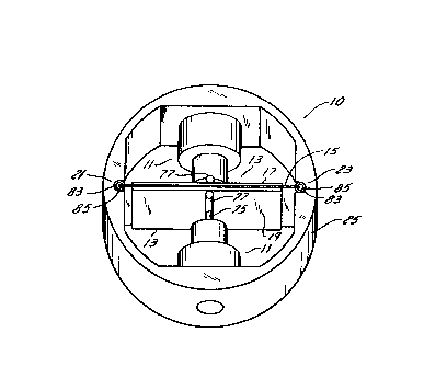
Referring first to FIGS. 1 and 2, the fluid pumping
apparatus 10 of the present invention is shown to include
pumping means 11 for supplying a fluid under pressure. An
energizer 13 is arranged in driving relationship to the
pumping means 11 and includes a generally planar flexure
member 15 having first and second piezoelectric laminates,
17, 15 respectively, supported thereon. The flexure

~270027
-- 5
member 15 includes a first edge 21 and a second edge 23, the
edges 21, 23 being resiliently constrained for substantially
preventing longitudinal movement thereof while yet permitting
lateral oscillating movement of the energizer 13 when an
electrical signal is applied. The pumping means 11 and the
energizer 13 may be supported by a frame 25 selected to be of
a size and shape for convenient integration with a pneumatic
cylinder. If such integration is unnecessary, a convenient
lo frame 25a may be configured as in FIG. 3. It is to be
appreciated that the energizers 13 depicted in FIGS. 1, 2, 8-
12 are portrayed in simplified form for easier understanding
and details of the preferred embodiments of the energizers 13
are shown and described following with reference to FIG. 4.
More particularly, the pumping means 11 is preferably
embodied as one or two pumps 27 of the reciprocating, check
valve type as shown and described in United States
Letters Patent No. 3,936,245.
For ease of manufacturing, it is preferred that the pumps 27
be positionable along their longitudinal axis, that axis
being normal to the longitudinal axis of the energizer 13.
As further described below, this will permit adjustment to a
position whereby the pumps 27 can provide their maximum
pressure capability. Adjustment may be accomplished by any
known, convenient means such as an adjusting screw (not
shown) or the like and this arrangement may be used,
irrespective of whether the pumping means 11 is embodied as
one or two pumps 27. Referring to FIG. 4, the pump 27 is
shown to include a stationary body 29, a movable pumping
piston 31 and a resilient inlet check valve 33 cooperating
with inlet passages 35 for filling the pump 27 with pneumatic
fluid during the suction stroke and for confining it during
the pumping stroke. A discharge check valve 37 and discharge
passages 39 permit the compressed, pumped fluid to be
I.E
:.
..
, . ..
.
.
~-

:12~30~7
expelled to the outlet 41 during the pumping stroke. The
piston 31 is slidably movable in the body 29 and supported
therein by a resilient diaphragm 43.
Referring next to FlG. 5, one preferred embodiment of
the energizer 13, sometimes termed a quadrimorph energizer
13a, is shown to include a flexure member 15 formed of a
thin, generally planar electrically conductive material
such as one ~uarter hard brass, titanium or steel and has
first and second generally planar surfaces, 49 and 51
respectively, a first end 53 and a second end 55. A first
piezoelectric laminate 57 is disposed on the first surface
44 while a second piezoelectric laminate 59 is supported
by the firs laminate 57. Similarly, a third laminate 61
is disposed upon the second surface 51 and a fourth
laminate 63 is supported by the third laminate 61. The
piezoelectric laminates 57, 59, 61, 63 of this embodiment
and those of other embodiments disclosed herein are
preferably formed of a lead zirconium titanate based
ceramic although other known piezoelectric materials such
as barium titanate may also be used, but perhaps with some
sacrifice in maximum deflection. As best seen in FIGS. 5
and 6, the flexure member 15 of the embodiments will have
a thickness "t" of 12-16 mils, a mil being one thousandth
of an inch. The laminates 57, 59, 61, 63 as well as those
of other embodiments will be of uniform thickness one to
the other and will have a preferred thickness in the range
of 6-8 mils. An exemplary energizer 13 will have a
flexure member 15 with a length Ll of approximately 3
inches, a width W of approximately 1.5 inches while the
length L2 of the laminates will be in the range of 2.5
inches to 2.75 inches and centered longitudinally on the
flexure member 15. The orientation of the polarized
laminates 57, 59, 61, 63 is preferably as shown in FIG. 5
where the dot is closely adjacént to and identifies those
.
.
~.
'~ . '' - .

~Z7C~
surfaces which are of positive polarity and which lie
parallel to the surface of the flexure member 15.
The piezoelectric laminates 57, 59, 61, 63 are
pre~erably selected in view of the stroke and displacement
of the pumps 27 which define the embodiment of the pumping
means ll and the maximum desired output pressure from the
apparatus lO.
In general, for a simply supported piezoelectric beam
where the laminates are energized in series, the free
displacement, under static conditions is in accordance
with the following equation
X = 3d3l L2 V (1 + t/T) /&T2
where t = the combined thickness of the flexure member 15
and epoxy. When t/T <<~1 , then the equation reduces to
X = 3d3l L2 V / 8T2
The blocked force Fb, is given by the product of the
free deflection, df, and the stiffness, K. In the
dynamic mode, the displacement is given by
X -~f,~ p ~ ![~ Z l 2~ rQ ~ 2 ) -~z
However at frequencies well below resonance or in the
static mode, f ~ O and Kp O and X = F/K or F = XK.
In the above formulas, X is the deflection in meters,
d31 is the piezoelectric coefficient for specific
materials, L, W and T are length, width and thickness
respectively in meters and V is the peak voltage in
volts. ~ is the ~uality Factor, ~ and fr are
respectively the frequency and the resonant frequency of
the system, and Kp is the stiffness associated with
pumping the fluid.
Affixation of the first laminate 57 and the third
laminate 61 to the flexure member 15 and of the second
laminate 59 and the fourth laminate 63 to the first

1270027
laminate 57 and third laminate 61, respectively, is
preferably by a low viscosity adhesive which will prevent
the laminates from shearing movement with respect to one
another. One such adhesive is LOCTITE no. 326 used with N
primer. An epoxy cement having a conductive metal such as
powdered nickel blended therewithin is also satisfactory.
A method for applying the adhesive is to spray the primer
on one surface, e.g., the first surface 49 of the flexure
member 15 and to apply the adhesive to the mating surface,
e.g., the negatively polarized surface of the first
laminate 57.
FIG. 7 illustrates what may be termed a b~unimorphic
energizer while FIG. 8 illustrates a bimorphic energizer,
the dimensions of a preferred embodiment of the
generally-depicted laminates 65 ànd flexure members 15 are
selected to maximize the length to thickness ratio for
optimum deflection. The simplified circuitry shown in
FIG~. 5, 7 and 8 are to illustrate the manner in which an
energizer 13 may be connected to an electrical drive
circuit for applying an electrical signal.
Because the laminates 65 used to construct the
energizer 13 are rather brittle and may develop a small
fracture when the energizer 13 is caused to oscillate,
thereby resulting in electrical discontinuity of the
electrode surface, it may be necessary to provide a
compliant conductive layer to preserve electrical
integrity of the laminate 65. Accordingly and referring
next to FIG. 10, it may be desirable to overlay the
outermost laminate 65a with a layer or jacket 67 formed of
conductive silicone rubber and arranged to contact
substantially the entirety of the outermost surface of
laminate 65a. It will thereby be electrically connected
to flexure member 15 while yet being isolated from the
surface electrode of laminate 65 by the non-conductive
epoxy lsyer 69. When passing lead wire 73 through the
* Trade Mark
: `~
; -,
''":"
' ' ' ' . '

~ ~70C~7
jacket 67, care is to be taken to electrically insulate
the wire 73 and the jacket 67 from one another. A s~all
recessed notch 71 may be formed at one corner of laminate
65a to permit the affixation of an electrical lead wire 73.
~eferring again to FIGS. 2, 5, 7, 8 and lO and
irrespective of whether a jacket 67 is employed, it will
be convenient to make electrical connections to the outer
surface electrodes of the laminates 5~ and 63, 65 or ~5a
and to the flexure member 15 by employing a pump stem 75
formed of a dielectric material and including a
cylindrically-shaped, dielectric crossbar segment 77, the
longitudinal axis of which is parallel to the surfaces 49,
51 and normal to the longitudinal axis of the flexure
member 15. The stem 75 and its crossbar segment 77
thereby define a generally T-shaped structure. P~eferring
to EIGS. 12 and 13, the segment 77 may have a slot 7~
formed therein along a portion of its length and sized to
receive a pair of resilient, electrically conductive
contacts 81 which are electrically coupled together and
which may be brought out through the stem 75 to receive an
electrode connection. When electrical connection to the
crystal, 65 generally, or jacket 67, as the case may be,
is formed in this way, the energizer 13 is thereby lightly
supportingly clamped snd in the case of parallel-connected
laminates as shown in FIG. 5, the connection also performs
the function of a more complex arrangement known as a
wrap-around electrode.
When tlle apparatus lO is constructed and arranged as
described above, it will be apparent that the pumping
means 11 will be caused to reciprocate and therefore
supply fluid under pressure by the oscillatory action of
the energizer 13. In order to cause the energizer 13 to
deform by bending or bowing, rather than by elongating, to
achieve this oscillatory action, it is preferred that the
edges 21, 23 or ends 53, 55 of the flexure member 15 be
~"
...,.: . .
'. - '' ,, :
,,
-
~: .

lZ70V~7
-- 10 --
supported in a manner to restrain elongation while yetpermitting bending. One way to achieve this result is
shown in FIGS. 1, 2, 3 and 14 wherein the side walls of
the frame 25 or 25a have formed therewithin a pair of
generally C-shaped notches or grooves 83 having a curved
portion sized to receive a cylindrically shaped
resilient, hollow support tube or sleeve 85. A
preferred support tube 85 useful with energizers 13
having the general dimensions described above may be
formed of silicon rubber of about 150 mils outer
diameter and a wall thickness of about 50 mils. A
straight, longitudinal cut 87 is made throughout the
length of the support tube 85 and an edge 21, 23 or end
53, 55 of the flexure member 15 inserted therewithin for
support. Placement is preferably in a manner such that
the edge 21 or end of the flexure member 15 is generally
coincident with the longitudinal center axis of the tube
85 and thereby avoids contact with that portion of the
tube wall opposite the cut 87. If a higher pumping
pressure capability is desired, a pair of energizers 11
may be arranged and supported in tandem as shown in FIG.
15 which illustrates the use of two bimorph type
energizers 11 as depicted in FIG. 8 and which are
electrically insulated one from the other by a
relatively thin layer of dielectric material 89 and
triple energizer stacks may also be feasible.
Because an enerizer 11 constructed as a bimorph as
generally depicted in FIG. 8 has, when oscillating at
its resonant frequency and therefore at large
amplitudes, a greater tendency to crack unless its
travel is limited, it has been found desirable to adjust
the position(s) of the pump(s) 27 to reduce the pump
clearance volume, thereby limiting the amplitude of
energizer oscillation. It is to be appreciated that
if the pumping means 11 embodies only a single pump
27, it is preferable to install a resilient

~270027
-11 -
snubber or spring (not shown~ on that side of the
energizer 1~ opposite the pump 27 employed and in order to
limit the oscillation amplitude of the energizer 13.
While ~ost HVAG pneumatic control systems operate in
the range of 0-20 p.s.i.g., it is believed that highly
satisfactory positioning control of pneumatic cylinders
may result from the use of pressures in the 0-10 p.s.i.g.
range. In that event, a bimorph energizer 13 as shown in
~IG. ~ has been found to be preferred for the application
and if a higher pressure capability is required, the
tandem bimorph of FIG. 15 is preferred.
Piezoelectric fluid pumping apparatus 10 constructed
in accordance with the above teachings are preferably
driven at their resonant ~requency for greatest a~plitude
of oscillation. In some applications, it may be desirable
to construct a cylinder into which apparatus 10 is
integrated to permit bleeding its internal pressure to
ambient level. In that event, a parallel bleed port and
actuating piezo or solenoid (not shown) may be coupled to
outlet 41.
While only a few preferred embodiments of the
inventive apparatus 10 have been shown and described, the
invention is not intended to be limited thereby but only
by the scope of the claims which follow.
~ .
'': -
.
,
. .

Dessin représentatif
Une figure unique qui représente un dessin illustrant l'invention.
États administratifs

2024-08-01 : Dans le cadre de la transition vers les Brevets de nouvelle génération (BNG), la base de données sur les brevets canadiens (BDBC) contient désormais un Historique d'événement plus détaillé, qui reproduit le Journal des événements de notre nouvelle solution interne.

Veuillez noter que les événements débutant par « Inactive : » se réfèrent à des événements qui ne sont plus utilisés dans notre nouvelle solution interne.

Pour une meilleure compréhension de l'état de la demande ou brevet qui figure sur cette page, la rubrique Mise en garde , et les descriptions de Brevet , Historique d'événement , Taxes périodiques et Historique des paiements devraient être consultées.

Historique d'événement

Description Date
Inactive : CIB de MCD 2006-03-11
Inactive : Demande ad hoc documentée 1994-06-05
Le délai pour l'annulation est expiré 1993-12-06
Lettre envoyée 1993-06-07
Accordé par délivrance 1990-06-05

Historique d'abandonnement

Il n'y a pas d'historique d'abandonnement

Titulaires au dossier

Les titulaires actuels et antérieures au dossier sont affichés en ordre alphabétique.

Titulaires actuels au dossier
JOHNSON SERVICE COMPANY
Titulaires antérieures au dossier
DAVID N., II ABUJUDOM
JOSEPH P. DOUGHERTY
KEVIN M. STENGEL
Les propriétaires antérieurs qui ne figurent pas dans la liste des « Propriétaires au dossier » apparaîtront dans d'autres documents au dossier.
Documents

Pour visionner les fichiers sélectionnés, entrer le code reCAPTCHA :


Pour visualiser une image, cliquer sur un lien dans la colonne description du document. Pour télécharger l'image (les images), cliquer l'une ou plusieurs cases à cocher dans la première colonne et ensuite cliquer sur le bouton "Télécharger sélection en format PDF (archive Zip)" ou le bouton "Télécharger sélection (en un fichier PDF fusionné)".

Liste des documents de brevet publiés et non publiés sur la BDBC .

Si vous avez des difficultés à accéder au contenu, veuillez communiquer avec le Centre de services à la clientèle au 1-866-997-1936, ou envoyer un courriel au Centre de service à la clientèle de l'OPIC.


Description du
Document 
Date
(aaaa-mm-jj) 
Nombre de pages   Taille de l'image (Ko) 
Revendications 1993-09-20 3 108
Abrégé 1993-09-20 1 15
Dessins 1993-09-20 4 67
Description 1993-09-20 12 422
Dessin représentatif 2001-07-04 1 9
Taxes 1992-03-22 1 27