Note : Les descriptions sont présentées dans la langue officielle dans laquelle elles ont été soumises.
2~32~
DIGITA~ COL~R DEMOD~ATOR
1 BACKGRO~ND OF THE IN~ENTION
Pie~d of the Invention
The present invention relates to digital signal
processing in a television receiver, and particul~rly
relates to the improvement of a color demodulation system.
Description of_the Prior Art
In conventional color demodulation systems, the
clock signal which is used for A/D conversion has a
quadruple subcarrier fre~uency (4FSc) phase locked to a
color burst s;gnal. Data of 4FSc in frequency are pha~e-
shifted to be re:Lated to each other as (R-Y), (B~Y), -(R-
Y ) and
-~B-Y). Every other piece of the data i8 extracted to
perform color demodulation.
In conventional color demodulation systems, color
demodula~ion can be perormed even if the system receives
an analog composite signal which is sent out from a video
, tape recorder, for example, and in which a color bur~t
gignal and a horizontal synchronizing ~ignal are not
synchronized with each otherO Howevery since the video
signal is subjected to A/D conversion through the use o~
~ t~"
,:' .` ~ . ' ~
,
~2~2
1 the clock signal of the quadruple subcarrier frequency
4Fsc~in the system, the number of the samples of one line
may not ~e 910. When signal processing is performed, such
as scanning line interpolation and double writing into a
S memory to double a scanning line, the number of the
samples of one line is not a fixed value locked to a
horizontal periocl but fluctuates. This engenders problems
such as manufacturing lH delay lines. Aiso, system
circuitry becomes complex.
SUMMARY OF THE I~VENTION
This in~ention solves many problems inherent in
prior art apparat:usO
This invention provides a digital color
demodulator havingi. a first phase locked loop circuit
which generates an analog subcarrier signal phase locked
to the color burst signal; a second phase locked loop
circuit which generates an internal system clock~signal
phase locked to a horizontal period; a Y/C color
~eparation ~ircuit operating under the internal system
20~ clock signal;. a pair of multiplying cir.cuits, one of
which multiplies a digital subcarrier signal, converted
from the analog aubcarrier signal, with the color signal,
and the other Qf whiich multiplies the digital subc~rrier
~ignal, phase delayed by substantially 90, with the color
~2~3~1
1 signal, thereby performiny orthogonal de~odulation of the
signal~
The digital processing circuits of th;s invention
are all dxiven by the internal system clock signal
generated by the second phase locked loop circuit~ E~or
that reason, signals can be digitally processed in the
circuits, since the number of samples per horizontal line
remain~ a fixed value locked to the horiz~ntal period,
even if an analog composite video signal does not have a
prescribed correlation between the subcarrier fre~uency
and frequency of horizontal synchronizing signal.
. . .
BRIEF DESCRIPTION OF T~E DRh~IM~S
FIG. 1 sllows a block diagram of a first embodiment
of the present invention.
FIG. 2 shows a block diagram of a Y/C separa~ion
circuit in the first em~odiment.
FIG. 3 shows a block diagram of a ~second
embodiment of the present invention.
FIG. 4 shows the constitu~ion and characteristic
of a band pass ~;lter in the second embodiment.
DETAILED DE CRIPTION OF THE PREFE~RED EMBOPIMENT
Two preferred embodiments of the present invention
are described belowO
......... _.. ~ . __ . _ _._. . __.
, . ~
3~L
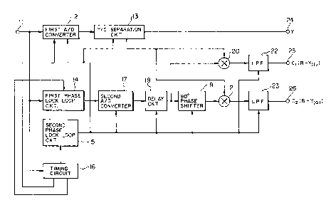
1 FIG. 1 shows a block diagram of a first embodiment
o the invention. An input terminal 11 provides an analog
composite video signal to a first A/D converter 12, a
first phase locked loop circuit 14, and a timing circuit
16.
The first AjD converter. 12 operates under an
internal system clock signal of 910FH (~ denotes a
fre~uency o~ horizontal sinchronizing frequency~. Clamp
pulses describecl below are supplied ~rom the timing , --
circuit 16 to the first A/D converter 12 so t.hat the
converter provides a digital composite video signal to a
Y/C separation ci.rcuit 130 -
The ~/C separation circuit 13 separates the
digi~al composite video signal from the first A/D
converter 12 into a luminance signal Y and a color signal
C modulated by a color subcarrier signal. The luminance
sîgnal Y is outputted to an output terminal 24. The color
signal C is outputted to a first and a second multiplier
2n and 21 described below~
The timing circuit l6 separates a horizontal and a
vertical synchronizing signal rom the analog composite
~ideo signal supplied through the ;.nput terminal 11, The
: timing circ.uit. 16 generates: H pulses, synchronized with
the horizontal synchronizing signal and having a
horizontal period; clamp pulses, which are generated
.:, '.,. ' . " `
,
3~
1 depending on the back porch of the horizontal
synchronizing signal; and burst gate pulses, which are
generated at the time for extracting a color burst signal
. included in the analog composit~ video signalO
Fig. 1 shows a second phase locked loop circuit 15
which generates the internal system cl~ck signal of 910F~
in frequency, phase-locked to the H pulses sent out from
t~e timing circuit 16.
The first phase locked loop circuit 14 operates
under both the analog composite video signal supplied
throuyh the input terminal.ll and the burst gate pulses
supplied from the timiny circuit 16, and outputs an analog
subcarrier signa:L.
A secon~l A/D converter 17 converts the analog
subcarr1er signa:l from the ~irst phase locked loop circuit
14 into a digit:al subcarrier signal, which is inputted
into a delay circuit 18 next to the second A/D converter.
The delay circuit 18 delays the digital subcarrier
signal by th~ equivalent o~ a delay in the Y/C separation
circuit 13 and outputs the delayed digital subcarrier
signal to a 9D phase shifter 19 and .to the first
multiplier 20 next to the delay circuit. The 90 phase
shifter 19 is a one-sample delay (one-sample delay denotes
a l~910FH delay).
:,
,, .
~7~3~
1 The first and the second multipliers 20 and 21 are
conv,entional digital multipliers and multiply the color
signal C ~modulated by a color subcarrier signal) by
abov'e-mentioned digital subcarrier signals. Both first
and second multipliers 20 and 21 outputs a demodulated
color signal including harm;onic components. The output
si~nals of the first and second multipliers 20 and 21 pass
throu~h a first and a second low pass filters 22 and 23,
respectively, so that color difference signals Cl and C2
are outputted to output terminals 25 and 26, respectively.
The first and second low pass Eilters 22 and 23 are
conventional d~gital 'filters which remove harmonic
componënts included in the output signals of the first and
the second multipliers 20 and 21, respectively. The
- signals Cl and C,2 correspond to R-Y(I) a-nd B-Y(Q) signals,
respectively.
The digital color demodulator will now be
described in detail. The analog composite video signal is
applied to the input terminal 11 with an exemplary
property of 75 ~- and 1 Vp-p. Tne first A~D converter 12
converts the analog composite video signal into the 8-bit
digital composite video signal. The irst A/D c~nverter
12 includes a low pass filter and a pedestal clamp
circuit~ which operates under the clamp pulses supplied
from the timing circuit 16. The first A/~ converter 12
~'
~7~?3~
1 performs sampling by internal system clock signal
generated by the second phase locked loop circuit lS and
having a freguency of 910F~.
The Y/C separation circuit 13, which is supplied
with the digital composite video sisnal from the firs~t A/D
converter 12, is made of a digital filterl or example,
shown in FIG.2. The Y/C separation circuit 13 separates
the luminance siynal Y and the color signal C modulated by
the color subcarrier signal, and outputs the luminance
signal and the color signal. FIG. 2 shows a terminal 131
to which the di!3ital composite video signal is supplied
fxom the first A/'D converter 12, a terminal 132 from which
thP luminance signal ~ is generated, and a te~minal 133
from which the color signal C modulated by the color
subcarrier signa~ is generated. FIG. 2 also shows delay
lines z-l for ~:l/9lOF~), and a positive and a negative
half weighting circuits 142 and 140. The delay lines Z-}
and the weighting circuits 140 and 142 are conventiona
ones.
The first phase locked loop circuit 14 operates
with both the analog composite yideo signal.supplied from
the input terminal 11 and the burst gate pulses supplied
f~om the timing circuit 16, so that the first phase locked
loop circuit outputs the analog subcarrier signal phase-
locked to the color burst signal~
. .,: ' , .
3~L
1 The second A/D converter 17 is supplied with the
analog subcarrier signal from the first phase locked loop
circuit 14 and outputs the 8-bit digital subcarrier
signal. The second A/D converter 17 includes a low pass
filter for removing harmonics i.ncluded in the analog
subcarrier signal, an amplifier for amplifying the signal
to the dynamic range o~ the second A/D converter, and a
bias circuit for biasing the signal to the center of the
dynamic range ~f the A/D converter. The second A/D
converter 17 samples the analog subcarrier signal by using
the internal system clock signal outputted by the second
phase locked loop circuit 15 and having the frequency of
' 910FH.
The delay circuit 18 delays the digital subcarrier
--signal to compensate for the delay caused by the signal
processing in the Y/C separation circuit 13. The digital
subcarrier signal generated by the delay circuit 18 and
the color signal C generated by the Y/C separation dircuit
13 are multiplied together by the first multiplier 20.
The digital subcarrier signal generated by the
delay circuit 18 is also supplied to the 90.phase shifter
19 which serves as a one-sample delay to delay the digital
subcarrier signal by substantially 90 and then supply the
signal to .the second multiplier 21.
. ~ . . -:
. . ,. .: ,
3~
l The color signal C separated by the Y/C separation
circuit 13 i~ supplied to the second multiplier 21 as well
as the firs.~ multiplier 20. ~ach of the first and the
second multipliers 20 and 21 is an 8-bit/8-bit multiplier
in the exemplary embodiment. The first and the sec~nd
multipliers per~orm orthogonal demodulation with the ~nce
delayed digital subcarrier signal from the delay circuit
18, the twice delayed digital subcarrier signal from the
~0 phase shifter l9, and the color signal C..
rrhe low pass filters 22 and 23, ~hich are
conventional digital filters, are connected to the output
sides of the fils and the second multipliers 20 and 21,
respectively, so that the harmonic components included in
the output signals Oe the multipliers and centerin~ about
a frequency of ~sc are removed from thP output signals to
thereby obtain the color difference~ signals Cl and C2.
Thus, the color difference signals Cl and C2 are outputted
to the output terminals 25 and 26.
The outputs from the irst and second multipliers
20 and ~1 can be changed from the color diference signals
R-Y and B-Y into signals I and Q by altering ~he
demodulation ax~s~ Such operation ob~lously, does not
depart from the character and ~spirit of the present
invention~
3~
1 The second phase locked loop circuit lS outputs
the internal system clock signal having the frequency of
910F~ and phase-locked to the H pulses generated by the
timing circuit 16. The internal system clock signal are
supplied as drive pulses to the circuits of the digital
color demodulator except to the first and the second
multipliers 20 and 21 and the irst phase locked loop
circuit 14.
FIG. 3 shows a block dia~ram of a second
embodiment of the present invention. In FIG. 3j like
parts and components are designated by the same reference
numerals as that in FIG. 1.
According to the second embodrment in FIG. 3/ the
band pass ~ilter 27 of linear phase and symmetric gain
-:characteristic i', connected as a digital filter to extract
the subcarrier. The set D~ bias level of the A/D
converter 17 is likely to fluctuate due to the temperature
characteristic thereof and a DC component comes into the
output 17a from the A/D converter due to the nonlinearity
thereof. Besides, a high-~requency noise inevitably c~mes
into the output 17a. The band pass filter is 50 provided
as to prevent the high-frequency noise from coming into
the output 17a.
FIG. 4(a~ shows the constitution of the band pass
filter 27 which is a transversal filter comprising our
~ ~" . :,
3~.~
~1
1 delay elements 71, 7~ 73 and 74 in series and adders 75
and 760 The clock signal of 910F~ in frequ ncy is used in
~ilter 27~
The adder 76 is a coefficient adder in which a
signal 75a is multiplied by -1/4, a signal 72a is
multiplied ~y ~1/2 and the s.ignals added to~ether. An
impulse response is (-0~25~0~0~5~0~-0~25)o
AS shown in FIG. ~(b), the band pass filter 27 has
the sy~netric gain characteristic having a peak at
substantially the subcarrier frequency FSc and acts to
remove the DC conlponent and the high-frequency noise.
The delay circuit lB connected to the band pass
filter 27 functi.ons so that the phase of the C signal
separated by the Y/C separation circuit 13 and that of an
input signal 18~ to the orthogonal demodulation section
120 are matched with each other.
According to the present inven~ion, a digital
color demodulation system operates with a clock signal
having a frequency of 910F~I phase-locked to ~ pulses even
if the analog composite video signal does not have a
prescribed correlation between the subcarrier frequency
and frequency of the horizontal synchronizing si~nal. For
that reason, the numb~r of the samples of one line is 910,
so that a correlation perpendlcular to picture data can be
taken~ ~ince a color difference signal is demodulated by
-, :,
....:
.. - ~ .
~Z7~32~iL
1 multiplying an A/D-converted digital subcarrier signal and
a color signal modulated by the subcarrier signal together
in the system, color demodulation can be performed even if
a sampling clock is not phase-locked to a color burst
signalO
Further, a DC component generated in an analog
section and an unexpected noise component are removed from
the system owing to the band pass filterO
The reliability of the digital color demodulator
is thus enhanced.
,
'
.~ ",~ , .. ......
, ~ ~ ' '.
:. . .: .
. ~
.. . .
:. ;, . ~ ,
, .