Note : Les descriptions sont présentées dans la langue officielle dans laquelle elles ont été soumises.
~'7~S~L6
TITLE
IMPROVED ELECTRIC FEl,CE WIRE CONSTR~CTION
BAC~;Jl~OUND OF T~IE INVENTION
Field of the Invention
This invention relates to an improved electric fence wire
construction for use by cattlemen, farmers, and others.
Electric fence wire constructions carry an electric charge
which shocks animals upon contact with the outer surface
of the construction and tends to prevent their crossing
the fence. These constructions are strung from fence
posts or other convenient attachment points. They may be
used as perimeter fencing to enclose animals or to keep
out predators. They may also be used to subdivide
pastures temporarily to insure that they are grazed
uniformly, in which case the electric fence wire
construction may be taken down and restrung every few days
forcing animals to graze different strips of land in
regular rotation.
1271:)S16
-- 2
The electric fence wire construction of this invention
comprises both support memDers and conductive members
which should have several inter-related, special
characteristics to perform well. The wire construction
should be abrasion resistant, sufficiently light in weight
to be portable, and flame resistant (that is to say,
self-extinguishing or unable to support combustion). It
should ~e reasonably flexible, yet strong, should knot
without breaking, and should hold a knot without
slipping. ~ecause these wire constructions may be
relocated several times, they should resist wear not only
while in use, but also duriny handling when they are taken
down and put up for relocation to another site. The
conductive members should have a high degree of
conductivity and be sufficiently malleable to perform
satisEactorily in spliciny. Furthermore, electric fence
wire constructions should retain these properties when
su~Jected to extremes oE weather and temperature over long
periods. For example, the wire construction should resist
fading, corrosion, and loss of strenyth in blizzards at
less than -50F (-46C) and direct sunlight at above 100F
(38C), and have a low coefficient of linear expansion to
resist contraction when cold and sagging when warm.
Descri~tion oE the Prior Art
For several years the prior art has been typified by
single component constructions of galvanized steel wire,
which are sufficiently thick to serve both conducting and
supporting functions simultaneously, and by a plied, rope-
like combination electric fellce wire construction in which
a~ olefin fiber such as polyethylene or polypropylene fiber
serves as the supporting member and stainless steel wire
serves as the conducting member. United States patent
~L~7~)5~6
3,291,897 (Bramley) shows an example of this latter
construction.
These prior art electric fence wire constructions suffer
several drawbacks, which as far as ~e know the art has not
solved in the sev~nteen years since the ~ramley ~atent
issued. The single component steel wire constructions,
while strong, are too heavy for easy ~ortability and
installation and hence are impractical in many situations.
In the conbirlations of olefin supporting members with
stainless steel, the stainless steel wire construction
when spliced or knotted has heated sufficiently to cause
fires. To compound this problem, flames have been carried
along the length of the wire construction by prior art
supporting members, spreading the fire to adjacent fields
or buildings. These prior art su~porting members have
also been subject to loss of strength upon exposure to
weather, particularly to the ultraviolet rays in
sunlight Furthermore, olefin fibers do not hold a knot
well; the ability to hold a knot is important, for
example, when splicing the beginning of one package of
electrlc fence wire to the end of another or when
repairing a break.
composite electric fence wire constructions of the prior
art have occasionally been made with tinned copper as the
conductor, which eliininated problems of low conductivity
but was too weak to withstand breakage during use, and
particularly during winding ancl unwinding the wire
construction during temporary installation. Hence, as far
as we know tinned copper is used little if at all.
We have noticed an additional problem in ~rior art
combination electric fence wire construction when made for
~ 7~5~L~
example from stainless steel supported by a conventional
olefirl. When stretcne~ during installation or use, the
conducting memo~r may brealc while the supporting member
remains intact. It is then difficult to locate the
particular section oi the electric fence wire construction
whicn needs replacing.
Summary of the Invention
Our invention can solve or mitigate these problems and
provides additional advantages. It makes possible the use
of low-stretch, light-weight support members, conductors
Witll suuerior conductivity, and provides electric fence
wire constructions with superior flame resistance,
superior strength, superior resistance to wear and
weatheriny, and superior knotting characteristics. In
particular, the use of low stretc~l supporting materials is
effective in preventing fracture of the conductor
sign1Licantly before breaking of the entire fence wire
construction.
In one as~ect the present invention comprises (a) an
elongated support member which comprises a core material
and a coating and (b) an elongated conductive member. The
core material of the support member provides a significant
a~nount of strength to the support member. By braiding or
twisting and plying we assemble the coated support member
and the conductive member with a substantial portion of
the conductive member exposed to the outer surface of the
construction. One or a number of supporting filaments or
strands may be assembled with one or a number of filaments
or strands oE conductor to make the electric fence wire
construction. We use "filament" to identify a single
fiber; groups of filaments make up a "strandn; and one or
more strands make up a "yarn".
~27~)5~6
A single coating may be applied around each strand of
supportin~3 material. Alternatively, strands may be coated
or impregnated with a material of low viscosity such that
each individual filarnent as well as the entire yroup is
encapsulated, for example using a reslnous solution or
latex.
By selecting a coating material which is characteri~ed by
substantially greater abrasion resistance, or fracture
resistance when knotted, than the core material, we have
found that high-strength, low stretch core materials such
as fiberylass, which would be expected to break when used
in electric fence wire constructions, can in fact be
adapted for such use and the cost of such coatings is more
than offset by the resulting combination of strength,
durability, flexibility and other improved properties
which are obtained. For example, the application of such
coatinys yives abrasion resistance to each oE the
individual ~ilaments and results in improved properties
ir,so$ar as resistance to breakage due to knottinc~ is
concerned.
In addition, by selecting and applying a coating material
which is resistant to weathering (for example, exposure to
chemicals, rnoisture, and the effects of ultra-violet
radiation), to a substantially greater degree than the
core material, one is able to use core materials which
would not otherwise be satisfactory in electric fence wire
constructions. Moreover, not only are the properties
obtained by using a coating material and a core material
in the support member improved over the use of either
material alone, but the improvements are sufficiently
great to justify the added step of applying the materials.
516
-- 6
The coating may be applied using any one of various
methods, including e~trusion and crosshead extrusion, or
it may be applied as a liquid using polyvinyl chloride in
the form of a plastisol, organosol, latex or other
solution or dispersion, by dip-coating, curtain coating,
or other method, metering off any excess if necessary, and
then drying, fusiny or curing, depending upon the
re~uirements of the solution or dispersion. The resulting
coated strand preferably has a total diameter of about 20
r,lils (50~ microns).
~ther possi~le coatings include plastics or rubDers such
as polyurethanes, acrylics and polyesters chosen for their
good weather resistar,ce, flame retar~ance, ability to
receive color and color fastness, ability to impart good
knot holdiny characteristics (l.e., not slippery), or
abrasion or fracture resistance. These coatings may be
solid or plastic foams.
We prefer to combine filaments of a support material into
strands and apply coating to the strands. We then prefer
to ply one or several of these strands with strands or
individual filaments of conductive material into yarns
containiny support material and conductive material, and
to ply these yarns to make the final electric fence wire
constructiorl. Braiding may also be used to make these
constructions and has the advantage of unraveling less
than plied constructions.
The support me~ er we prefer to use is fiberglass coated
with a polyvinyl chloride which includes flar.le inhibitors
of the kind known for use with polyvinyl chloride. ~le
have found this composite is flame resistant, strong,
low-stretch, and capable of holding a knot well. It also
has reduced problems of abrasion and loss of strength in
o~6
knotting due to stress fracture, which fiberglass alone
would exhibit. ~uch composites have be~n proven in
outdoor use as insect screens to have superior
c~aracterl~tics or resistance to weathering an~ fading,
but ue are aware of no previous use in electric fence wir~
construction or under the full range of conàitions to
which electric ~ence wire constructions are su~ject.
The conductive me~nber we pref~r to use is aluminum wire,
and we find most preferable wire drawn from an alloy which
has on its surface a metallurgically bon~ed aluminum alloy
coating that is anodic to the core and thus
electrolytcally protects the core against corrosion, such
as known at present in the industry as Alclad 5056 (Trademark).
Alclad 5056 has provel its corrosion resistance through
use in Draided cable armor wire, insect screen cloth, and
chain llnK fence, but we are aware of no previous use in
electric f~nce wire construction or under the full range
of con~itions to wilich electric fenc~ wire constructions
are subject.
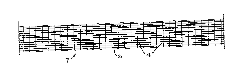
~rief Description ~f The Drawings
Figure 1 is a side elevational view of a twiste~ and plied
electric fence wire construction;
Figure 2 is a cross-sectional view taken at line 2-2 of
Figure l;
Figure 3 is an enlarged cross-sectional view of one stran~
of a support mem~er of Figure l;
~7~35~6
Figure 4 is a side elevational view of a braided electric
fence wire construction;
Figure 5 is the top elevational view of one embodiment of
a ri~bon electric fence ~ire construction according to the
present invention;
Figure 6 i5 a tnree-quarter viewfof the embodiment of
Fiyure 5.
Figure 7 is a cross-sectional view taken at line 7-7 of
Figure ~. These figures are not drawn to scale.
etdlled Descri~t on_of the Preferred bodir,lents
Reterring to the Figures 1 to 3, an electric fence wire
construction 1 comprises yarns 2 which are plied
together. Eacn yarn 2 is made up o~ coated sul~port
members 3 and conductive members 4 which are twisted
togetner. The sùpport members comprise filaments S, which
may be fiberglass, and a coating 6, which may be polyvinyl
chloride. In Fiyure 4, the coate~ support members 3 and
the conductive members 4 are braided together. Figures 5
to 7 show~ one embodir,lent of a ribborl electric fence wire
construction. :The ribbon 7 is made up of coated support
members 3 and conductive members 4 which are woven in a
conventional ribbon construction.
We pre~-er to ply two strands of fiberglass supporting
material coated with polyvinyl chloride and two filaments
of aluminum conductor together at about 3 1/2 turns per
inch ("TPI~) in the nZ~ direction, and to ply three of
these yarns together at 1 1/2 TPI "S" twist to provide the
~271~S~6
finished product, which is therefore composed of six
strands of a coated fiberglass and six filaments of
aluminum conductor. The individual yarns in our invention
may preferably be twisted from about one to about si~
turns per inch and the final yarns plied in a yarn from
a~out one-half to six turns per inch. The electric fence
wire construction of the present invention may be braided
or twisted and plied on conventional machines such as
those used for twine or rope.
In ribbon embodil,lents we prefer to use support members
comyrising a fiberglass core coated with polyvinyl
chloride, althou~h other suyport mem~er constructions may
be used. We also prefer to use in ribbon embodimellts a
con~uctive member of aluminuln, most preferably haviny a
core of alu.~inum and a cladding of aluminurn alloy such as
Alclad 5~56. The conductive member may be woven,
including forms of interlacing, (i) lengthwise along the
ribbon (that is, in the warp direction), (ii) across the
ribbon, or (iii) in both directions. The conductive
filaments may com~rise from zero to all of the filaments
or stands in either the lengthwise or crosswise
direction. Figures 5 to 7 shown an embodiment in which
about one conductive filament is used for every five to
ten of other suyporting lengthwise strands.
We prefer to use low-twist fiberglass strands known in the
illdUStry dS 37 1/~. The designation 37 indicates that
3700 yards of the fiberglass weigh one pound. The 1/0
indicates that tne number of twisted strands plied
together is one and the number of single strands twisted
in continuous filaments is zero. The individual filaments
making up a single strand of 37 1/0 may number between 800
and 1600 and may be either G (9 micrometers diameter) or
~ ~7~S~
-- 10 --
DE (6 micrometers diamete~). The tiberglass we use is
ty~ically continuous filamer3t made from electrical gr~de
glass~ Fiberglass weights may range from about 18 1/3 (or
15~0 tex) to about 150 1/0 (or 33 tex), where tex
indicates the number of grams per thousand meters of the
particular fiber.
Most fiberglass fioers in uncoated condition come wlth
chemical sizes (surface finishes containing some chemical
constituents other than water) applied by the
manufacturer. These may be starch sizes or preferably
lubricating hydrophobic sizes which keep water from the
glass and lubricate the individual filaments to reduce
aDrasion.
Glass is also desira~le for its low coefficietlt of linear
expansion, for example, typicalLy about 5 x 10 6
centilneters per centimeter per degree centigracle. ~y way
of comparison, steel has a factor of about 10 x 10 6,
aluminum a factor of about 20 x 10 6, and polypropylene
about ~0 x 10 6 centimeters per centimeter per degree
centigrade.
Our most preferred support members llave very low stretch,
less than about four to five percent elongation of single
filaments before breaking. Materials for such members
include fiberglass. ~igh modulus, high tenacity poly
(p-phenylene terephthalarnide) fiber such as Kevlar-type (trademark)
aramid fibers, and high tenacity rayon fibers may also be
used. ~upportiny materials with up to about ten percent
elongation of single filaments at break are also
desirable, and sup~ortiny materials of up to about thirty
percent elongation of single filaments at break may be
used. ~u~port Menlber core fibers rnay include polyester,
~L~7(~5~L6
nylon, and other materials, particularly ~here their
stretch properties are kept below thirty percent.
While materials such as the present Alclad 5056 (trademark) aluminum
is the most preferre~ conducting mem~er, other alurninum
alloys are ~referred and other conductors may be used
islcluding stainless steel and tinned copper. Aluminurn
used in our invention is preferra~ly about 0.010 inches
(U.0254 cln.) in diallleter but may ranye in diameter from
about .005 inches (0.0127 cln.) to about .020 inches
(0.050~ cm.).
The construction of this invention nas superior properties
in that it resists weathering and has superior
conductivity. ~y way of comparison, electric fence wire
constructlon in the urior art using uncoated olefins lost
its strength after two years oE outdoor use, whereas Eence
wire construction of the present invention should not.
Electric fence wire construction of this invention is
resistant to stretching, and particularly the supportiny
fibers are resistant to stretching, so that the conductor
and the supporting fibers in our tests break at
substantially the same time, which makes broken conductors
easy to locate. The wire construction of this invention
has also been found in our testiny to knot well, and to
resist stress fracture, abrasion, and flames. The
conductor is sufficiently malleable to ~erforr~l well in
splicing.
In the prior art, stainless steel wire construction was
typically plied as four strands polyethylene to one strand
of stainless steel wire construction to Inake up a yarn.
Three of these yarns were then plied together to make the
final electric fence wire construction, which therefore
contained a total of three ends of stainless steel
7~
conductor and twelve ends of supporting fiber of
polyethylene or polypropylelle. In some of this prior art,
the stainless steel wire construction had been over-fed to
make it lie loosely in the polyetnylene supporting fibers.
Preferred embodiments of the present invention have been
described above in detail for purposes of illustration.
Modifications may be made by those skilled in the art to
the preferred embodiment of electric fence wire
constructions described above in order to adapt them to
particular applications.