Sélection de la langue

Search

Sommaire du brevet 1271001 

Énoncé de désistement de responsabilité concernant l'information provenant de tiers

Une partie des informations de ce site Web a été fournie par des sources externes. Le gouvernement du Canada n'assume aucune responsabilité concernant la précision, l'actualité ou la fiabilité des informations fournies par les sources externes. Les utilisateurs qui désirent employer cette information devraient consulter directement la source des informations. Le contenu fourni par les sources externes n'est pas assujetti aux exigences sur les langues officielles, la protection des renseignements personnels et l'accessibilité.

Disponibilité de l'Abrégé et des Revendications

L'apparition de différences dans le texte et l'image des Revendications et de l'Abrégé dépend du moment auquel le document est publié. Les textes des Revendications et de l'Abrégé sont affichés :

  • lorsque la demande peut être examinée par le public;
  • lorsque le brevet est émis (délivrance).
(12) Brevet: (11) CA 1271001
(21) Numéro de la demande: 1271001
(54) Titre français: MECANISME D'AGRAFEUSE
(54) Titre anglais: STAPLER MECHANISM
Statut: Périmé et au-delà du délai pour l’annulation
Données bibliographiques
(51) Classification internationale des brevets (CIB):
  • B25C 5/16 (2006.01)
  • B25C 5/02 (2006.01)
(72) Inventeurs :
  • OLESEN, PAUL (Etats-Unis d'Amérique)
(73) Titulaires :
  • ACCO USA, INC.
  • SWINGLINE INC.
(71) Demandeurs :
  • ACCO USA, INC. (Etats-Unis d'Amérique)
  • SWINGLINE INC. (Etats-Unis d'Amérique)
(74) Agent: OSLER, HOSKIN & HARCOURT LLP
(74) Co-agent:
(45) Délivré: 1990-07-03
(22) Date de dépôt: 1986-09-15
Licence disponible: S.O.
Cédé au domaine public: S.O.
(25) Langue des documents déposés: Anglais

Traité de coopération en matière de brevets (PCT): Non

(30) Données de priorité de la demande:
Numéro de la demande Pays / territoire Date
799,080 (Etats-Unis d'Amérique) 1985-11-18
860,730 (Etats-Unis d'Amérique) 1986-05-07

Abrégés

Abrégé anglais


Abstract
A stapler having a magazine and a cover pivotal to open
positions to expose the magazine for loading staples. The pivotal
cover is urged to the closed position by a spring. The magazine
and cover have flat surfaces which abut when the cover is in its
fully open position to hold such position despite urging of the
spring.

Revendications

Note : Les revendications sont présentées dans la langue officielle dans laquelle elles ont été soumises.


-5-
The embodiments of the invention in which an
exclusive property or privilege is claimed are defined
as follows:
1. A stapler having a magazine and cover frame pivotal
about spaced-apart base pivot sections comprising
a magazine slide mounted for reciprocal
movement in the magazine;
an elongated spring with one end
connected to the magazine slide having
end walls and the other end connected to
the cover frame;
magazine slide having end walls and the
cover frame base pivot sections having
flat surfaces
such that upon pivoting the cover frame from its closed
position to its open position the spring will urge magazine
slide end walls into abutting relationship with the flat
surfaces of the cover frame pivot sections to hold the cover
frame in its open position.
2. The stapler of claim 1 in which the cover frame
includes a spring metal drive element having a base drive
element mounted on the cover frame and a flexible arm element
wherein the base drive element has sections which engage the
base pivot sections as the arm element is flexed.
3. The stapler of claim 1 which stapler includes a
spring metal drive element connected to the cover frame and
includes a cover having forward connecting lip means for
connection to the spring metal drive element and rear
deformable connecting ledge means connectable to the cover

-6-
frame whereby the cover is readily assembled with the spring
drive element and cover frame.

Description

Note : Les descriptions sont présentées dans la langue officielle dans laquelle elles ont été soumises.

282-127
~X~O~
STAPLER MECHANISM
Background of the Inventlon
Small desk type staplers have been available for many
years (U.S. Patent No. 2,702,384). A variety of techniques
have been proposed for retracting the staple stick pusher
during preloading o~ the stapler with the cover portion
pivotally swung to an open-position (U.S. Patent Nos.
308,367, 2,551,838, 2,603,781, and 4,187,971).
Summary of the Invention
BriePly, the present invention comprises a maga~ine with
a magazine slid~ and base having base pivot sections about
which a cover frame is pivotal. A spring has one end
connected to the slide an~ the other end to the ^~over frame.
The slide has end walls and cover frame side pivot sections
havP surfaces such that ~s the cover is pivoted open, a slide
end wall and a frame side pivot se~tion surface engage under
spring urging to hold the cover in the open position.
It is a feature tha~ the c~ver frame carries a flexible
spring element having a ~ase connected to the frame and
engagea~le with the base pivot sections. The flexible spring
element also carries the ætapler driver.
It is a further feature that the stapler has a snap-on
cover.
Brief Descrî~tion of the Drawings
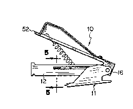
Fig. 1 is a side elevational view o~ the stapler
partially opened with a portion of the base removed;
`~

--2--
Fig. 2 is a side elevational view, partially sectioned,
showing the.staple partially opened with the base removed;
Fig. 3 is a sid~ elevational view, partially sectioned,
showing the stapler fully opened with the base removed;
Fig. 4 is a plan view ~f the stapler fully opened with
the base removed:
Fig. 5 is a sectional view taken along line 5-5 of Fig.
Fig. 6 is a plan vie~ of the stapler closed;
Fig. 7 i~ a side elevational view of the stapler;
Fig. 8 is a sectional view taken along line 8-8 of Fig.
7;
Fig. 9 is a front view of the stapler in the Fig. 7 open
position;
Fig. 10 is a front view of the stapler closed but in the
inoperative position;
Fig. 11 is a front view of the stapler ~n the driving
position;
Fig. 12 is a rear view of the stapler in the Fig. 7
position;
Fig. 13 is a sectional side elevational view of the
stapler cover disassembled;
Fig. 14 is a sectional side elevational view showing the
spring-frame partially a~sembled with the cover;
Fig. 15 is a sectional side elevational view showing the
spring-frame fully assembled with the cover, and
Fig. 16 is a bottom plan view of the cover.
De~cription of the Preferred Embodiment
In Figs. 1-8, stapler 10 includes base 11 (Figs. 1, 6
and 7) having magazine 12 and cover frame 13 pivotally
mounted about pin 14 which is journaled in upstanding
spaced-apart base ear sections 16 and 17. Base 11 includes
base ear sections 16, 17, ear support portions 19~ 20 and

7~
--3--
anvil portion 18. Cover frame 13 carries cover 63 as further
described (Figs. 13-16~.
Magazine 12 includes staple stick support bottom 21,
sides 22, 23 and upstanding notch-forming front pieces 24,
26. Sides 22, 23 have longitudinal slots 25, 27
respectively, to receive *etents 28, 29 positioned on the
inside of the ears 1~, 17. Housed in magazine 12 is stapl~
stick pusher 31 which is ~rged forward or rearward by cover
spring 32. Pusher 31 ~ncludes sides 34, 35, end piece 36,
slot engaging slide projections 37, 38 (see Fig. 5) and
spring hook 39 (see Fig. 4)0 Pusher 31 includes slit
openings 34b and 35b.
Cover frame 13 ha~ driver spring 15 connected to it by
rivet 40. Driver spring 125 includes horizontal base portion
41 with slot openings 42, 43 forming spring finger pieces 44,
46 which rest on ear support portion 19, 20. Spring 15 also
includes arm portion 47 and staple driver bl~e 48. Blade 48
has a rectangular opening 51 through which cover extension 52
extends. Extension 52 guides blade 48 as it is pushed down
to drive a staple and thereafter move~ up under spriny
action. All portions of spring 15 are preferably integrally
formed of spring steel. Cover ~rame 13 has opening 49 to
~ccommodate the spring. Cover 13 also i~cludes side pivot
sections 53, 54 which carry circular journal openings 55, 56
for rotation about pin 14. Sections 53, 54 have ~lat bearing
~5 surfaces 58, 59 respectively.
Turning to Figs. 1-4, it is seen that as cover 13 is
opened magazine pusher spring 32 urges the staple pusher 31
rearwardly until pusher flat end walls 34a, 35a engage flat
surfaces 58, 59 of cover side pivot sections 53, 54 under
spring tension to hold cover 13 in the open position (Figs~ 3
and 4). The force of spring 32 is su~ficient to hold pusher
end walls 34a, 35a against cover frame surfaces 58, 59 to
cause co~er frame 13 to remain in the open position without

7~L0~3~
--4--
the operator holding it in such position. This feature
facilitates loading staple sticks.
With respect to Figs. 5-8, magazine longitudinal
openings 2~, 27 carry pusher slide projections 37, 38 and
detents 23, 29 respectively. Spring 15 includes crown
portion 15a with cutout portions 30a, 30b creating narrow
front edges 15b, l5o (Fig. 6~. Also shown is spring crown
opening 15d.
In Fig. 10, cover frame 13 is positioned in magazine 12
with blisters 60, 61 providing a forced ~i~ between frame 13
and magazine 12.
Turning finally to Figs. 13-16, cover 63, preferably
made of moldable plastic material, includes cover top portion
64, side walls 66a, ~6b including side wall skirt sections
- 15 66c, 66d (see, in particular, Figs. 13 and 16). Cover 63
also includes forward connecting lips 67a, 67b, rear
deformable connecting ledge 68 and locating ~tton 69 for
ready engagement and assembly of ~pring 15, cover frame 13,
and cover 63.
Forward connecting lips 67a, 67b receive the front edges
15b, 15c of spring 15 (see Fiqs. 6, 14 and 15). As spring
front edges 15b, 15c are urged under lips 67a, 67b, locating
button 69 enters sprihg hole 15d to locate spring 15 and to
prevent its rearwaxd movement re}ative to cover 63 (Fig. 14).
Next, cover frame 13 is pressed toward cover top 64 causing
rear connecting ledge 63 to deform until frame 13 snaps into
the fully engaged posltion shown in Fig. 15~ ~lso shown are
side pivot section 53, rivet 70, cover extension 52 and cover
ribbing 71.
It is thus seen that cover 63 can ~e readily assembled
by nsnappingn it on staple 10 without the use of tools.

Dessin représentatif
Une figure unique qui représente un dessin illustrant l'invention.
États administratifs

2024-08-01 : Dans le cadre de la transition vers les Brevets de nouvelle génération (BNG), la base de données sur les brevets canadiens (BDBC) contient désormais un Historique d'événement plus détaillé, qui reproduit le Journal des événements de notre nouvelle solution interne.

Veuillez noter que les événements débutant par « Inactive : » se réfèrent à des événements qui ne sont plus utilisés dans notre nouvelle solution interne.

Pour une meilleure compréhension de l'état de la demande ou brevet qui figure sur cette page, la rubrique Mise en garde , et les descriptions de Brevet , Historique d'événement , Taxes périodiques et Historique des paiements devraient être consultées.

Historique d'événement

Description Date
Inactive : CIB de MCD 2006-03-11
Inactive : Demande ad hoc documentée 1994-07-03
Le délai pour l'annulation est expiré 1994-01-04
Lettre envoyée 1993-07-05
Accordé par délivrance 1990-07-03

Historique d'abandonnement

Il n'y a pas d'historique d'abandonnement

Titulaires au dossier

Les titulaires actuels et antérieures au dossier sont affichés en ordre alphabétique.

Titulaires actuels au dossier
ACCO USA, INC.
SWINGLINE INC.
Titulaires antérieures au dossier
PAUL OLESEN
Les propriétaires antérieurs qui ne figurent pas dans la liste des « Propriétaires au dossier » apparaîtront dans d'autres documents au dossier.
Documents

Pour visionner les fichiers sélectionnés, entrer le code reCAPTCHA :


Pour visualiser une image, cliquer sur un lien dans la colonne description du document. Pour télécharger l'image (les images), cliquer l'une ou plusieurs cases à cocher dans la première colonne et ensuite cliquer sur le bouton "Télécharger sélection en format PDF (archive Zip)" ou le bouton "Télécharger sélection (en un fichier PDF fusionné)".

Liste des documents de brevet publiés et non publiés sur la BDBC .

Si vous avez des difficultés à accéder au contenu, veuillez communiquer avec le Centre de services à la clientèle au 1-866-997-1936, ou envoyer un courriel au Centre de service à la clientèle de l'OPIC.


Description du
Document 
Date
(aaaa-mm-jj) 
Nombre de pages   Taille de l'image (Ko) 
Dessins 1993-10-07 5 114
Page couverture 1993-10-07 1 14
Revendications 1993-10-07 2 39
Abrégé 1993-10-07 1 10
Description 1993-10-07 4 156
Dessin représentatif 2001-04-30 1 6