Note : Les descriptions sont présentées dans la langue officielle dans laquelle elles ont été soumises.
~L~7~L46
This inv~ntion relates generally to tamper eviden-t end
closures for containers, and more par-ticularly, to an end
closure for a container for re-taining a comestible product.
Containers of the type with which the present invention is
concerned include end closures which maintain the container in a
saaled condition after packaging and provide a non-resealable
top to indicate tampering with the container if -the end closure
is moved.
One type of previously available tamper evident container
included a rotatable cap portion formed with a kni*e and a
weakened annular portion in the end of the container. The knife
requires separate manual engagement with a weakened groove in
; the end of the container. The cap is then rotated, causing the
knife to completely sever the weakened portion of the end por-
tion, opening the container. This ~onventional arrangement
results in a cap which is easily detachable from the container
and thus inconvenient to use. Furthermore, means are not pro-
vided for maintaining alignment of the knife blade with the
weakened annular portion during movement of the knife to sever
; 20 said portion. This type of construction is disclosed in U.S.
Patent No. 378,349.
It also is known to provide a sealed container with a thin
member or weakened membrane functioning as the seal. A helical-
ly threaded nozzle portion having a plurality of depending
knives is threaded about the outer lip of the container, so that
the blades are gradually brought into contact with the thin mem-
-2-
'~ ~ -, . ~ ' ' ,
'~ " -' - . ' -
~, .
: .
4~
ber. As tha nozzle is -threaded about the throat of -the con-
~ tainer, the blades gradually pierce the membrane and open the
- container. This structure does not provide a hinged cap when
the cutting operation is complet~, but merely secures the nozzle
to the container and insures communication of the contents
therein with the end of the nozzle. Furthermore, once the
nozzle is removed, it may be easily displaced from the con-
tainer. Such a container is shown generally in U.S. Patent No.
3,402,855.
U~S. Patent No. 4,125,203 discloses a twist top for use
with pull tab type beverage containers wherein the outer rotat-
able lid is attached to one end of the tab so that rotation of
the lid pulls -the tab away from the ~perture of the container
and also alig~s an aperture in the lid with the aperture of the
container to allow access to the beverage contained therein.
This patent does not disclose the use of a rotatable outer cap
with an intergral knife blade to sever an annular band in the
body portion of a container and provide a hinged lid for the
container.
U~S. Patent No. 4,5~7,995 in tha name of the same inventor
as the inventor herein discloses an end closure for a container
ha~ing a closed end with a cover rotatable thereabout. The
closed end has a raised portion which is engaged by a knife
blade integral with the cover. As the cover is rotated, the
blade severs the raised portion, revealing an aperture providing
-3_
' ', '' , . . :
~' ' '
~L~t~
access into th0 container. In this device, the closed end is
not complately opened, nor is it hinged.
U.S. Paten-t No. 4,598,837 also issued to the same inventor
as the in~entor herein discloses a tamper evident element in a
- container wherein rotation of an outer rotatable element causes
an integr~l knife blade to sever and detach said element from
the container, thus evidencing tampering when tha cover is
moved. This t~pe of container is suitable for retaining food
products ~n which small amounts are used at a time, but is not
suitable for retaining food products such as frozen juices
which, when the container is opened, are intended to be totally
discharged from the container promptly or after a short storage
period only.
We have found that the above disadvantages may be overcome
by providing a closure for a container wherein the closure is
¦ comprised of a closed endcap portion and an outer overcap por-
tion which fits over the closed end of the container and is
rotatably attached thereto. The overcap includes a knife edge
~; formed integrally with the inner circumferential surface of a
depending flange or ring thereof and built into the inside sur-
face of the cap which to engage a weakened annular band around
the wall of the container positioned proximate the endcap.
Prior to opening the container, the knife blade is located
within a well which is an integral part of the endcap. As the
overcap is rotated, the knife blade traverses an arc bsginning
at one end of the well, engages and severs the weakened annular
,
-4-
:
.
, ,, - . .
~. ' '' ~ ', ' ~
band and terminates at the other end of the well. The well is
further provided with a hinged portion so that when the knife has
traversed the arc around the container and has severed the endcap
from the body of the container lid~ the closure remains hinged to
the container. The hinge prevents the closure from being
completely detached from the container, and yet enables the
severed closure to be moved away from the open end of the
container whereby the contents may be rapidly discharged. If
desired, the closure can be detached from the container by tearing
the hinge. Furthermorel the closure may only be opened one time
and may not be resealed, thus rendering evident any tampering of
the container.
We have also found that the closure of the invention may
be provided with an alignment channel in the endcap to guide and
support the overcap during rotation thereof and maintain alignment
and engagement of the knife blade with the weakened annular band
as the blade is moved around the band.
From another aspect, the present invention provides a
tamper evident end closure for a container comprising: a
stationary endcap portion integrally joined to and forming a
closed end of said container by means of a weakened annular band
and an integral well having first and second ends and a hinged
portion, said well being located on said endcap portion and in
said annular band; an overcap portion attached to and covering
said endcap portion and being coaxially rotatable thereabout; and
a knife blade secured to said overcap portion and arranged to
engage and circumscribe said annular band as said overcap portion
-5-
. ~
',
.
~7~ 6
is rotated about said endcap portion, severing said endcap from
said Eirst end of said well to said second end of said well,
forming a hinged lid for said container.
The preferred embodiment of this invention will now be
described by way of example, with reference to the drawings
accompanying this speciEication in which:
FIG. 1 is a perspective view o-E a container incorporating
the end closure of the invention;
FIG. 2 is a sectional view taken along the line 2-2 of
Fig. 1 in the direction indicated generally;
FIG. 3 i5 a fragmentary exploded perspective view of the
knife and well portion of the end closure shown in Fig. 2;
-5a-
'
~ - ' ' .
~L~t7~ 6
FIG. 4 is a top plan view of the knife and well portion
thereof;
FIG. 5 is a sectional view taken along the line 5-5 of Fig.
4 in the direction indicated generally; and
FIG. 6 is a fragmentary elevational view, in partial sec-
tion, of the end closure portion of a container illustrating an
alternate embodiment of the invention.
Referring -to Figure 1, a container 10 is depicted having a
body 12 including a wall 14. In the preferred embodiment, the
body 12 is generally cylindrical in configuration, although any
shape suitable for storing a desired product may be used. The
container 10 i~ further provided with a bottom 16 at one end,
constructed and arranged to be secured to the body 12 once the
container 10 has been filled with product. The bottom 16 may be
plastic or aluminum, and once installed, the contents of th~
container are hermetically sealed therein to preserve product
life. Body 12 is provided, at the end opposite bottom 16, with
the end closure 18 of the invention.
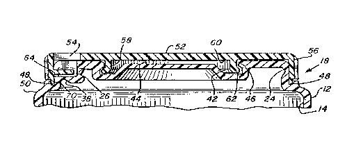
The end closure 18 is shown in greater detail in Figures 2
and 3, and is generally comprised of two main portions, these
being a stationary endcap portion 2C and an overcap portion 22.
i~ The endcap 20 is integrally joined to the wall 14 of the body 12
by an annular weakened band 24. Although the endcap 20, the
band 24 and the wall 14 of the invention are molded as one piece
from polymeric plast~c resins, any equivalent material may be
used which provides a sealed end for container body 12.
--6--
,
- ~ ' ', -
' ' ', :' ' ,' :
~ ' ' ' ' ' ~ . -
:
~ ~'7~
Also molded into the endcap 20 is a U-shaped wall 26 lo-
cated in the band 24. The purpose of the well 26 will be de-
scribed in detail below, it is structurally comprised of a floor
: 28, a vertical back wall 30, partially open first and second
side walls 32~ 34 (seen in Fig. 4), and an underside 36 with a
weakened hinge portion 38.
The endcap 20 is further provided with a face 40 into which
is molded an annular recess 42 defining a boss 44 and having an
annular 1ange 46. An open annular ohannel 48 suxrounds the
endcap 20 and is formed integral with a shoulder 50 of the body
12.
~: Figures 2 and 3 also illustrate overcap 22, provided with a
generally horizontally oriented flat lid 52, an access aperture
54, a vertically depending annular side wall or ring 56, and an
annular projection 58 which depends from the underside 60 of the
overcap 22. The annular pro~ection 58 is provided with a gener-
ally outwardly facing flange 62, spaced inwardly from the under-
side 60.
In order to rotatably secure the overcap 22 to the endcap
20, the flange 62 of the overcap 22 is of a configuration which
is generally complementary with the recessed flange 46 of the
endcap 20. The internal diameter of the flange 46 is greater
than the external diameter of the flange 62. Since the overcap
22 and the endcap 20 preerably are manufactured of a strong
resilient plas-tic, such as polypropylene, there will be a snap
fit in-ter-engagement between the complementary engaging faces of
'
"
`:
~'
~'7~
the flanges 46 and 62, to allow the overcap 22 to rotate about
the endcap 200 The vertical wall 56 of the overcap 22 may be
knurled to assist a user of the container 10 in rotating the
overcap 22 about the endcap 20.
The overcap 22 is urthar provid~d with a generally
horizontally disposed flattened knife blade 64 having a cutting
edge 66, a truncated end 67 and a base 68. The knife blade 64
is formed integral with the vertical wall 56, being attached or
secured at its base 68 thereto, and is located beneath access
aperture 54 to be visible therefrom~ The e~act position of the
blade 64 upon the wall 56 is selected to allow the edge 66 of
the blade 64 to engage the weakened band 24 of the endcap por-
tion 20. Further, the overcap 22 may be fabricated from a
homopolymer material and the endcap 20 from a relatively softer
co-polymer material, so that the blade 64 may more readily cut
the band 24.
In the preferrad embodiment, the overcap 22 has a lip 70
which vertically depends from the side wall 56 and matingly
engages the open channel 48. This engagement between the lip 70
and the channel 48 is designed to enhance the alignment of the
; blade 64 with the weakened band 24 when the overcap 22 is sub-
jected to the stress loads exerted by the user when the overcap
is rotated during opening of the container 10.
While the container 10 is in the sealed condition, the
blade 64 will be located within the U-shaped well 26, and will
;~ be clearly visible through the aperture 54. Referring now to
-8-
. :~
~ ., ~ .' ~ ' - .
. .
31 ~7~
Figures 4 and 5, the overcap is rotated in the direction indi~
cated by an arrow 72. Should the overcap 22 be rotated in the
opposite direction, the truncated snd 67 of the knife blade 64
will impact and be stopped by the partially open side wall 34 of
the well 26.
As tha overcap 22 is rotated in the direction 72, the knife
edge 66 will automatically engage the weakened band 24, and will
sever it. Once the overcap 22 has been partially rotated, the
knife blade 64 will no longer be visible through the access
aperture 54, thus evidencing tampering of the container. When
the overcap 22 has been completely rotated about the circum-
ference of the container, tha blade 64 will again be visible in
the well 26 through the aperture 54. At this time, -the closure
18, including the endcap 20 and overcap 22 will be detachable
from the body 12, being held thereon only by the hinge portion
38 of the well 26. By retaining the closure 18 to the container
10 after the opening, the hinge portion 38 facilitates the use
and disposal of the container. Furthermore, the severing action
of the blade 64 creates a large enough opening in the container
10 to permit the contents therein to be rapidly discharged by
upending the opened container. If desired, the closure 18 can
be completely separated from container 10 by tearing hinge por-
tion 38.
Referring now to Figure 6, an alternate embodiment of the
end closure 18 of the invention is shown wherein the channel 48
and the depending lip 70 have been omitted. In this embodiment,
.
_
:~ .
~'
. ~ .,
~ . :
:
,. . . . .
: '
~L~'71~
as in the pre~erred embodiment, the interior of the sidewall 56
rotatably engages the wall 14 of the container 10. However, in
the alternate embodiment, the blade 64 receives no supplemental
support to maintain its alignment with the band 24. In all
other respects, the alternate embodiment of Fig. 6 is identical
to the preferred embodiment of Figs. 1 5.
Thus, the invention provides an improved, tamper evident
end closure for a container. The parts are molded from plastic
and are easily assembled for useO Preferably, the overcap 22
and the blade 6~ are molded from a more rigid plas-tic material
than the endcap 20 to facilitate severing of the weakened band
24. The endcap portion 20 is closed and thus provides for
hermetic sealing of the container after packaging. By rotating
the overcap 22, the blade 64 severs the band 24, allowing the
overcap 22 and the endcap 20 to be detached from the container
body 12. The hinge 38 of well 26 secures the closure 18 to the
body 12, unless torn by the user.
While preferred embodiments of the invention have been
shown, it will be understood that the invention may be otherwise
embodied within the scope of the attached claims. Minor varia-
tions in~-the structure and in the arrangement and size of the
various parts may occur to those skilled in the art without
departing from the spirit and scope of the invention.
-10-
', '- . :
,~
'~