Note : Les descriptions sont présentées dans la langue officielle dans laquelle elles ont été soumises.
~L~ 7~L~
The invention relates -to a so-called mini office decollator
for computer form sets, suited for manual operation.
Conventional decollators mechanically separate side edges of
computer ~orms and such motor driven devices are relatively large and
expensive. When it is necessary to separate side e'dges from a'small
number of computer forms, there are no means other than using, e.g. a
carving-knife, or often one tears off the side edges one by one along
a sharp desk e~ge or the like, hoping for perfect results. The latter
does not always occur, so that it is necessary to check the usually
small set of forms to tear off remaining imperfections.
In accordance with the invention there is provided a device
Por tearing the margins ofF a stack of edge driven continuous feed
pages of the type having a central area, on which writing is placed,
dlvided Prom the margin by a perforate line, the margin engaging by
means of perforated openings, transport pins oP a drive mechanism,
said device cornprising a bottom bar, an upper bar, mounting means For
mounting the bottom bar and upper bar ~or pivotal movement about an
axis between an open position in which the bottom bar and upper bar
deFine an acute angle and a c'iosed positlon in which the bottom bar
!!, 20 and upper bar substantially over'lie, guicling stop means 'iocated on
the bottom bar and extendlng in the direction of the ax-is Por engaging
an edge of the stack oP pages and for positioning the perforate line
at a predeternlined distance from the axis, a plurallty oF stopper
elements arranged in a row upon the bottom bar and protruding there-
frolrl, said p'lurality of stopper e'iements~being spaced apart in a
direction of the axis along a line corresponding to the arrangemenk
of the perforated transport pin openings in the margins of the pages,
and a rib on the upper bar having a sharp ending rib portion pro-
truding in a direction toward said bottom bar in said closed posi-
tion, said rib extending substantially parallel to said guiding stop
means and being al-igned substantially along said predetermined
~ " ~ .
.~ ' - 1 - .
3L2 73~
distance from the axis to engage the perforate line in said closed
position for tearing the central area from the margins of the stack
of the pages.
Thus, for a small quantity o~ forms, the described fault
can be remedied. In particular, the invention provides for a desk
clamping device to be used at a limited number of sheets for manually
tearing off a transport margin strip or edge slip or a similar single
or plural maryin of a set of form papers, especially -the transportin~
margin strip of a chain form, provided with at least one perforated
margin provided with perforated holes engagable for transport pins.
Thedevicemay, in particular, include an oblong ruber-shaped bottom
bar, provided with one or more guiciing stop elements to receive the
perforated form margin, as well as another ruber-shaped upper bar,
bein~ connected with the bottom bar and of which at least one longi-
tudinal marginal side can be moved in an upward direction, with
respect to the bottom bar, preferably by manual control and whereas
furthermore the bottom bar is provided with means to bring the said
longitudinal margln opposite to and pressed a~ainst the bottom bar
sharp'ly and on a recti'linear wayl In which case one or more form
ZO mar~ins are 'locked in simu'ltaneousl~, for the purpose of tearlng ofF
the edye of one or more forms with a single tearing oFf movement,
thereby precise'ly Pollowing the exlsting perforation or tearing 'line
of the form shect. Such a decol'lator can be easl'ly operated by both
leFt- and rlght-handed persons resulting in a perfect tearing line,
in contrast with the fixeci and motor-ciriven device. The linear-
shaped device can a'lso easily find its place on the office desk,
where its use is normally required, just like, e.g. a stapler or a
perforating machine.
Preferably, the connection between the bottom bar and the
upper bar
' - la -
27~4~ -
-2- (-
is formed by a hinge joint, which is located opposite to the side For inte-
riors of the Form. For this reason it becomes possible to provide for a
flat device, the width oF which allows for holding it easily on one's hands
and moreover which device shows its effectiveness if the bottom and/or
05 the upper bar respectively are provided with a number of stopper elements~
particularly a number of stopping pins, which are located in such a way
as to with correspond the location of a limited number of the transport
pins. For posi;ioning of the paper edge there is provided a paper stop,
the risk of slipping away oF the paper sheets from under the pressed down
upper ruler is prevented by positioning the perforations in the paper edges
over extra guiding elements, shaped as conventional transport pins, which
by their special shape can easily fit the hole perforations of the paper
edges.
1S As Far as it is desirable to get rid of the paper edges, which after tearing
off remain on the transport pins of the device, the invention provides
for the hinge joint being constructeci in such a manner, that the bottom
bar and the upper bar respectively are at an angle of about 1~0U when
th2 clevice is in a fully open position. Furthermore it is important that
2û the initial tearing along the paper sheet perforation is perFormed correctly
and accordinc~ to the invention said longituclinal side, which preferably
shows a very 31ight curve, startinc. Frorn each end of the upper bar to
the rniddle oF the uppel ruler, serves to Facilitate the initial tearing ofF
of the margin on edcJe for leFt-hanclecl ancl right-handecl person~ re~pec-
25~ tively- lt i5 ObViOll1 that perfect separation oF the paper edge i9 promoted
to a great e~tent by the constructirn oF the edge, along which tho tearing
oFF opelatiorl take~ place, Fol; whioll purpo~;o thr3 ~aicl longitudinal 3it.1e
io wedge-shallucl ancl having an acute wedgc-an~le of 15U to ~5U. The in-
vontion rneet3 the wish of eaoy hancllincJ in that thera i9 an oblong groove
3n providecl at the bottom sicle of the bottorn bar, which allowa placing ancl
positionirlg of one or more fingers, whichever the position of the upper
bar is with regard to the bottorn bar.
The oblong ruler-shaped bottorn and upper bar can be made of metal
or synthetic material preFerably, and 0very thinkabie hinge joint connection
can be applied when using hard synthetic material at the bottom and
upper bar in order to securE~ a correct tearing off operation. It is, according
to the invention, nevertheless possible, to construct the hinge joint between
the bottom- and upper bar in a very advanteagous manner by using a
,
.
,
,
7~
(~ -3- ~-
conventional, pro~iled hinge joint made of synthetic.rnaterial, particularly
of polypropylene material. In acldition, it may be desirable, for reasons
of easy operation, to provide the bottom part of the bottom bar with
one or more adhesive strip elements for fastening the device onto an
05 office desk top.
The invention will be explained further by means of the drawing of a
preferred embodiment.
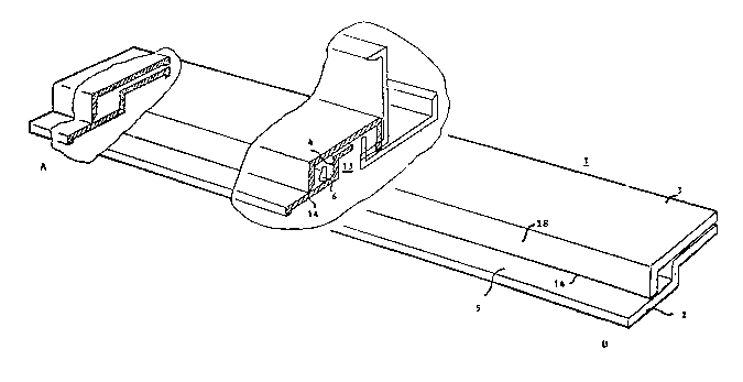
Fig. 1 shows a perspective view of the tearing device according to the
invention, partially in a cross-sectional view in a closed, 90 open and
180 open position of the upper bar respectively;
Fig. 2-7 show a rear view, a top view and a side view respectively, in
partial cross-section, front view and bottom view respectively, o-f the
upper bar;
Fig. a-13 show the same views of the bottom bar;
Fig. 14 shows schernatically a transport pin positioned on the bottom bar.
In the figures the tearing device 1 i9 formed by an oblong ruler-shaped,
profiled bottom bar 2 and a similarly ruler-shaped, profiled upper bar
3, which are obtained by means of injection moulding, for example. The
bottom bar 2 i9 provided with an upstanding positioned guide edge 4 and
upstanding stop pins 6 are provided on the Flat portion 5 which pins serve
to take on the side edges oF computer forms already provided with hole
perforations. Shapa and embodiment of the pins 6 are shown in ~re~ter
,~ 25 detail in Fig. Ill, From which appcars that tho pin i9 partly~eYihr~
at 7 and partly tapering at ~, which shape facilltates the positioning of
the paper sicle etlgc. In order to clrill the relevant hrJles in the mould,
a tE~pering bit can be usod whic h correDponc!s to the t~porincJ pins. The
po~ition af the pin with regEIrtl to thc bottorn bar is ~uch that a closcriptivolinc 19, runnnincJ througl1 the top of tho imacJinary pin cone, i~ perpenclicu-
lar to tho flat portion 5. The lel1gth of the pin~ 6, of which each two
ad3acont onos ar~ located near the extremrJ encl~ of the bottorn bar 2,
depends on the ~lesirecl, optimal pile of paper side edges 9 to be torn
of F. The bottom bar 2 is provided with a pair of recasses in order to form
a hinge joint connection with the upper bar 3, for which purpose a recess
11 is provides. The upper bar 3 contains a similar pair of protrusions
1Z, which have such a diameter and length that the hinge joint connection
is eF-Fected by rneans of a snap-Fastening operation, for example. It can
be seen from Fig. 1 that in case the upper bar 3 is completely open, there
,
~7~62
-4- (~
always remains an oblong recess or a groove, which allows the introduction
of one or mor~ fingers~ so that manual operation of the device is facili-
tated and closing or opening it does not result in jamming one's fingers.
In fig. 4 the pressin~ edge 14 is shown in detail in a cross-section at
05 a wedge angle of about 45. The size oF the wedge angle also depends
on the kind of material used for the bar and on the extent of wear to
which such material is exposed. In general, a wedge angle of between
15" and 85" is used. Fig. 2 shows that the length of part 16 of the upper
bar 3 approximately corresponds with the length of the recess 11 at the
bottom bar 2 and thus the hinge joint action between the protrusions
12 and the holes 10 becomes effective.
The operation of the device 1 is as follows. A pile of paper forms is posi-
tioned over th~ transport/guiding stop pins 6 with its hole perforations
when the upper bar 3 is in open position as in fig. 1. The extrerne paper
side edge then lies almost against the paper guiding stop edge ~. The
pre-perforatrid longitudinal edge of the paper sheet to be separated is
then resting on the flat part 5 of the bottom bar. Furthermore the upper
~/'f ~I e~.
A bar 3 with its sharp edge 14 which does not show a wedge angle at-ett~t~r
end, see fig. 5, as it exceeds the paper sheet edge, i9 pressed down firmly
on the paper line perforation 17 in fig. 11, after which the paper side
edges are seperated from the sheets by a quick tearing of f operation,
parallel to the oblong plane 1~ of the upper bar 3. In order to start a
correct initial tearing operation, the sharp eclge 1ll can slightly and symrne-
trically be curve~l in an upward direction from A to B in fig. 1 so that
the greatest pre~ure force concentrates at the extrerne end~. The embucli-
ment of the device as in Fig. 1-1~ is mer~ly a possible example, without
leavin~ the invcntive idea; sovorE~I constructional modifications can bo
rnad~ having a ~irrlil.lr eFfectivo action.
In a~lditiorl the flat portion 5 in thH ~hown embodiment protrudes con-
skJr)rably pallt tho shape o~l9e 1~. rhis is done in order to give horizontal
support to a pile of forrns to bo soparated, so that the paper side edges
will not easily Dlide of f the tapering pins, which would otherwise hinder
a quick and effective action.