Note : Les descriptions sont présentées dans la langue officielle dans laquelle elles ont été soumises.
~ ~273~9
CABLE S~PPORTING APP~RATUS
FIELD OF THE INVENTION
The invention relates to apparatu~ for supporting
cable and for presenting cable to apparatus for terminat-
ing the cable with a connector. The term "cable" used
herein includes cable, wire or wires and the invention
relates more particularly but not exclu~ively to termin-
ation of flat cable.
BACKGROUND OF THE INVENTION
Machines for automatically or semi-automatically
a~sembly electrical connectors to electrical cable or
wires are known. Current machines often require the
operator to position the cable or wires manually into
the termination area, such positioning involving a sub-
stantial amount of operator dexterity. AB a result,
speed of operation is reduced and risk of making poor
quality connections is increased. Accordingly, it is
desirable to overcome these operational difficulties
making it easier and faster to provide satisfactory con-
nection~.
STATEMENT OF INVENTION
Generally speaking, the problems of the prior art
may be overcome by the preqent invention which provides,
apparatus for supporting cable and ~or presenting cable
to connector applying means, which apparatus comprises
a base and cable support means mounted on the base for
supporting a length of cable, the cablè~support means
being movable relative to the base from a cable loading
position, in which cable loading position, in use, the
~ ' '' , .
"~,' ", ,:
. '
-2-
cable support means is spaced from the connector applying
means, and a working position, in which working position,
in use, cable supported on the cable support means is
presented to the connector applying means for application
of connector means to the cable, wherein the cable support
means comprises a plurality of cable support elements
selectively positionable thereon and an elongate member
on which member the cable support el~ments are selectively
positionable, the apparatus further comprising means for
controlling movement of the elongate member such that a
cable supported on the cable support elements extends
normal to the direction of movement of the elongate member,
wherein the elongate member is supported at least at each
end thereof on arm means extending in the direction of
movement of the elongate member, and the movement con-
trolling means comprises roller means in engagement with
each arm means, the roller means being fixed for rotation
one with another, whereby unit movement of one arm means
will result in unit movement of the other arm means.
s p: ~ ~
'~0
~;~
':
,
'.
734~
-~ -3- AE-289F
_RIEF DESCRIPTION OF THE DRA~ING
By way of example, one embodiment of apparatus
according to the invention will now be described with
reference to the accompanying drawings, in which:
Figure 1 is a general perspective view showing
apparatus according to the invention; and
Figure 2 is a perspective view showing in more
detail a movable frame of the apparatus and a cable
support mounted thereon.
DETAILED DESCRIPTION OF THE PREFERRED EMBODIMENT
. _
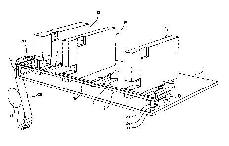
Figure 1 shows schematically a typical
arrangement for cable termination involving three assembly
machines 10 for terminating cable with connectors. The
machines 10 are located on a base 11, on which base 11 i s
mounted a cable support frame 12.
The support frame 12 is movably mounted on end
support assemblies 13, 14 fixed relative to the base 11,
the frame 12 in turn having mounted on it cable support
elements 15, 16 and 17. The cable support elements 15, 16
and 17 are selectively positionable along an elongate bar
18 of the frame 12 such that they may occupy whatever
positions are most conveninent for supporting cable to be
terminated. It will be appreciated that more than three or
indeed less than three`cable support elements may be
present at any one time.
The mounting arrangement of the frame 12 on the
support assemblies 13 and 14 will be described in more
detail with reference to Figure 2 but the arrangement is
such that movement of the frame 12 towards and away from
the assembly machines 10 is in a d;rection perpendicular to
the longitudinal axis of the elongate bar 18, the movement
being illustrated by arrow 19 in Figure l. The frame 12 is
movable from a cable loading position (as shown in Figure
L ~
.. ~
, ~., ', '' ~
' ~ " '
''" ~., ~;
..
' ~'"'' ". ' ~ ' '
'79
1) in which the cable support elements 15, 16 and 17 are remote from the
working area of the assembly machines to a working position where cable
supported on the cable support elements are presented to the assembly machines
10 .
In use, cable, in the illustrated embodiment flat cable 20,
is drawn by an operator from a reel 21 along the length of the elongate
bar 18 over the cable support elements 15 and 16. The cable 20 has a stop
block 22 at its free end and the stop block 22 is engaged behind the face
of the slotted cable support element 17. The operator maintains the cable
20 in slight tension against the cable support element 17 to keep the cable
level along the length oE the bar 18. A short loop in the cable is present
between the reel 21 and the cable support elements to allow for relative
movement between the static reel 21 and the frame 12.
In order to indicate to an operator when the frame 12 is in
the cable loading position, a sensor (to be described in detail with refer-
ence to Figure 2) is provided with, for example, an indicator, either visual
or audible, that the frame is in the cable loading position. A further
sensor (again to be described in detail with reference to Figure 2) is
provided for detecting when the frame 12 is fully and correctly located
into the assembly area of each machine. ~hen in the working position,
the assembly machines are operated to apply connectors to the cable 20.
The central and right hand assembly machines 10 in Figure 1 both apply
a single connector to the cable 20 but the left hand machine 10 (which
can be seen is larger than the other two) applies two connectors and also
includes a central cable cutter so that the cable 20 is cut and the ends
of the cable 20 at the cut are both terminated with a connector. In this
way, the free end of the cable 20 is left with a connector 22 at the end
of each operating cycle.
It will be appreciated that while the apparatus can be used
with manual operation, the sensors for sensing when the frame is in the
cable loading position or in the working position are preferably used to
initiate an automatic assembly operation. Thus when the assembly machines
sense position of the cable in the working position, the assembly operation
of the connectors can be started automatically. To provide added control
flexibility, ~hree operator control buttons 23, 24 and 25 are located on
the end support assembly 13. If the operator presses button 23, the right
hand machine 10 only will apply a connector, and the cable 20 will not
; '""'' ' '"':`'~
.
3~
-- 5 --
be cut. If the button 24 is pressed, the two right hand assembly machines 10
will operate when the working position is reached, and if button 25 is
pressed, all three machines 10 will operate when the working position is
reached. This allows great flexibility in where connectors are applied,
and when the cable is cut by the left hand machine 10. It will be appreciated
that the control permutations could be altered very easily from the arrange-
ment just described.
Likewise, withdrawal of the frame 12 from the assembly machines
to the cable loading position can trigger the sensing devices to initiate
automatic reloading of parts in the working area of each assembly machine
10 in readiness for the next cycle of operation. It is possible to power
drive the movement of the frame 12 and the drawing of the cable along the
frame in a more automated version of the e~uipment than is illustrated
here.
Turning to Figure 2, there is shown in detail how the frame
12 is mounted on the end support assemblies 13 and 14, how a cable support
element is mounted on the bar 18 and the sensing device arrangement.
The frame 12 includes a pair of arms, one of which is illustrated
at 30, extending forwardly over the bar 18. The arm 30 is of angle section
and, similarly to the bar 18, is conveniently of metal. The arm 30 is
supported on a roller assembly consisting of a pair of lower rollers 31
and 32 rotatably mounted on a plate 33 of the end support assembly 13.
The rollers 31 and 32 are rotationally linked by a ribbed drive belt 34
engaging correspondingly profiled outer surfaces of the rollers 31, 32.
To ensure that the arm 30 moves with the belt 34, a bolt 38
secures the arm 30 and belt 38 together, and to keep the arm 30 level,
upper rollers 35, 36 are provided, the rollers 35 and 36 being rotatably
mounted on the plate 33. As an alternative, the arm 30 may be frictionally
engaged with the belt 34 such that rectilinear movement of the arm 30
is translated into rotational movement of the rollers 31 and 32.
The roller 31 is fixed for rotation with a corresponding roller
of the end support assembly 14 by means of a shaft 37. It will be
appreciated that the assemblies 13 and 14 ensure that the bar 18, whatever
its spacing from the assembly machines 10, lies normal to its direction
of travel.
Figure 2 also illustrates a cable support element 40 similar
to the cable support elements 15 and 16 in Figure 1. The cable support
element 40 includes an engagement block 41 slotted to engage over a vertical
portion 42 of the bar 18. Threadedly engaged in the block 41 is a clamping
.,. . . . _j
: ' : -:
-- -:-:.: : . ~ .... . .. :
:'' " ' "' .: '
~273~
~ 6 --
.,
lement 43 rotatable by means of a handle 44. The cable support element
40 can thus be slid along the bar 18 until a desired position is reached
and the clamping element 43 then screwed in to clamp the block 41 against
the bar 18.
It will be appreciated that the design of the bar 18 is such
as to allow a variety of types and numbers of cable support elements and
location units for the cable.
The sensor arrangement is also shown in Figure 2. The cable
loading position is sensed by a microswitch 50 mounted on the plate 33
and a block 51 mounted on the arm 30. Contact between the block 51 and
the microswitch 50 triggers the microswitch 50 to control whatever
operation is desired, or to cause a change of state in an indicator (not
shown). In a similar way, the working position is sensed by a microswitch
52 mounted on the plate 33 and a block 53 mounted on the arm 30. Contact
between the block 53 and the microswitch 52 triggers the microswitch 52
to initiate operation of the assembly machine or machines 10, or another
desired operation or indicator. It will be appreciated that the sensor
arrangement may differ from that just described, and that, for simplicity,
electrical connections from the microswitches 50 and 52 have not been shown.
The advantage of this apparatus is that it offers a simple
means of presenting cable, wire or wires ( it will be appreciated that
any sort of wire or cable may be terminated using the apparatus) in an
orderly and precise manner to machines designed to assemble connectors
and or terminals to the cable, wire or wires. The apparatus ensures
precise alignment of positioning of the cable, wire or wires with the
mechanisms of the machines for assembling the connectors or terminals to
the cable, wire or wires in semi-automatic or operator attended methods
of assembly. Where operator controlled, minimal dexterity is required
and precise positioning and alignment of the parts to be assembled is insured,
hence providing significantly lower risk of unsatisfactory connections and
providing a higher speed of operation.
It will be appreciated that the foregoing description has been
by way of example only and that modifications and alterations may be made
within the scope of the invention. The true scope of the invention is
set forth in the claims appended hereto.
':' ` ': ' :
., ~