Sélection de la langue

Search

Sommaire du brevet 1274121 

Énoncé de désistement de responsabilité concernant l'information provenant de tiers

Une partie des informations de ce site Web a été fournie par des sources externes. Le gouvernement du Canada n'assume aucune responsabilité concernant la précision, l'actualité ou la fiabilité des informations fournies par les sources externes. Les utilisateurs qui désirent employer cette information devraient consulter directement la source des informations. Le contenu fourni par les sources externes n'est pas assujetti aux exigences sur les langues officielles, la protection des renseignements personnels et l'accessibilité.

Disponibilité de l'Abrégé et des Revendications

L'apparition de différences dans le texte et l'image des Revendications et de l'Abrégé dépend du moment auquel le document est publié. Les textes des Revendications et de l'Abrégé sont affichés :

  • lorsque la demande peut être examinée par le public;
  • lorsque le brevet est émis (délivrance).
(12) Brevet: (11) CA 1274121
(21) Numéro de la demande: 1274121
(54) Titre français: ROUE A AUBES POUR POMPES CENTRIFUGES A DEBIT AXIAL ET DEBIT MIXTE
(54) Titre anglais: IMPELLER FOR USE IN AXIAL- AND MIXED-FLOW CENTRIFUGAL PUMPS
Statut: Durée expirée - après l'octroi
Données bibliographiques
(51) Classification internationale des brevets (CIB):
  • F04D 29/28 (2006.01)
  • F04D 29/18 (2006.01)
(72) Inventeurs :
  • BERNAUER, JAN (Allemagne)
(73) Titulaires :
  • KLEIN, SCHANZLIN & BECKER AKTIENGESELLSCHAFT
(71) Demandeurs :
  • KLEIN, SCHANZLIN & BECKER AKTIENGESELLSCHAFT (Allemagne)
(74) Agent: SMART & BIGGAR LP
(74) Co-agent:
(45) Délivré: 1990-09-18
(22) Date de dépôt: 1987-03-11
Licence disponible: S.O.
Cédé au domaine public: S.O.
(25) Langue des documents déposés: Anglais

Traité de coopération en matière de brevets (PCT): Non

(30) Données de priorité de la demande:
Numéro de la demande Pays / territoire Date
P 36 08 229.5 (Allemagne) 1986-03-12

Abrégés

Abrégé anglais


ABSTRACT
The vane of the impeller in a high-speed or
mixed-flow centrifugal pump for the conveying of
liquids which contain high or low concentrations of
strands or strips of vegetable, plastic or other
material has a convex inlet edge whose curvature
increases gradually in a direction radially outwardly
from the axis of rotation at such a rate that the
resultant force of centrifugal force and resistance
encountered by a strip or strand at a particular
point of the inlet edge is invariably tangential to
the respective point of the inlet edge. This ensures
that the strips or strands do not overlie and
circulate with the inlet edge but are entrained by
the resultant force to become separated from the
vane. The inlet angle of the vane in a region which
is remote from the axis of rotation is disposed at
the suction side of the vane; this also contributes
to prevention of accumulation of strips or strands
along the inlet edge.

Revendications

Note : Les revendications sont présentées dans la langue officielle dans laquelle elles ont été soumises.


27210-133
The embodiments of the invention in which an exclusive
property or privilege is claimed are defined as follows:
1. An impeller for an axial- or mixed-flow centrifugal
pump, particularly for conveying a fluid medium which contains
elongated flexible strands and like foreign bodies, comprising at
least one vane rotatable about a predetermined axis and having a
convex inlet edge whose curvature increases in a direction
radially outwardly and rearwardly from said predetermined axis in
such a manner that a resultant force at least substantially
tangential to the inlet edge is generated at each point of the
inlet edge.
2. The impeller of claim 1, wherein the inlet angle of
said vane in a region which is remote from said axis is such that
the stagnation point of the profile of the vane is located at the
suction side of the vane.
- 7 -

Description

Note : Les descriptions sont présentées dans la langue officielle dans laquelle elles ont été soumises.

~2`~
The invention relates to improvements in
axial- and mixed-Elow centrifugal pumps in general,
and more particularly to improvements in impellers
for use in such pumps. Still more particularly, the
invention relates to improvements in the vanes of
impellers for use in axial- or mixed-Elow centrifugal
pumps.
Centrifugal pumps are used for the
conveying of fluids which are devoid of solid
particles as well as for the conveying of fluids,
particularly liquids, which are laden with
impurities. Problems arise when the conveyed fluid
media contain relatively large quantities of
elongated flexible bodies such as strips or strands
of plastic material, grass and the like. Elongated
flexible bodies tend to gather on the inlet edges of
the vanes and to rapidly clog the impeller so as to
necessitate an interruption of the operation.
The impeller becomes inoperative after a relatively
short period of use (e.g., within minutes),
especially if the fluid medium contains a large
quantity of strip-shaped or like Elexible material.
The invention is embodied in an impeller
for use in an axiaL- or mixed-flow centrifugal pump,
particularly Eor conveying a Eluid medium which
contains elongated Elexible strands or strips of
vegetable or other matter tending to clog the
impeller~ of conventional axial- or mixed-flow
centriugal pumps. The impeller comprises at least
one vane which is rotatable about a predetermined

~Z7~
axis and has a convex inlet or suction edge whose
curvature increases gradually rearwardly in a
direction radially outwardly from the predetermined
axis at such a rate that the force R at each point of
the inlet edge is at least substantially tangential
to the inlet edge. The force R is the resultant of
forces F and W wherein F is the centrifugal force
acting upon a foreign body at the respective point oE
the inlet edge and W is the resistance which such
foreign body encounters at the particular point oE
the inlet edye to its progress through the impeller
in a fluid carrier medium, e.g., in a liquid stream.
In accordance with an additional feature of
the invention, the inlet angle of the vane in a
region remote from the predetermined axis is
preferably such that the stagnation point of the
profile of the vane is located at the suction side
of the vane. It has been found that such design of
the vane even further enhances the conveying of
strips, strands or like foreign bodies without the
danger of accumulation of these bodies at the inlet
edge of the vane.
An axial- or mixed-flow centrifugal pump is
preferred for the conveying of fluids which contain
strips or strands of vegetable, plastic and like
material for the reasons oE economy.
The novel features which are considered as
characteristic of the invention are set ~orth in
particular in the appended claims. The improved
centrifugal pump itself, however, both as to its

construction and its mode of operation, together with
additional features and advantages thereoE, will be
best understood upon perusal of the following
detailed desGription of certain specific embodiments
with reference to the accompanying drawing. -
FIG. 1 is a fragmentary front elevationalview of a conventional impeller with strands of
flexible material riding on the illustrated vane in
the region of the inlet edge;
FIG. 2 is a view as seen from the left-hand
side of FIG. 1 and shows a larger accumulation of
elongated flexible material at the inlet edge of the
vane;
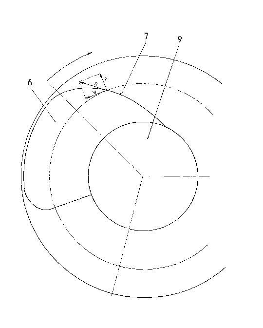
FIG. 3 is a fragmentary front elevational
view of an impeller which embodies the invention; and
FIG. 4 shows the profiles of the vane of
the improved propeller at three different distances
from the axis of rotation of the impeller.
FIGS. 1 and 2 show a portion of a
conventional high-speed axial-flow centrifugal pump
having a hub 3 and one or more vanes 1 having inlet
edges 4 which are likely to accumulate strips or
strands of filamentary and/or fibrous material 2 when
the vane or vanes 1 are rotated in a c:Lockwise
direction (as seen in F'IG. 1). Such material is
contained in a li~uid medium which is conveyed by the
pump. One reason for the accumulation of flexible
material 2 on the vane or vanes 1 is that the ratio
oE peripheral speed to meridlan speed of the vane in
an axial-flow centriEugal pump is normally five or

3L~7a~:~LZ~
six to one~ Thus, the material 2 wiLl be engaged and
entrained by the inlet edge 4 of the vane 1 before it
passes through the impeller. If the inlet edge 4 of
a vane 1 engages a strip or strand 4 of fibrous
material close to the center of gravity of such
material, the material continues to adhere to the
vane and merely circulates around the hub 3. FIG. 1
shows the initial stage of accumulation of strips or
strands 2 of fibrous or filamentary material along
the inlet edge 4, and FIG. 2 shows a much more
advanced stage of accumulation close to or at the
time when the impeller ceases to be operative. Thus,
the large package 5 of filamentary or fibrous
material 2 which overlies and circulates with the
inlet edge 2 renders the impeller and the entire
axial-flow pump inoperative. It has been found that
such clogying of the impeller takes place shortly
after the pump embodying the impeller begins to
convey a Eluid carrier medium with strands or strips
2 of fibrous or Eilamentary material therein.
F'IG. 3 shows a portion of an impeller which
has a hub 9 and at least one vane 6 with a convex
inlet edge 7 having a curvature and inclination as
proposed in accordance with the present invention.
The curvature oE the inlet edge 7 increases gradually
rearwardly from the hub 9 toward the radially
outermost portion of the vane 6 in such a way that
the resultant R of Eorces ~ and W is at least
substantially tangential to the inlet edge 7. The
force F' is the centriEugal force acting on a particle

~z~
of filamentary or fibrous material at a selected
point of the inlet edge 7, and the force W is
indicative of the resistance which a particle or
shred of filamentary or like material encounters at
the particular point of the inlet edge 7 while being
contained in a fluid carrier medium. The magnitude
of a resultant force R which is tangential -to the
inlet edge 7 suffices to ensure that -the elongated
strip, shred or a like particle which is engaged by
the vane 6 at the respective point of the inlet edge
7 is invariably en-trained by such force in the
indicated direction before it can settle on the
vane 6.
FIG. 4 shows the profile of the vane 6 at
three locations I, M and A nearest, more distant and
most distant from the axis of rotation of the
improved impeller. The inlet angle in the radially
outer region A of the vane 6 is selected in such a
way that the staynation point S of the profile is
located at the suction side 8 of the vane 6. This
also contributes to a facilitation of transport of
shreds or strips of fibrous or like materials through
the impeller.
- 6 -
.... . ~

Dessin représentatif
Une figure unique qui représente un dessin illustrant l'invention.
États administratifs

2024-08-01 : Dans le cadre de la transition vers les Brevets de nouvelle génération (BNG), la base de données sur les brevets canadiens (BDBC) contient désormais un Historique d'événement plus détaillé, qui reproduit le Journal des événements de notre nouvelle solution interne.

Veuillez noter que les événements débutant par « Inactive : » se réfèrent à des événements qui ne sont plus utilisés dans notre nouvelle solution interne.

Pour une meilleure compréhension de l'état de la demande ou brevet qui figure sur cette page, la rubrique Mise en garde , et les descriptions de Brevet , Historique d'événement , Taxes périodiques et Historique des paiements devraient être consultées.

Historique d'événement

Description Date
Inactive : Périmé (brevet sous l'ancienne loi) date de péremption possible la plus tardive 2007-09-18
Inactive : CIB de MCD 2006-03-11
Accordé par délivrance 1990-09-18

Historique d'abandonnement

Il n'y a pas d'historique d'abandonnement

Titulaires au dossier

Les titulaires actuels et antérieures au dossier sont affichés en ordre alphabétique.

Titulaires actuels au dossier
KLEIN, SCHANZLIN & BECKER AKTIENGESELLSCHAFT
Titulaires antérieures au dossier
JAN BERNAUER
Les propriétaires antérieurs qui ne figurent pas dans la liste des « Propriétaires au dossier » apparaîtront dans d'autres documents au dossier.
Documents

Pour visionner les fichiers sélectionnés, entrer le code reCAPTCHA :


Pour visualiser une image, cliquer sur un lien dans la colonne description du document. Pour télécharger l'image (les images), cliquer l'une ou plusieurs cases à cocher dans la première colonne et ensuite cliquer sur le bouton "Télécharger sélection en format PDF (archive Zip)" ou le bouton "Télécharger sélection (en un fichier PDF fusionné)".

Liste des documents de brevet publiés et non publiés sur la BDBC .

Si vous avez des difficultés à accéder au contenu, veuillez communiquer avec le Centre de services à la clientèle au 1-866-997-1936, ou envoyer un courriel au Centre de service à la clientèle de l'OPIC.


Description du
Document 
Date
(aaaa-mm-jj) 
Nombre de pages   Taille de l'image (Ko) 
Abrégé 1993-10-12 1 22
Revendications 1993-10-12 1 21
Page couverture 1993-10-12 1 16
Dessins 1993-10-12 4 63
Description 1993-10-12 5 152
Dessin représentatif 2001-07-09 1 11
Taxes 1998-08-18 1 33
Taxes 1997-08-20 1 35
Taxes 1999-08-11 1 24
Taxes 1996-08-19 1 32
Taxes 1995-08-23 1 34
Taxes 1994-08-25 1 26
Taxes 1993-08-25 1 22
Taxes 1992-08-19 1 38