Sélection de la langue

Search

Sommaire du brevet 1274874 

Énoncé de désistement de responsabilité concernant l'information provenant de tiers

Une partie des informations de ce site Web a été fournie par des sources externes. Le gouvernement du Canada n'assume aucune responsabilité concernant la précision, l'actualité ou la fiabilité des informations fournies par les sources externes. Les utilisateurs qui désirent employer cette information devraient consulter directement la source des informations. Le contenu fourni par les sources externes n'est pas assujetti aux exigences sur les langues officielles, la protection des renseignements personnels et l'accessibilité.

Disponibilité de l'Abrégé et des Revendications

L'apparition de différences dans le texte et l'image des Revendications et de l'Abrégé dépend du moment auquel le document est publié. Les textes des Revendications et de l'Abrégé sont affichés :

  • lorsque la demande peut être examinée par le public;
  • lorsque le brevet est émis (délivrance).
(12) Brevet: (11) CA 1274874
(21) Numéro de la demande: 1274874
(54) Titre français: METHODE POUR COMMUNIQUER DE L'ENERGIE THERMIQUE A UN METAL EN FUSION, ET DISPOSITIF CHAUFFANT POUR LA MISE EN OEUVRE DE LADITE METHODE
(54) Titre anglais: METHOD OF SUPPLYING HEAT ENERGY TO A METAL MELT OR THE LIKE AND A HEATING ELEMENT FOR USE WITH SAID METHOD
Statut: Périmé et au-delà du délai pour l’annulation
Données bibliographiques
(51) Classification internationale des brevets (CIB):
  • H05B 3/78 (2006.01)
  • B22D 1/00 (2006.01)
  • H05B 3/03 (2006.01)
  • H05B 3/60 (2006.01)
(72) Inventeurs :
  • EVENSEN, CATO (Norvège)
(73) Titulaires :
  • SCANTHERM A/S
(71) Demandeurs :
  • SCANTHERM A/S (Norvège)
(74) Agent: SMART & BIGGAR LP
(74) Co-agent:
(45) Délivré: 1990-10-02
(22) Date de dépôt: 1986-02-06
Licence disponible: S.O.
Cédé au domaine public: S.O.
(25) Langue des documents déposés: Anglais

Traité de coopération en matière de brevets (PCT): Non

(30) Données de priorité de la demande:
Numéro de la demande Pays / territoire Date
850507 (Norvège) 1985-02-11
852786 (Norvège) 1985-07-11

Abrégés

Abrégé anglais


ABSTRACT
The invention relates to a method and apparatus for
supplying heat energy to a metal weld or similar electroconductive
fluid. According to the method, a rod-like element or elements
are partly immersed in the metal melt or electroconductive fluid.
An end portion of each element is connected to electric power.
The end portion of each element and another end portion disposed
at the opposite end of each element consist of an electrocon-
ductive material, while a relatively long center portion of each
element consists of an electrically resistant material. A segment
of each element which is contiguous with at least the portion of
each element which is comprised of electrically resistant
material, is coated with an electrically insulated heat conductive
coat which allows heat transfer from the electrically resistant
portion of each element to the melt. The heating elements for the
implementation of the method are disposed so that the end portions
project from the melt to allow connection to an electric power
source. The end portion of each element consists of a material
that is a good electric conductor, and the longer center portion
is composed of an electrically resistant material. The coating
consists of a material made from one or more oxides of metal or
metalloids.

Revendications

Note : Les revendications sont présentées dans la langue officielle dans laquelle elles ont été soumises.


- 6 - 26955-4
THE EMBODIMENTS OF THE INVENTION IN WHICH AN EXCLUSIVE
PROPERTY OR PRIVILEGE IS CLAIMED ARE DEFINED AS FOLLOWS:
1. A method for supplying heat only to a metal melt,
comprising the steps of:
(a) providing a metal melt;
(b) supplying a core which is composed of an electri-
cally resistive material which is capable of withstanding tempera-
tures exceeding the melting point of a metal to which heat is to
be supplied;
(c) providing a means for conducting electricity to
said core;
(d) providing a means for conducting electricity from
same core;
(e) coating said core with a coating which is elec-
trically insulating and which has a relatively high heat conduc-
ting capacity; and
(f) immersing said core of step (e) in the metal melt.
2. A method as claimed in claim 1, wherein in step (b),
said core is composed of silicon carbide;
in step (c), said means for conducting electricity to
said core being provided as a crystalline form of silicon carbide;
and
in step (e), said coating being provided as aluminum
oxide and silicon oxide.
3. An apparatus for providing heat energy only while
immersed in a metal melt comprising:

- 7 - 26955-4
a core, said core being composed of an electrically
resistive material;
a means for conducting electricity through said core
to cause electrically resistive heating of said core;
and a coating on said core, said coating being elec-
trically insulating, heating conductive, and metal resistant;
said coating being selected from a group including
one or more oxides of metals and/or metalloids.
4. An apparatus as claimed in claim 3, wherein said coat-
ing comprises aluminum oxide, and silicon oxide.
5. An apparatus as claimed in claim 4, wherein said core
comprises at least two elongated bodies.
6. An apparatus as claimed in claim 5, wherein said two
elongated bodies are non-colinear, and which are connected together
by an electrically-conductive member.
7. An apparatus as claimed in claim 5, wherein said
core includes three elongated bodies which are connected together
by electrically conducting members, and wherein said three bodies
are mutually non-colinear.
8. A heating element for supplying heat energy only while
immersed in a metal melt, comprising:
an elongated core; said core being composed of silicon
carbide, and being electrically resistive;
an upper end portion connected to an upper portion of

- 8 - 26955-4
said core, and a lower end portion connected to a lower portion
of said core; said upper end portion and said lower end portion
being composed of silicon carbide in crystalline form; said
silicon carbide in crystalline form being a relatively good con-
ductor of electricity and of relatively low electrical resistance
compared to said core; and
a coating on said core composed of a mixture of two
or more oxides selected from the group including aluminum, zircon-
ium, silicon, and magnesium.

Description

Note : Les descriptions sont présentées dans la langue officielle dans laquelle elles ont été soumises.

'7~
- 1 - 26955-4
The present invention rela-tes to a method of maintaining
metal or the like in a melted state in a container by the aid of
electric resistance heating. Furthermore, the invention relates
to a heating element for use with said method.
It is previously known to supply energy to a metal melt
by using electric resistance elements which may, in principle, be
arranged in two different manners, i.e. either on top of the melt
surface or in a tube or another sleeve-shaped body -t~a-t is partly
immersed in the metal melt. Conventional materials in such elec-
tric resistance elements are alloys of chrome-nickel and iron-
aluminium, as well as e.g. silicon carbide, graphite, and
molybdenum-silicon.
With the method comprising electric resistance elements
provided on top of the metal melt surEace, energy from said resis-
tance elements is transferred to the metal melt by heat radiation
onto the melt surface. This means that the container per se for
the metal melt must be dimensioned with equal consideration to
heat energy transfer and the space required by -the actual produc-
tion process. This will, in turn, result in a metal bath with a
content of molten metal considerably larger than necessary for the
production process per se. Due to this, much capital will be
locked-up, e.g. as in the case of top heated galvanizing furnaces.
Additional disadvantages of this method are that the resistance
elements are not very resistan-t to metal spatter from the metal
bath, and that any protection of the resistance elements against
such metal spatter will result in reduced heat transfer rom said
- elements to the metal melt.
V,j ~; r

~.Z7g~7~
- la - 26955-4
In another known method the metal element is supplied
with energy by heating elements/resistance elements, preferably
shaped as rods, and provided in a tube with a bottom or in another
sleeve-shaped body that is partly immersed in the metal melt, and
where there is no electroconductive contact between the resis-
tance element(s) and said sleeve. With this method

- 2 - ~6955-4
heat is transferred by radiation from the resistance element to
said sleeve from which heat conduction occurs in the metal melt.
Heating elements of the above kind are disclosed,
inter alia in U.K. Patent No. 1,027,163 and U.S. Patent No.
4,132,886. Said sleeves may be manufactured from different kinds
of material. When the material comprises metal alloys the sleeve
temperature will be limited to a relatively low level, causing a
reduction of the amount of energy transfer that could otherwise
be utilized from said resistance elements. Another disadvantage
la of metal alloys is that they are not very resistant to metal
melts, e.g. from zinc and aluminium. Tubes or sleeves made from a
material based on, e.g. graphite, silicon carbide, silicon nitride,
or aluminium nitride resist higher temperaturesl and may also be
resistant to molten metals. In practice, however, it proved
difficult to achieve a satisfactory tight tube or sleeve in said
materials. This will, inter alia, result in the fact that the
outer tube or sleeve surface facing the metal melt is subjected
to oxygen resulting in an oxidation of said outer surface and/or
the molten metal adjacent said outer surface. The oxide layer,
~d thus, formed has a heat insulating effect and will, thus, reduce
the amount of transferred energy. Another disadvantage of such
tubes or sleeves is that the heat exchange constancy may be poor.
According to the present invention a new method of
supplying a metal bath or a similar electrically conductive fluid
with heat energy is provided which eliminates the above mentioned
disadvantages of the known technology of the art to a considerable
degree.
;~:

3 26955-4
According -to one aspect, the present invention provides
a method for supplying heat only to a metal melt, comprising the
steps of:
(a) providing a metal melt;
(b) supplying a core which is composed of an electri-
cally resistive material which is capable of withstanding
temperatures exceeding the melting point of a metal to which heat
is to be supplied;
Ic) providing a means for conducting electricity to
la said core;
(d) providing a means for conducting electricity from
same core;
(e) coating said core with a coating which is elec-
trically insulating and which has a relatively high heat conducting
capacity; and
(f) immersing said core of step (e) in the metal melt.
According to another aspect, the present invention
provides an apparatus for providing heat energy only while
immersed in a metal melt comprising: a core~ said core being com-
posed of an electrically resistive material; a means for conducting
electricity through said core to cause electrically resistive
heating of said core; and a coating on said core, said coating
being electrically insulating, heating conductive, and metal
resistant; said coatlng being selected from a group including one
or more oxides of metals and/or metalloids.
The electric resistance material of the core may be of

~.~'74~37~
- 3a - 26955-~
a conventional kind, and in metal baths, e.g. in a zine bath or
an aluminum bath, the eleetrie resistanee material is preferably
a semi-eonduetor material on the basis of graphite or silicon
carbide. In principle the coating material should be a material
showing high insulating capability, good heat eonduetivity, high
heat exchange toleranee, high temperature toleranee, and high
resistance to the metal bath. Materials that are suitable in this
eonneetion are materials essentially eonsisting of oxides of metals
and/or metalloids, preferably oxides of aluminium, zine, zireonium,
1~ silicon/ and magnesium. The material of the end portions of the
core, the so called cold ends, may in principle consist of any
highly electroeonduetive material resistant under the prevailing
eonditions. The eore may be formed of two or more elongate
bodies joined by means of an eleetric resistance material, e.g.
the same material as that of the eore, or it may consist of a
highly eleetroconduetive material, e.g. the same material as that
o~ the so ealled eold ends.

8~
The heating element açcording to the present invention is
immersed in the molten me-tal in such a manner that only the
end portions of the rod-like element arms being provided with
a coat to a certain level above the me~-al bath will project
from said metal bath. When the ends of the elements projecting
~rom the bath are connected to a source of power the immersed
portion of the elemen-ts essentially consisting of said electric
resistance material and a coating, form the hot zone of
the elements. With this kind of heating element the metal bath
is supplied with heat energy by direct heat conduction.
The present invention will now be disclosed in more detail
with reference to three embodiments shown in associated figures
of the drawing, wherein
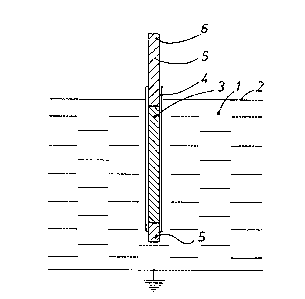
Figure 1 is a sectional view o~ a rod-like heating element
partly immersed in a metal bath;
Figure 2 is a sectional view of a two-armed heating element
partly immersed in a metal bath; and
Figure 3 is a sectional view of a three-armed heating element
partially immersed in a metal bath.
In Figure 1 a metal bath is designated l,and the surface of
said bath is designated 2. A heating element is immersed in
said metal bath 1, and said heating element consists of a core
3 of silicon carbide showing relatively high electric resistance.
At both ends of said silicon carbide rod 3 end portions 5 are
provided said end portions also consisting of a silicon
carbide material but in a crystalline form which renders said
material a good electrical conductor. Said two end portions 5
are called the cold ends of the heating elements. The entire
core 3 and part of the so called cold ends are coated with a
coat 4 essentially consisting of aluminum oxide and silicon
oxide. The source of power (not shown) is connected to the

~ ~'7~8~
heating element at its upper cold end 6. It will appear that
the hot zone o~ said heating element is provided by the
portion of the element containing the core. When said heat-
ing element is connected to a source of power an elec-tric
connection will, thus, be established via the metal bath bet-
ween the lower cold end of the heating element a~d, e.g. a
neutral electrode. Thus, there wil] be a certain voltage
difference between the two cold ends of the heating element.
Due to the Eact that the coat forms an electrical insulation
against the liquid me-tal said vol-tage difference will be con-
verted into heat energy in the hot zone of said heating
element, said zone showing high electric resistance.
In Figures 2 and 3 a metal bath is designated 11 and 12 design-
ates the surface of said bath. The rod-like arms consist of
r~sistance material 13, in -the present embodiment being
silicon carbide, and 15 designates the cold end here formed
from silicon carbide, but in a crystalline form rendering the
material a good electric conductor. The rod-like arms are
joined into electroconductive connections by the aid of
a connecting member 16, in the present embodiment made from
the same material as the cold ends 15. The coating material 14
in the present case consisting essentially of aluminium oxide
and silicon oxide, covers -the entire immersed portion of the
element as well as part of the cold ends 15 projecting from
the bath. In the embodiment shown in Figures 2 and 3 those
portions of the coid ends provided below and ~immediately above
the surface of the metal bath are provided with coating
material.
The source of power, not shown in Figures 2 and 3, is connect-
ed with the end portions 15 pro~ecting from the bath. The
hot zone of the heating elements, as shown~consists of the
portion of the heating element where the electric resistance
material is provided.

Dessin représentatif
Une figure unique qui représente un dessin illustrant l'invention.
États administratifs

2024-08-01 : Dans le cadre de la transition vers les Brevets de nouvelle génération (BNG), la base de données sur les brevets canadiens (BDBC) contient désormais un Historique d'événement plus détaillé, qui reproduit le Journal des événements de notre nouvelle solution interne.

Veuillez noter que les événements débutant par « Inactive : » se réfèrent à des événements qui ne sont plus utilisés dans notre nouvelle solution interne.

Pour une meilleure compréhension de l'état de la demande ou brevet qui figure sur cette page, la rubrique Mise en garde , et les descriptions de Brevet , Historique d'événement , Taxes périodiques et Historique des paiements devraient être consultées.

Historique d'événement

Description Date
Inactive : CIB de MCD 2006-03-11
Le délai pour l'annulation est expiré 2004-10-04
Lettre envoyée 2003-10-02
Inactive : TME en retard traitée 1997-10-24
Lettre envoyée 1997-10-02
Accordé par délivrance 1990-10-02

Historique d'abandonnement

Il n'y a pas d'historique d'abandonnement

Historique des taxes

Type de taxes Anniversaire Échéance Date payée
TM (catégorie 1, 7e anniv.) - petite 1997-10-02 1997-10-24
Annulation de la péremption réputée 2002-10-02 1997-10-24
TM (catégorie 1, 8e anniv.) - petite 1998-10-02 1998-10-02
Annulation de la péremption réputée 2002-10-02 1998-10-02
Annulation de la péremption réputée 2002-10-02 1999-09-20
TM (catégorie 1, 9e anniv.) - petite 1999-10-04 1999-09-20
Annulation de la péremption réputée 2002-10-02 2000-09-25
TM (catégorie 1, 10e anniv.) - petite 2000-10-02 2000-09-25
TM (catégorie 1, 11e anniv.) - petite 2001-10-02 2001-09-07
Annulation de la péremption réputée 2002-10-02 2001-09-07
Annulation de la péremption réputée 2002-10-02 2002-09-23
TM (catégorie 1, 12e anniv.) - petite 2002-10-02 2002-09-23
Titulaires au dossier

Les titulaires actuels et antérieures au dossier sont affichés en ordre alphabétique.

Titulaires actuels au dossier
SCANTHERM A/S
Titulaires antérieures au dossier
CATO EVENSEN
Les propriétaires antérieurs qui ne figurent pas dans la liste des « Propriétaires au dossier » apparaîtront dans d'autres documents au dossier.
Documents

Pour visionner les fichiers sélectionnés, entrer le code reCAPTCHA :


Pour visualiser une image, cliquer sur un lien dans la colonne description du document. Pour télécharger l'image (les images), cliquer l'une ou plusieurs cases à cocher dans la première colonne et ensuite cliquer sur le bouton "Télécharger sélection en format PDF (archive Zip)" ou le bouton "Télécharger sélection (en un fichier PDF fusionné)".

Liste des documents de brevet publiés et non publiés sur la BDBC .

Si vous avez des difficultés à accéder au contenu, veuillez communiquer avec le Centre de services à la clientèle au 1-866-997-1936, ou envoyer un courriel au Centre de service à la clientèle de l'OPIC.


Description du
Document 
Date
(aaaa-mm-jj) 
Nombre de pages   Taille de l'image (Ko) 
Page couverture 1993-10-13 1 16
Abrégé 1993-10-13 1 29
Revendications 1993-10-13 3 69
Dessins 1993-10-13 1 20
Description 1993-10-13 7 213
Dessin représentatif 2001-09-20 1 5
Avis concernant la taxe de maintien 1997-10-30 1 178
Quittance d'un paiement en retard 1997-11-03 1 171
Avis concernant la taxe de maintien 2003-11-27 1 174
Taxes 1998-10-02 1 37
Taxes 1997-10-24 2 63
Taxes 1996-10-09 2 61
Taxes 1994-07-15 1 30
Taxes 1993-09-22 1 39
Taxes 1995-09-29 1 36
Taxes 1992-04-16 1 30