Note : Les descriptions sont présentées dans la langue officielle dans laquelle elles ont été soumises.
~X'75138
SPECIFICATION
ELECTRO~AGNETIC RELAY
BACXGROUND OF THE INVENTION
1. Field of the invention
The present invention relates to an electromagnetic relay,
and more particularly to an electromagnetic relay having an
armature block movable in a linear path between two contact
operating positions.
2. Description of the prior art
Electromagnetic relays with a linearly movable armature
block are known in the art as disclosed, for example, in U.S.
Pat. No. 4,538,126 issu~d on Aug. 27, 1987 to Bando. In this
prior art relay, the armature block is held between a pair of
separate balancing springs each extending in parallel relation
with each other and supported loosely on a relay base. The
separate provision of the balancing springs in the prior art
relay requires to mount the springs individually on the relay
base, making it rather complicate to assembly the balancing
springs. Further, the loose connection of each balancing
spring to the relay base is very likely to induce fluctuation
in the spring force exerted on the armature block, which
involves sophisticated technique to obtain a precisely tuned
balancing force required for the armature block, in addition
to the effect that the separately mounted springs exert the
spring forces individually to the armature block. In these
respects, the prior art relay is not satisfactory for
-- 2
providing convenient assembl~ of the balancing spring as well
as for providing a consistent balancing e~fect to the armature
block.
SUMMARY OF THE INVENTION
The above problems have been eliminated in the present
invention which provides an improved electromagnetic relay.
The relay in accordance with the present invention comprises a
base for mounting thereon an electromagnet block and contact
means and an armature block. The armature block is
magnetically coupled to the electromagnet block in such a
manner that it is magnetically driven thereby to move linearly
between two operating positions for actuating the contact
means into open and closed contact conditions. The
characterizing feature of the present invention resides in
that the armature block is supported on the base by means of a
U-shaped balancing spring which has a pair of parallel spring
arms in the form of a spring leaf and a web integrally
bridging the parallel spring arms at one end of each arm. The
balancing spring is secured to the base at its web and carries
the armature block with the other end of each spring arm being
connected to each of the opposite sides of the armature block
at a point an equal distance from the one end of each spring
arm such that the parallel spring arms and web are cooperative
with the armature block to define a substantial parallelogram,
whereby allowing the armature block to swing in a linear path
parallel with the length of the web. The utili~ation o~ the
~L~75~38
single balancing spring of U-shaped configuration is
advantageous in reducing the number of spring components and
facilitating the assembly thereof yet ensuring a stable and
accurate balancing effect on the armature block. Further,
since the U-shaped spring holding the armature block bet~een
the other ends of the spring arms is secured to the relay base
at its web, the armature block and the biasing spring
combination can be easily assembled at once in the relay
structure simply by fixing the web to the relay base.
Accordingly, it is a primary objPct of the present
invention to provide an improved electromagnetic relay which
is capable of reducing the number of spring components and
facilitating the assembly, yet assuring to give a stable and
reliable balancing spring characteristic to the armature
; 15 movement.
In a preferred form, the U-shaped balancing spring includes
an integral bridge segment which bridges between the other
ends of the spring arms at points closely adjacent to the
juncture of the spring arms with the armature block. With
this bridge segment, the balancing spring completes the
parallelogram by itself ko further improve a consistent
balancing spring characteristic responsible for the desired
linear movement of the armature block.
It is therefore another object of the present invention to
provide an impxoved electromagnetic relay in which the
balancing spring is reinforced by the bridge segment to
.
" ~75i~3~3
-- 4
provide a consistent balancing spring effect on the armature
block.
The bridge segment can also serve as another support for
the armature block to securely hold the armature block in
cooperation with the other end of each spring arm. To this
end, the bridge segmant is secured to the upper surface of the
armature block by a suitable adhesive. Preferably, the bridge
segment is in the form of a flat member which is wider at its
middle portion than at the juncture ends with the spring arms
for giving a greater adhesion area to the armature block,
which is therefore a further object of the present invention.
The balancing spring further includes an anchor plate which
extends from the web in the direction generally perpendicular
to the plane of the spring arms for insertion into a
complementary slot formed in the relay base. Either side of
the anchor plate is finished as a vertical guide edge
extending in perpendicular relation to the length of the web
in order that, during the assembly oE mounting the armature
block on the relay base by inserting the anchor plate into the
correspondingly shaped slot, the vertical guide edges act to
guide the armature block held by the spring vertically down to
: the relay base, preventing any lateral displacement of the
armature block and movable contact means carried on the
lateral sides and extending longitudinally thereo~. Thus, the
vertical edges of the anchor plate can ensure easy and exact
alignment between the movable contact means carried on the
~75~38
armature block and the stationary contact means mounted on the
relay base.
It is therefore a still further object of the present
invention to provide an improved electromagnetic relay in
; 5 which the armature block with the movable contact means can be
easily assembled to the relay base, while ensuring exact
alignment between the movable contact means on the armature
block and the stationary contact means on the relay base.
The present invention also discloses a further advantageous
feature for adapting the relay in a RF circuit. For this
purpose, a RF shield is mounted on the relay base to surround
the contact means composed of the movable contact means and
the stationary contact means. The RF shield has at least one
ground terminal extending outwardly of the base and so
arranged to come into electrical contact with the movable
contact means in the open contact condition, enabling to
electrically isolate one contact member from the adjacent
contact member for elimination of RF signal leakage, which is
therefore a still further object of the present invention.
These and still other objects and advantages of the present
invention will bacome apparent from the fol~owing detailed
description of the preferred embodiments of the present
invention when taken in conjunction with the acco~panying
drawings.
BRIEF DESCRIPTION OF THE DRAWINGS
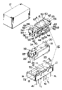
Fig. 1 is an exploded perspective view of an
5~3~3
electromagnetic relay in accordance with a first embodiment of
the present invention;
Fig. 2 is a top view partly in section of the above relay;
Fig. 3 is a cross sectional view taken along line 3 - 3 of
Fig. 2;
Fig. 4 is an exploded perspective view of an electromagnet
block, a RF shield, and a base utilized for the above relay;
Fig. 5 is a top view of the RF shield;
Fig. 6 is an exploded perspective view of a first modification
of the relay of Fig. 1;
Fig. 7 is an exploded perspective ~iew illustrating an
integral combination of an armature block and a kalancing
spring in accordance with a second modification of the relay
of Fig. 1;
; 15 Fig. 8 is an exploded perspective view o~ an
electromagnetic relay in accordance with a second preferred
embodiment of the present invention; and
Fig. 9 is a top view of the relay of Fig. 8.
DESCRIPTION OF ~HE PREFERRED EMBODIMENTS
First embodiment <Figs. 1 to 5>
Referring now to Figs. 1 to 4, there is shown an
electromagnetic relay in accordance with a first embodiment of
the present invention. The relay is of a polarized type which
comprises a mount base 10 for mounting thereon an electro-
magnet block 20, a contact assembly 40, and an armature block
50. The base l0 is molded from an electrically insulative
~7~7~3~3
-- 7
plastic material to have a recess which is divided by a
partition wall 11 into chambers 12 and 13, one for receivlng
the electromagnet block 20 and the other for the contact
assembly 40. The partition wall 11 extands full distance
between the opposed end walls 14 and 15 and is integrally
connected at its ends thereto. A cover 17 of like insulative
material fits over the base 10 to encapsulate the entire relay
structure.
The electromagnet block 20 comprises a center core 21 and a
pair of side and bottom yoke legs 23 and 24 each extending in
parallel with the core 21 and coupled at its one end to the
adjacent end of the core 21. An excitation coil 30 is placed
around the core 21 through a bobbin 31 with the free end of
the core 21 left exposed to define thereat a first pole end
22. As best shown in Fig. 4, the side and bottom yoke legs 23
and 24 extend in spaced relation respectively with the one
side face and the bottom face of the core 21. The upper half
portion of the free end of the side yoke leg 23 is cut out r
while the lateral edge of the free end of the bottom yoke leg
23 remote from the side yoke member 23 ~s upturned to define
thereat a second pole end 25 which is coactive with the first
pole end 22 of the center core 21 to define a magnetic gap. A
residual plate 26 is attached to the side face of the core 21
in confronting relation with the cutout of the side yoke leg
23. The ends of the excitation coil 30 are wired respectively
to coil terminals 32 and 33 each supported to the extension of
,~ .
~5~3~3
the bobbin 31 to extend outwardly through the bottom of the
base 10 when assembled.
The armature block 50 include~s a generally rectangular flat
member 51 of electrically insulative plastic material which
carries at its longitudinal end a pair of pole plates 52 and
53 and a permanent magnet 54. The pole plates 52 and 53 have
their upper end portions embedded in the flat member 51 with
the permanent magnet 54 interposed therebetween so as to be
magnetized to opposite polarityO The permanent magnet 54 is
entirely received within the thickness of the flat memb~r 51,
while the lower ends of pole plates 52 and 53 project
downwardly from the flat member 51 for magnetic coupling with
; the pole ends of the electromagnet block 20. Integrally
formed on one lateral side of the flat member 51 are a pair of
longitudinally spaced ledges 55 each ormed with a bottom
cavity (not shown) for connection with each of a pair of
elongated movable contact springs 4~. Each of the movable
contact springs 42 is held at its center by a vertical prop ~4
of electrical insulative material and is connected to the
armature block 50 with the upper end of the prop 44 fitted in
the bottom cavity of each ledge 5~ so that each contact spring
42 extends horizontally in parallel relation with the
longitudinal axis of the armature block 50. As shown in Figs.
1 and 2, the movable contact springs ~2 are longitudinally
staggered in such a manner as to overlap the adjacent ends
thereof in spaced relation. Formed in the top of the flat
5~3~3
member 51 adjacent to each ledge 55 is a circular sink 56 for
receiving a suitable adhesive fluid. The adhesive fluid
supplied to the sink 56 flows through a trough 57 and a top
pit 58 in each ledge 55 into the bottom cavity thereof for
enhanced coupling between the flat member 51 and the prop 44
of each movable contact spring 420
The armature block 50 thus constructed to carry the movable
contact springs 42 is supported on the base 10 by means of a
U-shaped balancing spring 60 so as to be mo~able along a
linear path perpendicular to the longitudinal axis of the
armature block 50 between two contact operating positions.
The U-shaped spring 6~ has a pair of parallel spring arms 61
and 62 integrally connected at one ends by a web 63. The
spring 60 is struck from a metal sheet and bent into the U-
shaped configuration in which the parallel spring arms 61 and62 are allowed to move resiliently within the plane thereof
while the web 63 is restrained from moving resiliently within
that plane. The spring arms 61 and 6~ extend along the
lateral sides of the armature block 50 and are fixed at the
respective free end portions thereto by means of pins 59 each
of which is integral with the flat member 51 and extends
through each spring arm 61, 62 to be welded thereover. The
pins 59 connect the spring arms 61 and 62 to the flat member
51 at an equal distance from the web 63 such that the parallel
spring arms 61 and 62 and the web 63 are cooperative with the
flat member 51 to form a parallelogram, allowing the armature
75~38
- 10 -
block 50 to move linearly in the lateral direction as
resiliently flexing the parallel arms 61 and Ç2. The
balancing spring 60 and the armature block 50 held between the
spring arms 61 and 62 thereof are together mounted on the base
10 by means of an anchor plate 65 which extends downwardly
from the web 63 with its top portion secured to the adjacent
ends of the spring arms 61 and 62. The anchor plate 65, which
may be alternatively integral with the web 63, projects in
vertical relation with respect to the plane of the movement of
the armature block 50 and is snugly received in a correspond-
ingly shaped slot 16 formed in the end wall 15 of the base 10.
The lateral edges 66 of the anchor plate 65 and the
corresponding inner walls of the slot 16 are made vertical
with respect to the length of the web 63 or the lateral
direction of the armature block 50 so that, during the
insertion of the anchor plate ~4 into the slot 16, the
armature block 50 can be g~ided straight down to the base 10
without lateral movement or fluctuation, contributing to exact
and easy positioning of the movable contact springs into a
predetermined relation to stationary contact pins 41 on the
base 10. A bridge segment 64 integrally bridges between the
spring arms ~1 and ~2 at points corresponding to the pins 5g
so as to reinforce the parallelogram as well as to serve as an
additional element for coupling with the armature block 50.
To this end, like adhesive fluid is utilized for adhering the
bridge segment 64 to the top of the flat member 51, the
~S~l38
adhesive being supplied to and received in a shallow recess 67
in the top of the flat member 51. Thus, the weight of the
armature block 50 is mainly supported by the bridge segment 64
while it is drivingly supported by a pair of the parallel
spring axms 61 and 62. The above bridge segment 64 is
particularly advantageous in that it can retain the
parallelogram even when either o:r both of the spring arms 61
and 62 might suffer from deformation at the connections with
the pins 59.
The stationary contact pins 41 are composed of three
longitudinally aligned pins which extend vertically through
the bottom of the chamber 13 of the base 10 in an equally
spaced relation to each other, as best shown in Fig. 2, and
which are cooperative with the movable contact springs 42 to
define the contact assembly 40. One of the movable contact
spring 42 is disposed on one side of one pair of the adjacent
two stationary contact pins 41 in an engageable relation
therewith at its longitudinal ends, while the other movable
contact spring 42 is on the opposite side of the other pair of
the adjacent two stationary contact pins 41 in an engageable
relation therewlth at its longitudinal ends. The movable
contact springs 42 are so arranged that one movable contact
spring 42 is in closed contact condition with the
corresponding stationary contact pins 41 when the other spring
42 in open contact condition.
As shown in Fig. 2, the armature block 50 mounted on the
38
base 10 by the balancing spring 60 is magnetically coupled to
the electromagnet block 20 located therebelow in such a way
that the first pole end 22 of the core 21 e~tends between the
pole plates 52 and 53 and at the same time that the pole plate
52 extends between the first pole end 22 and the second pole
end 25. Thus, upon deenergization of the excitation coil 30
the armature block 50 is held stable in a first contact
operative position where the pole plates ~3 and 52 are
attracted respectively to the first and second pole ends 22
and 25 to complete the magnetic flux of the permanent magnet
54. In this position, one of the movable contact springs 42
is actuated into closed condition and the other spring 42 into
open condition. When the excitation coil 30 is energi ed to a
particular polarity, the armature block ~0 responds to move
linearly into a second contact operatlve position for
reversing the contacts where the pole plate 52 is attracted to
the first pole end 22 of the core 21 just magnetized to the
opposite polarity. In this way the armature block S0 is
driven to move linearly between the two contact operating
positions as reslliently flexing the spring arms 61 and 62 of
the balancing spring 60. During this linear movement of the
armature block 5~, an element 34 projecting integrally from
the coil bobbin 31 and slidably received in an opening 68
serves as an aid for smoothly guiding the armature block 5~ in
its linear path.
The contact assembly 40 composed of the stationary contact
~ 75~l3~
pins 41 and the movable contact spring 42 is surrounded by a
RF (radio-frequency) shield 70 with a plurality of spaced
ground pins 71. The RF shield 70 is shaped from an electrical
conductive sheet into a rectangular shape and received in the
chamber 13 in intimate contact with the inner walls thereof
and with the ground pins 71 extending outwardly through the
bottom wall of the base 10. Projected on the inner surface of
the RF shield 70 at positions corresponding to the stationary
contact pins 41 are respective nubs 74 on which the ad~acent
movable contact springs 42 rest to be grounded when they come
into open condition, ensuring to electrically isolate the one
movable contact spring 42 in open condition from the other
movable contact spring 42 and the associated circuit.
Integrally formed with the RF shield 70 is an adjusting stud
72 which extends upwardly past the electromagnet block 20 to
be enagageable with an integral extension 69 of the spring arm
61. As necessary, the adjusting stud 72 is twisted or bent to
positively engage the extension 69 for biasing the balancing
spring 60 in one direction in order to obtain a desired
balancing effect upon the armature block 50.
Fig. 6 shows a first modification of the above embodiment
which i5 identical in construction and operation to the first
embodiment except that an improved bridge segment 64a is
utilized to bridge the free ends of spring arms 61a and 62a of
a balancing spring 60a, and except that the adjusting stud 72
and the associated parts are eliminated. For an easy
~LZ75~
- 14 -
reference purpose, like numerals are employed to designate
like parts. The bridge segment 64a of the modification is
shape~ to have a flat middle of a greater width than at the
juncture ends with the spring arms 61a and 62a. The increased
width of the bridge segment 6~a assures an increased bonding
surface area with the top of the armature block 50 for
enhanced bonding therebetween by the adhesive.
Fig. 7 shows a second modification of the ~irst embodiment
in which a balancing spring 60b and an armature block 50b are
integrally combined to provide a combination block 80 of one-
piece construction. The other structures of the relay are
identical to the first embodiment and therefore further
duplicated explanation is elimiated. The combination block 80
is molded from an electrically insulative material in which
the armature block 50b and an anchor plate 65b are thick-
formed to be of rigid construction. The armature block 50b
and the anchor 65b are connected by a pair of integral members
61b and 62b which are thin-formed to define parallel spring
arms of the balancing spring 60b. The spring arms 61b and 62b
are interconnected by the upper end of the anchor plate 65b,
which defines the web 63b of U-shaped configuration, and are
cooperative with the integral armature block 50b to define a
parallelogram, whereby allowing the armature block 50b to move
linearly in the lateral direction as resiliently flexing the
spring arms 61b and 62b, in the same manner as in the first
embodiment. The armature block 50b is formed with an opening
~7~;~3t3
-- 15 --
56b for receiving together a pair of pole plates 52b and 53b
and a permanent magnet 54b and is formed further with a ledge
55b ~or receiving a set of movable contact springs 42b.
Second embodiment <Figs. 8 and 9>
Referring to Figs. 8 and 9, a polarized electromagnetic
relay in accordance with a second embodiment of the present
invention is shown to comprise a base 110, an electromagnet
block 120, a contact assembly 140, and an armature block 150.
The electromagnet block 120 is received in an elongated
chamber 112 in the base 110 which is surrounded by side walls
113 and end walls 114 and 115. Mounted on each side wall 113
is a set of longitudinally spaced contact assemblies 140 each
composed of a stationary contact 141 and a movable contact
spring 1~2. These contacts 141 and 142 have respective
terminal lugs 145 and 146 extending downwardly through the
side wall 113. One end wall 115 of greater height than the
opposed wall 114 is formed in its top with a slot 116 for
mounting together the combination of the armature block and a
balancing spring 16~.
The electromagnet block 120 includes a generally U-shaped
core 121 with opposed pole ends 122 and 125 at its both ends.
~n excitation coil 130 carried on a bobbin 131 is placed
around the center portion of the core 121 with the opposed
pole ends 122 and 125 projecting upwardly from the ends of the
bobbin 131. The coil ends of tha excitation coil 130 are
connected to respective coil terminals 132 and 133 extending
75~38
- 16 -
downwardly through the bobbin 131 and through the bottom of
the chamber 112 when assembled.
The armature block 150 comprises a generally rectangular
flat member 151 of electrically insulati~re material carrying
at each longitudinal end a perma:nent magnet 154 interposed
between a pair of pole plates 152 and 153. The upper ends of
the pole plates 152 and 153 are fitted together with the
permanent magnet 154 within each of vertical holes 156 in the
longitudinal ends of the flat member 151 so as to project the
lower ends of the pole plates 152 and 153 which are polari~ed
to opposite polarity by the permanent magnet 154O Between the
pole plates 152 and 153 at each end of the armature block 150
is projected each of the opposed pole ends 122 and 125 for
magnetically coupling the armature block 150 and the
electromagnet 120. Formed on the longitudinal center of each
lateral side of the flat member 151 is an integral ledge 155
with pins 159~ Also formed on either longitudinal ends of
each lateral side of the flat member 151 are integral c~rds
157 for driving the corresponding movable contact springs 142
upon linear movement of the armature block 150.
The balancing spring 160 which mounts the armature block
1~0 on the relay base 110 is shaped from a metal sheet into a
U-shaped configuration with a pair of parallel spring arms 161
and 162 integrally connected at one ends with a web 163~ An
anchor plate 165 integrally extends downwardly from the web
163 for insertion into the slot 116 of the base 110. The
S~8
armature block 150 is held between the spring arms 161 and 162
by inserting the pins 159 through the free end of each spring
arm and deforming them into fixed engagement with each spring.
The connected ends of the spring arms 161 and 162 are at equal
distance from the web 164 and the lateral distance between the
connected ends of the spring arms 1~1 and 162 is substantially
equal to the length of the web 164, such that the balancing
; spring 160 is cooperative with the armature block 150, or the
segment between the connected ends of the spring arms to
define a parallelogram which allows the armature block 150 to
move linearly in the lateral direction. It is to be noted at
this point that the combination of the armature block 150 and
the balancing spring 160 can be easily assembled as a single
unit on the relay base 110 simply by inserting the anchor
15 plate 1~5 of the balancing spring 160 into the slot 116 of the
base 110, as in the like mannar in the previous embodiments
and modifications.
In operation, when the excitation coil 130 is energized by
a given polarity of voltage, the armature ~lock 150 is driven
to linearly move to first contact opexating position as shown,
for example, in Fig. 9 where the one pole plate 152 (153~ of
each set is attracted to the ad~acent pole end 122 ~125) while
the other pole plate 153 (152~ is repelled therefrom, pushing
; the movable springs 142 on one side of the armature block 150
at the cards 157 to open the contacts while leaving the
movable springs 142 on the other side of the armature block
~5~
- 18 -
150 to flex resiliently for contact closing. The armature
block 150 is kept stable in this position unless tha
excitation coil 130 is energized by the opposite polarity of
; voltage. Upon this energization, the armature block 150 is
driven to move linearly into the other contact operating
position w.ith the other pole plate 153 ~152) of each set being
attracted to the adjacent pole e:nd 122 (125), rev~rsing the
contacts by the like action of the cards 157.