Note : Les descriptions sont présentées dans la langue officielle dans laquelle elles ont été soumises.
~.~7S~
-- 1 --
HINGE
Thi.s invention relates generally to a hinge, and
more particularly to a hinge for use in -the door of
furniture, or the like.
In heretofore known hinges of the type wherein a
rotor is connec-ted to a fron-t part of a base by a
pair of link arms so that the rotor can be rotated
and opened and closed, the base is supported by
screws to a fitting member fitted to a member to be
fitted and a-t least one of the link arms is urged
to keep the rotor in the closed state, and a spring
that urges one of the link arms is disposed at the
front of the set screws inside the base least they
become obstacles.
In the conventional structure described above,
however, since the spring is disposed at the
front of the set screws, a large useless space
is generated at the rear of the set screws inside
-the base and the base itself becomes grea-t in size.
r
.. ._; ;, I~
It ls an object of the present invention to provide
a hinge having a construction wherein a frame member which
pushes a cam surace of each link arm is supported inside
the base in such a manner as to encompass the
set screws and the spring urging the link arm through
this frame member is disposed at the rear of the frame
member in order to effec-tively utilize the inner space of
the base and to reduce its siæe.
1 0
Fig. 1 is a sectional view of a hinge under a closed
state in accordance with one embodiment of the present
invention;
Fig. 2 is a sectional view of the hinge under its
open state; and
Fig. 3 is a side view of the hinge.
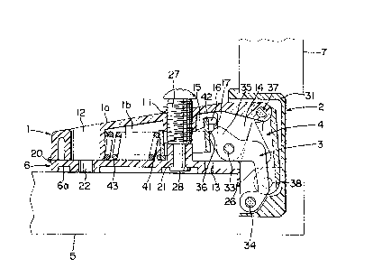
In a hinge of the present invention, a rotor 2 is
connected to a front part of a base 1 by first and second
ratatable link arms 3 and 4 so tha-t the rotor 2 can rotata
with respect to the base, and the base 1 is fitted
to a main bod~ 5 of furniture, or the like, b~ a
fitting member 6 while -the rotor 2 is fitted to a
door 7 of the furniture or the like in such
a manner that it can rotate relatively to
:ILX~75~
-- 3 --
the main body 5.
The base 1 is integrally molded from a syn-thetic resin
and has a subs-tantially box-like shape which is open at its
lower surface. ~ screw hole 11 is defin.ed at a front
center oE an upper shee-t portion la of the base 1, while
a through-hole 12 extendiny i.n a vertical direction i.s
formed at a rear end part of the base 1. Fitting recess
portions 13 are formed at the lower edge portions of both
side shee-t portions 1b of the base 1. ~ s~it portion 1~
is formed at a front par-t of the base 1. Thick portions
15 tha-t project inward are formed a-t the upper parts of
both side sheet portions lb of the base 1. Elongated
holes 16 -that ex-tend in a longitudinal direction are bored
at the upper par-ts of these thic]c portions 15, respectively.
Groove portions 17 are formed on the inner surfaces of the
thick portions 15 in such a manner as to extend upward
from the lower edges of the thick portions and reach the
front parts of -the elongated holes 16, respectivel~.
The fitting member 6 is molded integrally with the
base 1 from a synthe-tic resin. In other words, the base
1 and the fitting member 6 are connected integrally at
their rear end portions by a hinge portion 20 having a
reduced thickness so that they can rota-te
with each other. An engagement hole 21 is
formed on a lower sheet portion 6a of the fitting member
~ ;~751~i5
6 in such a manner as to face the screw hole 11 of -the
base 1, and another through-hole 22 is formed at the rear
of the former in such a manner as to face the through-hole
12 of the base. Both side sheet portions 6b are formed
S on both side of the lower sheet portion 6a of the fi-tting
member 6 and clamp the base I from both sides through fit-
ting edge por-tions 23 in-to which the fit-ting ~ecess portions
13 of the base 1 are fitted. Fitting plate portions 24
are formed to projec-t from the external sides of -these
side sheet portion 6b, respectively, and are equipped
with elongated through-holes 25 that extend to the right
and left. A loca-ting plate portion 26 is formed at the
fron-t end portion of the fitting member 6 and is bent
downward perpendicularly.
A set screw 27 is screwed into the screw hole 11 of
the base 1 and a ring-like engagement portion 28 formed
at the tip of this set screw 27 engages wlth the engage-
ment hole 21 of the fitting member 6. In o-ther words,
the base 1 is supported by, and fixed to, the fit-ting
member 6 by the set screw 27 in cooperation with -the
hinge portion 20 having a reduced thickness that is de-
scribed a~ready.
~he rotor 2 is integrally molded from a synthetic
resin, and has a cap portion 31 having one of the surfaces
thereof open and sheet-like fitting portions 32 that are
~2~5~.~5
-- 5 --
formed to project from bo-th sides of the open surface of
the cap portion 31. The cap portion 31 of.this ro-tor 2
is buried in the door 7 of the furniture or the like and
is fixed thereto by screws through the fitting portions 32.
The first link arm 3 is shaped by a me-tal sheet or
the like in a subs-tantially U-shaped form. ~he base end
portion of the first link arm 3 is rotatably supported
by a shaf-t 33 below and inside the slit portion 14 of the
base 1, while -the -tip of the first link arm 3 is ro-ta-tably
supported by a shaft 34 inside the cap portion 31 of the
rotor 2. An ex-tension portion 35 is formed at the base
end portion o:E the first link arm 3 in swch a manner as
to extend rearward from -the shaft 33, and a cam surface
36 curved in the convex form is formed on the rear surface
of this extension portion 35.
The second link arm 4 is made from a metal sheet
or the like in a substantially U-shaped cross-section.
The base end of the second:link arm :4 is rotatably supported
by a shaft 37 above the front end portion of the base
1, while its tip is supported rotatably by a shaft 38
inside the cap portion 31 of the rotor 2.
Reference numeral 41 represents a frame member which
is made from a metal shee-t or the like in a substan-
tially rectangular shape, and support plate portions
42 are formed to project outward from the upper end
75~S
-- 6
portions on both sicles of its front surface as support
shaft portions, respectively. When engaged with the rear
end por-tions of both elongated holes 16 of the base 1
while encompassing the se-t screw 27 inside the base 1,
the frame member 41 is supported rotatably in a vertical
direction with the support plate por-tions 42 being the
center. The fron-t surface of this frame member 41 is
bought into contact with the cam surface 36 of the first
link arm 3.
A coil spring 43 is interposed between the rear sur-
ace of the frarne member 41 and a front wall of the
through-hole 12 inside the base 1 in order to always urge
forward the frame member 41.
The locating plate portion 26 of the fitting member
6 is engaged wi-th the open edge of the main body 5 of the
furniture or the like and the screws are fitted to the
main body 5 through the through-holes 22, 25 of the ritting
member 6, whereby the base 1 is fitted to the main body
5 of the furniture or the like -through this fitting member
6. The rotor 2 is fitted to the door 7 of -the furniture
or the like.
When the set screw 27 is sui-tably rotated, -the base
1 is ro-tated relative to the fitting member 6 with -the
hinge portion 20 having -the reduced thickness as the center,
so that the angle of the base 1 relative to the fitting
:L~7~ 5
-- 7
member 6 can be adjusted.
When the door 7 of the furni-ture or the like is opened
or closed, the link arms 3, 4 rota-te rela-tive to the base
1 and to the rotor 2, respec-tively, and this rotor 2 is
rotated and opened and closed. When the first link arm
3 is rotated, the frame member 41 that is urged forward
by the spring 43 is somewha-t ro-tated while i-ts front sur-
face is kept in contact with the cam surface 36 of the
first link arnl 3.
When the door 7, that is, the rotor 2, is closed,
the frame member 41 is brought into contact with the portion
near the lower corner of the cam surface 36 of the first
link arm 3 as shown in Fig. 1. At this time, force acts
upon the extension portion 35 of the first link arm 3 in
a direction above the shaft 33 supporting the firs-t link
arm 3 to the base 1, wi-th the contact point between the
cam surface 36 and the frame member 41 beiny the point
of action as shown in the drawing. In other words, the
first link arm 3 is urged in the closing direction and
the ro-tor 2 is kept closed.
When'the,,frame member 41 is assembled to -the base 1,
it is placed into -the base 1 from the lower open surface
of the base 1 and the support pla-te portions 42 of the
frame member 41 are then erlgaged with the elongated holes
16 through -the groove por-tions 17 of the base 1. Since
~ ~7~5S
-- 8 --
there are provided -the groove por-tions 17 whlch the suppor-t
plate portions 42 of :the Erame member 41 pass through,
the frame member 41 can be assembled easily to the base 1.
: On the othe~ :hand, when the ro~or 2.is opened..and
closed, -the con-tact point of -the spring 43 to the frame
member 41 is on the opposi-te side to the suppor-t plate
portion 42 of the frame member 41 with respec-t to the
contact point of -the cam surface 36 of the first link
arm 3 to the frame member 41, so that the spring 43 urges
forward the frame member 41 and at the same time, the
force also acts cowlter-clockwise wi-th the contact poin-t
oE the firs-t link arm 3 to the frame member 41 being the
center. In other words, the support plate portions 42
of the frame member 41 are always urged rearward.
Accordingly~ the support pla-te portion 42 always
stays at the rear part of the elongated hole 16 but does
not move for-th toward the front part of the elongated
hole 16 continuing the groove por-tions.. Namely, although
the groove portions 17 facili-tate the assembly of the
frame 41 as described already, the frame member 41 does
not fall off once it is assembled.
As described already, -the first link arm 3 is urged
by the spring 43 through the frame member 41 and -this
frame member 41 is supported inside the base 1 in such
a manner as to encompass the se-t screw 27. Accordingly,
4~ ~ ty C~ ~'11 t- ~-
the set screw 27 does no-t become an obstacle, and the
~pring 43 can be disposed at.the back:of the.set screw
inside the base 1, so that the space inside the base 1
can be utilized effectively and the base 1 can be made
compact. In o-ther words, the hinge carl be made compac-t
eventually.
Since the base 1 and the fitting member 6 are
integrally formed through the hinge portion 20 having a
reduced thickness, their formir1g and assembly become easy.
Incidentally, the base 1 and the fitting member 6
may be shaped by bending an iron sheet or bhe like, but
if they are molded from the synthe-tic resin as in this
embodiment, they are free from possible rust. If the
base 1 and the fitting member 6:are:shaped by.bending the
iron sheet, the bent portion between the base 1 and the
fitting member 6 (that corresponds to the hinge portion
20 of.the reduced thickness in this embodiment) will be
bent repeatedly -to adjust the angle of the base 1 and
will be broken, or cracks will occur at -the bent portion
at the time of shaping when it is ben-t only once. If the
base 1 and the fitting member 6 are molded integrally
from the synthetic resin, breakage is difficul-t to occur
in the hinge portion 20 of the reduced -thickness tha-t
connec-ts them toge-ther.