Note : Les descriptions sont présentées dans la langue officielle dans laquelle elles ont été soumises.
PHA 21353 1 29.10.1987
Two capacitor apparatus for sequential starting and operation of
~ultiple series connected discharge lamps
BACKGROUND OF THE INVENTION
This invention relates to apparatus for starting and
operating a plurality of electric discharge lamps, such as ~luorescent
lamps or the like. More particularly, the invention is directed to such
apparatus which is more reliable than similar prior art apparatus in
that it prevents burn-out of the ballast transformer windings in the
case of a malfunction of a discharge lamp.
U.S. Patent No. 2,558,293 (A.E. Feinberg, 6/26/51)
describes a ballast apparatus for starting and operating two gas
discharge lamps in series with sequential starting of the lamps. That
ballast comprises a three-winding transformer having a primary windinq
P, a first secondary winding S1 and a second seconday winding S2,
all of the windings being connected serially in the order named with the
secondary windings arranged in ~oltage bucking relationship to one
another. The windings are all mounted on a unitary elongate magnetic
core side by side, with the two secondary windings on opposite sides of
the primary winding. A ~agnetic shunt is provided between the first
(start) winding designated S1 and the primary winding P. The primary
winding P and the first (start) winding 51 are loosely coupled which
provides a Ielatively high leakage reactance. A first discharge lamp is
conDected in series with a capacitor across the series connection of the
primary winding P and the start winding S1. The second lamp is
connected across the series connection of the first (S1) and second
~S2) secondary windings. Figure ~ of the patent shows a variation
thereof and other variations are also possible. In general, one gas
discharge lamp is connected across windings excluding the second
secondary 52 and including at least the first se~ondary S1, and a
second gas discharge lamp is connected across windings which include at
least both of the secondary windings.
In operation, when the primary winding P is energized by
the AC supply ~oltage, a voltage will be produced in both the primary
winding P and the first secondary winding S1 which will be sufficient
to ignite the first gas discharge lamp. As a result, current will flow
PHA 21353 2 29.10.1987
through the start winding S1 and, because of its high leakage
reactance, a voltage will be produced therein of a phase such as to
produce a substantial voltage component additive relative to the voltage
induced in the second secondary windinq S2. Thus, the second gas
discharge lamp will now ignite. With both of the discharge lamps
operating, there will be a series path for the major portion of the
current through the lamps and the second secondary winding S2. The
first secondary winding S1 is effectively bypassed because its high
leakage reactance impedes the flow of current therethrough. Therefore,
the winding S1 can be, and in commerclal versions has been made of a
large number of turns of vexy fine wire since it carries so little
current during operation. The two lamps are ignited in sequence and
thereafter are operated in series from the AC supply voltage via the
secondary winding S2 and the aforesaid capacitor. The resultant
ballast i5 ver~ small and compact, provides high effi~iency and high
power factor operation, and generates very high lamp ignition voltages
with relatively little copper.
Although ballast devices designed in accordance with the
above-described U.S. patent performed success~ully for many years, a
problem occurred after a long period of lamp operation. The second to
start lamp lost emission material from one of its cathodes so that it
then operated as a rectifying tube. In that case a rectified current
flowed in the circuit, essentially a pulsed DC current. This current
could not pass through the series capacitor and consequently was forced
to flow through the start winding S1. The amplitude of current that
flowed in the start winding was much higher than the current for which
this winding was designed. ~ince the start winding was designed to
withstand relatively low currents, it would either heat up excessively
or burn out. The ballast would then have to be replaced at considerable
expense and inconvenience.
In order to solve this problem, Feinberg invented a
ballast apparatus which issued as US Pat. No. 2,682,01~ (6/22/54). This
patent proposed to add a second capacitor C2 connected in series with
the second secondary winding S2 in order to prevent the flow of
rectified (DC) current through the second discharge lamp. This ballast
circuit therefore provided a first capacitor C1 in series with the
first lamp and a second capacitor C2 in series with the second lamp
5~
PHA 21353 3 29.10.1987
(and also in series with the second secondary winding S2). Each of
these capacitors had a capacitance value of approximately twice the
capacitance value of the single series capacitor of the earlier Feinberg
patent (USP 2,55a,293).
S In the event that the second lamp became a rectifier, the
two capacitor ballast circuit was quite effective in preventing the flow
of DC current in each of the lamps since each lamp now had a capacitor
connected in series therewith to block any DC current flow therein. The
flow of rectifying current through the secondary windings also was
blocked, thus protecting the start winding S1 from burn-out. Although
the two capacitor ballast circuit was effective in protecting the
transformer secondary winding (S1) from failure, the resultant
apparatus was too expensive to compete against other commercial ballast
devices. In addition, the two capacitor ballast produced an unacceptable
difference in the current and power between the first and second
discharge lamps. Thus, although the two capacitor ballast avoided the
problems associated with lamp rectification operation, it did not
provide a practical and commercially competitive apparatus.
A further attempt to cure the problems associated with
the one and two capacitor ballast devices described above resulted in a
delta arrangement of three capacitors described in U.S. Pat. No.
3,198,983 (8/3/65), also in the name of A.E. Feinberg. The capacitance
values where then chosen so that the normal operating current still
flowed through each of the lamps and without a material change in the
existing core lamination or the transformer windings. Once again,
although the three-capacitor ballast provided the required ballast
protection, it also was too expensive for widespread commercial use.
In recent years a new form of lamp has come into
widespread use, the so-called energy saver lamp. A characteristic of
this lamp is that it is more susceptible to a loss of cathode emissive
material and therefore to the lamp rectification problem described
above. ~t has been found that in the case of a 60 watt energy saver lamp
the DC current that flows in the event of lamp rectification is greater
than that present with a standard 75 watt lamp. As a consequence, there
have been more ballast failures with energy saver lamps than was
previously experienced with the conventional discharge lamps.
A first attempt to solve the lamp rectification problem
~5~
2010~ 0~
in energy saver lamps utillzed the systems shown ln USP 2,682,014,
but the results were unsatisfactory because the startlng currents
proved to be too low to reliably ignite the lamps. In addition,
there was a considerable lmbalance in the curren~s between the
first and second discharge lamps, which of cour~e is undesirable
from a lighting standpoint and to ~leet the standards required ~or
lamp output.
SUMMARY OF THE INVENTION
The present invention is closely related in operation
and function but ls an improvement over the ballast apparatus
described in U.S. patents 2,558,293 and 2,682,014.
In accordance with a first pra~erred embodiment of the
invention I provide a two capacitor ignition and ballast apparatus
similar to that shown in USP 2,682,014 in which ~wo capacitors are
utilized in series durin~ operation of the lamps, and with only
one capacitor in series with the starting circuit. The second
capacitor is in series with the main windlng (S2). By means of
extensive investigations and tests, I have discovered that
significantly improved results can be obtained by limitiny the
capacitance values of the firs-t and second capacitors C1 and C2
~in series with the ~irs~ and second lamps, respectively~ so that
they do not dif~er from one another by more than 30~, i.e. the
capacitor C2 (in series with the maln operat1ng winding S2) can be
up to 30~ larger than the capacitor C1 in series with the start
winding S1. The range of capacitance values which provide the
improved operation is from C2 - C1 to C2 = 1.3 C1. Attempts to
,~,,
~t7~
2010~-~4~8
use equal value capacitoræ in the apparatus of USP 2,6~2,014
resulted in too great a difference in the current and power
between the first and second lamps.
I have further discovered ~hat the ~wo capacitor
ignition/ballast apparatus exhibits significantly better
characteristics if a slot is provided in the transformer magneti~
core structure under the second secondar~ winding and ln which the
transverse dimqnsion of the slot is in the range of 25-50% of the
core cross~section. In an apparatus designed ln accordance with
USP 2,682,014 it was determined that the transverse width o~ the
slot should be 65% of the core width. In contrast, a slot wldth
of 35% of the core width in an apparatus in accordance with the
present invention provided an apparatus with
4a
~ .
PHA 21353 5 29.10.1987
superior operating characteristics. More particularly, the lamp balance
and capacitor voltages can be adjusted by a proper choice of the slot
width and length.
A further feature of the invention is that the ratio of
the transformer winding turns of winding S1 to the winding S2 is
only approximately 1.53, whereas in ~SP 2,682,014 the turns ratio of the
start winding to the operati.ng winding was about 1.86. In addition, my
invention provides a reduction in the leakage reactance of both the
start winding S1 and the operating winding S2 in comparison with the
apparatus of USP 2,682,014. In fact, the leakage reactance of the start
winding of my improved apparatus does not exceed 4,000 Ohms, and is
approximately 70s of the leakage reactance required to operate the two
lamps in a one capacitor starting and operating apparatus,
Tests on the apparatus in accordance with the invention
revealed a slight but acceptable imbalance of the capacitor voltages,
e.g. 277 volts across one capacitor and 308 volts across the other.
It is therefore an object of the invention to provide an
improved two capacitor apparatus for starting (in seriatim) and
operating a pair of discharge lamps that avoids the drawbacks of, and
provides improved electrical characteristics over, the prior art
apparatus.
Another object of the invention is to provide apparatus
of the character described which prevents the flow of a rectified
current through the transformer secondary windings in the event one of
the discharge lamps operates in a rectifying mode.
A further object of the invention is to provide a t~o
capacitor ballast apparatus in which C1 and C2 are chosen so that
C2 lies in the range of values between C1 and 1.3 C1, and with a
minimum imbalance of the currents and power in the first and second
discharge lamps.
Another object o~ the invention is to provide a two
capacitor ballast apparatus which can satisfactorily ignite and operate
either a pair of instant start lamps or a pair of energy saver lamps
while maintaining a current balance in either pair of lamps.
Further investigation of the problems associated with the
prior art two capacitor ballast apparatus resulted in the discovery that
by connecting the start winding S1 to a tap on the primary winding and
PHA 21353 6 29.10.1987
by the proper choice of the slot dimensions, an improved apparatus was
achieved having good lamp balance, a lower current in the start winding,
a higher open circuit voltage for igniting the second lamp and lower
voltages across the first and second capacitors (C1 and C2). A slot
5 in the core under the transformer secondary winding (S2) having a
transverse slot width approximately 35n~ of the core width provided very
good results. Best results were achieved by limiting the capacitance
value of C2 to a range of values between 1.1 C1 and 1.5 C1. A
further improvement was obtained by reducing the number of turns of the
start winding S1.
It was further discovered that in the case of a 120 volt
ballast, the number of primary winding turns required to start the lamps
is only approximately one-half the turns utilized in a one capacitor
ballast. In fact, with a 120 volt AC supply voltage, only 60 volts of
15 the primary is required to be added to the voltage of the start winding
S1 in order to provide good lamp ignition and operation.
Another interesting discovery was that the ignition
voltage required for starting the second lamp is a function of the ratio
of the two capacitors (C1 and C2). It was found that the open
20 circuit voltage across the second lamp drops appreciably where a large
capacitance ratio of C2 to C1 is used (e.g. 3:1). In contrast, when
C2 was only 30% greater than C1, the open circuit voltage across the
second lamp was appreciable improved. The use of the new slot dimensions
discussed above also contributed to the higher open circuit voltage
25 across the second lamp. The prior art slot ~ith a transverse width of
~5% of the core width was unsatisfactory, whereas a 35% ratio provided
much better ballast characteristics. The prior art slot had a ratio of
transverse length to slot width of approximately 17, whereas the
corresponding slot ratio in accordance with the invention is only about
30 2 . 57 . The open circuit voltagP across the second lamp to start is
reduced as the ratio of the two capacitors approaches unity.
In the embodiment of the invention employing a tapped
primary winding, best results are achieved when the ratio of the second
capacitor (C2) to the first capacitor (C1) lies in the range of 1.1
3S to 1.5. The ignition voltage for the first lamp is provided by the
voltage from the primary tap plus the voltage of the secondary start
winding S1. The path of the two lamps in series includes a portion of
~.~7~
PHA 21353 7 29.10.1987
the primary winding. The voltage of the first-to-start lamp includes a
smaller portion of the primary voltage. The transverse dimension of the
slot under the s~condary winding lies in the range of 25-50% of the
core cross-section.
The invention can also be used with the embodiment shown
in Figure 4 of USP 2,682,014, in which case the path of the two lamps in
series includes the full primary and secondary voltages with the voltage
across the first to start lamp reduced by the tap on the primary
winding.
It is therefore a further object of the invention to
improve the prior art ballast apparatus by connecting the start winding
to an appropriate tap on the primary winding and by providing a modified
slot under the main secondary winding in the magnetic core of the
transformer.
BRIEF DESCRIPTION OF THE DRAWINGS
The objects, advantages and features of the invention
will be better understood by reference to the following detailed
description taken in conjunction with the accompanying drawings in
which:
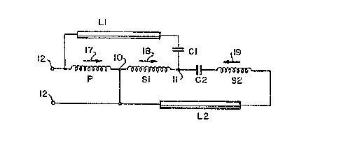
Figure 1 is an electrical circuit diagram of an apparatus
of a first embodiment of the invention,
Figure 2 illustrates the physical layout of the windings
on the magnetic core of the transformer in Figure 1,
Figure 3 is an electxical circuit diagram of a modified
form of the apparatus of Figure 1, and
Figure 4 is an electrical circuit diagram o~ a further
embodiment of the invention.
DESCRIPTION OF THE PREFERRED EMBODIMENTS
Referring now the drawings in which like reference
symbols throughout the several ~igures represents the same or similar
parts, Figure 1 illustrates the basic circuit configuration o~ the
apparatus described in USP 2,~82,014, but modified in accordance with
the present invention 50 as to achieve the improved results and the
objects described above. Figure 2 shows the important details of the
transformer construction in accordance with the invention.
The transformer 20 consists of three windings, a primary
winding P, a first secondary winding S1 tstart winding), and a second
PHA 21353 8 29.10.1987
secondary winding S2 (main operating winding), a:Ll electrically
connected end to end in the order named. These windings are mounted in
windows of a laminated core 21 made of a magnetic material, e.g. iron,
in the manner shown in Figure 2. The primary winding P is mounted on the
magnetic rore be~ween the secondary windings S1 and S2, winding S1
being mounted on the left in Figure 2 and winding 52 on the right. A
magnetic shunt separates the primary winding and the secondary start
winding S1 in the manner disclosed in the above-mentioned U.S. Patents
2,558,293 and 2,682,014.
The magnetic shunt provides the winding S1 with a high
leakage reactance. The main secondary winding S2 is also loosely
coupled to the primary winding P, but more tightly coupled than is the
first (start) winding S1. A small magnetic shynt could also be
provided, if desired, between the primary winding and the second
secondary winding S2 in order to increase the leakage reactance of
winding S2.
The primary winding P and the first secondary winding
S1 are wound in the same direction to provide additive voltages,
whereas the second secondary winding S2 is wound in the opposite
direction to provide a subtractive voltage. The voltage (winding) sense
of the windings relative to one another i5 indicated by the arrows 17,
18 and 13 adjacent the respective windings.
The windings are connected in series with junction points
10 and 11 between windings P and S1 and between windings S1 and
S2, respectively.
A pair of input terminals twelve are adapted to be
connected to a source of low frequency AC supply voltage, for example,
120 V at 60 Hz (not shown). A first discharge lamp L1 is connected in
series circuit with a first capacitor C1 between one of the input
terminals and the junction point 11. A second capacitor C2 is
connected in a series circuit with the main secondary winding S2 and a
second discharge lamp L2 between the junction points 11 and 10. The
lamps L1 and L2 may be fluorescent lamps.
It will be apparent that the first lamp L1 is connected
via capacitor C1 across the primary winding P and the first secondary
winding S1 of the transformer 20. The second lamp L2 is connected
across the first and second secondary windings S1 and S2. Thus, the
~75~
PHA 21353 9 29.10.1987
very loosely coupled secondaxy winding S1 is common to the circuits of
each of the lamps L~ and L2.
Each of the secondary windings has moxe turns than the
primary ~inding so that they step-up the AC supply voltage applied to
the input terminals 12. The first winding 51 has ~ore turns than the
second winding S2. For a detailed description of the manner in which
the lamps are sequentially ignited ~lamp L1 first, lamp L2 second)
and then operated in series, reference l~ay be made to the Feinberg
patents mentioned above. Briefly, when the AC voltage at terminals 12 is
applied to the primary winding P, an additive voltage is induced in the
start winding S1. The resultant of the primary voltage and the voltage
of the start winding S1 appears across the first lamp L1 and is
sufficient to ignite this lamp. Since the voltage induced in the main
winding S2 opposes that induced in the start winding S1, the
resultant voltage across these two windings is initially insufficient to
ignite the second lamp L2.
After ignition of lamp L1, current flows through the
lamp L1 and the first secondary winding S1. In view of the high
leakage reactance of S1, and the presence of capacitor C1, a phase
shift is produced such that the voltage that occurs in winding S1 as a
result of the flo~ of current includes a component that is additive to
the voltage induced in winding S2 by the primary winding P. The
combined effect of the additive voltage component in winding S1 and
the induced voltage in winding 52 is now sufficient to ignite the
2~ second lamp L2 and allow current to flow therein.
With current flowing through both of the lamps, the
relatively high inductive reactance of the start winding S1 serves to
oppose the flow of current therethrough. Thus, in the operating
condition of the lamps, current will flow in a series circuit that
includes the lamps L1 and L2, the capacitors C1 and C2 and the
main secondary winding S2. Since most of the operating current will
bypass the winding S1, it can be made of a fine wire with a large
number of turns. Under normal operatin~ conditions, the apparatus of
Figure 1 will operate in the same way as that of U.S. Patent 2,682,014.
. In the event that one of the cathodes of lamp L2 loses
its emissive material, the lamp will then operate as a rectifier and a
DC current will attempt to flow through this lamp and capacitor ~2 in
~275~
PHA 21353 10 29.10.1987
series therewith. However, the capacitor C2 will prevent this flow of
DC current and thereby prevent the excessive current flow ln winding
S1 thaL caused it to burn out in the one capacitor apparatus of USP
2,558,293.
As discussed above, by limiting the xelative capacitance
values of capacitors C1 and C2 so that ~2 lies in the range of
values from C2 = C1 to C2 = 1.3 C1, the apparatus in accordance
with the invention provides an unexpected improvement in the current
balance between the two lamps. Furthermore, a slot 13 is provided in the
magnetic core 21 under the main secondary winding S2. ~he slot has a
transverse width dimension A of 25-50% ~preferably 35~0) of the core
width dimension B in Figure 2. This particular slot also serves to
improve the lamp current balance, as well as provide other improvements
in the operating characteristics of the apparatus, e.g. a reduction in
capacitor voltage and an increase in the open circuit voltage for lamp
L2 ~
Typical dimensions are a slot width ~ of 0.45" and a core
dimension B of 1.3". In contrast, the prior art apparatus used a slot
width of 0.85" with a core width of 1.3", hence a 65~o ratio of
dimension ~ to ~. Typical values for the capacitor C1 and C2 in
Figure 1 are C1 = 3.0 ~F and C2 in the range of 3.0 yF to 3.9 yF. It
is of course preferable for C1 to equal C2 since this reduces
inventory problems and makes assembly of the apparatus easier.
In the case of a system using energy saver lamps, the
apparatus shown in U.S. Pat. 2~6821014 was unsatisfactory since the
starting currents were too low to reliably ignite the lamps, in addition
to a substantial imbalance of the currents in the two lamps. The
capacitance values for C1 and C2 and the slot dimensions referred to
above solve these problems and produce a satisfactory apparatus for
igniting and operating a pair o~ energy saver lamps.
Figure 3 shows a modified form of the invention shown in
Figure 1. This embodi~ent is similar to ~igure 4 of USP 2,682,014,
except that it is uni~uely modified in accordance with the invention to
provide the various objects and advantages described above and below.
The arrangement of the windings is the same as that described in ~igure
1 except that now the windings are wound to produce the voltage sense
indicated by the arrows 17', 18', and 19' in Figure 3. The voltage in
PHA 21353 11 29.10.19~7
the primary winding P is in the same sense as the voltage in the main
secondary winding S2, whereas the voltage in start winding S1 is
opposed to the voltages in windings P and S2. The lamp L1 is
connected only across the start winding S1 via the capacitor C1. The
lamp L2 is now connected across all three windings. The capacitor C2
is again connected between winding S2 and the junction point 11.
When the AC supply voltage (e.g. 120V, 60Hz) is applied
to input terminals 12, the resultant voltage across all thIee windings
in series is insufficient to ignite lamp L2 since the voltage o~
Ninding S1 is opposed to the voltages across windings P and S2. The
voltage induced in start winding S1 is, however, suf~icient to ignite
lamp L1. Thereafter, due to the relatively high leakage reactance of
winding S1, a voltage is produced across S1 h~ving a component
additive to the voltages of the primary winding P and the secondary
winding S2. The lamp L2 then ignites.
In normal operation, current flows through the lamps L1
and L2 in series. In the event lamp L2 becomes defective and begins
to rectify, the capacitor C2 will again block the flow of a DC current
and thus prevent burnout of the winding S1 in a manner similar to that
described above in connection with Figure 1.
In accordance with the invention, capacitor C2 will be
in the range of capacitance values from C2 = C1 to C2 = 1. 3 C1.
The slot width (A in Figure 2) is again 25-50% of the core width (B in
Figure 2). In addition, further improvement in the apparatus results
when C1 ~ C2 and with the turns of the s~art winding S1 not
exceeding the turns of the main operating winding S2 by more than
40-60%.
~ particularly advantageous arrangement of the invention
utilized capacitors C1 and C2 of approximately 3.35 ~F each, a
primary winding P having ~27 turns, a start winding 51 with 2754 turns
and a main secondary winding S2 of 1792 turns. The AC supply voltage
was 120 V, 60 Hz and the impedance o~ the start winding did not exceed
4000 Ohms. It was also found that there was a reduction in the leakage
reactance of both the start winding S1 and the operating winding S2.
There was a slight variation in the capacitor voltages, with 277 volts
across one capacitor and 30~ ~olts across the other. In contrast, a one
capacitor apparatus usinq a 1.9 ~F capacitor produced a voltage of 575
PHA 21353 12 29.10.1987
volts across the single capacitor.
The turns ratio of winding S1 to winding S2 is
approximately 1.53, whereas in USP 2,682,014 the corresponding turns
ratio was approximately 1.86.
It is of course possible to relocate capacitor C2 so
that it is connected between the junction point 11 and the right end
terminal of start winding S1. In the case of a 277 volt AC supply
voltage, it is advantageous to connect the left hand terminal of lamp
L2 to a tap on the primary winding P instead of to the input terminal
10 12. In this case, the primary winding preferably has 427 turns between
the tap point and junction point 10 and 544 turns between the tap point
and the input terminal 12. The same 427 turns of primary winding are
utilized in the main circuit including lamps ~1 and L2, and an
additional 544 primary turns is used in series with the 427 turns to
accommodate the 277 V supply voltage.
Figure 4 shows a further embodiment of the invention
which i5 a modification of Figure 1 wherein the start winding 51 is
connected to a tap on the primary winding P. A pair of input terminals
12 are provided for connection to a source of AC supply voltage, e.g.
120 V, 60 Hz. The circ~lit connections in ~igure 4 are the sa~e as in
Figure 1 except that now the second-to-start lamp L2 is connected
across windings S1 and S2 and a portion of the primary winding P. In
accordance with the invention, the slot 13 was modified over the prior
art slot (.85`' x .05") so that the dimension A was reduced to 0.45" and
dimension C was changed to 0.225". The centex line of slot 13 was 2.18"
~rom the right hand edge of core 21, and the overall core length
between the left and right edges was 7.144". The transverse slot
dimension A is again approximately 35% of the core width dimension B.
In one embodiment, the primar~l winding contained 223
turns on either side of the tap point, 2654 turns in winding S1 and
1,792 turns in winding S2. The capacitor C2 ranged in value from
C2 = 1 1 C1 to C2 = 1.5 C1. Only 60 V of the 120 V supply
voltage is utilized as an additive to the start winding in order to
provide good results. The ignition voltage for starting the lamp L2 is
a function of the ratio of the capacitors C2 to C1. The open circuit
voltage across lamp L2 is appreciably improved when C2 is 30~0
gxeater than C1~ along with the slot dimensions indicated. The prior
PHA 21353 13 29.10.1987
art ratio of slot dimensions, i.e. transverse length to slot width was
approximately 17, whereas the new ratio was only 2. The ignition voltage
for lamp L1 is provided by the voltage across the secondary winding
S1 plus the tap voltage of the primary winding. The transverse slot
dimension is in the range of 25-50% of the core cross-section.
The apparatus of Figure 4 comprising a tapped primary
winding, modified slot dimensions and a limited range of values for
capacitors C1 and C2 provides significant advantages over the prior
art apparatus, to wit a much better balance of the lamp currents, a
lower abnormal current in the start winding, a hi.gher open circuit
voltage for the second lamp L2 and lower voltages across capacitors
C1 and C2.
While the invention has been described in accordance with
certain preferred embodiments thereof, various modifications and changes
may be effected by those skilled in the art. Accordingly, it is intended
that the appended claims cover all such modifications and changes as
fall within the spirit and scope of the invention.