Sélection de la langue

Search

Sommaire du brevet 1275791 

Énoncé de désistement de responsabilité concernant l'information provenant de tiers

Une partie des informations de ce site Web a été fournie par des sources externes. Le gouvernement du Canada n'assume aucune responsabilité concernant la précision, l'actualité ou la fiabilité des informations fournies par les sources externes. Les utilisateurs qui désirent employer cette information devraient consulter directement la source des informations. Le contenu fourni par les sources externes n'est pas assujetti aux exigences sur les langues officielles, la protection des renseignements personnels et l'accessibilité.

Disponibilité de l'Abrégé et des Revendications

L'apparition de différences dans le texte et l'image des Revendications et de l'Abrégé dépend du moment auquel le document est publié. Les textes des Revendications et de l'Abrégé sont affichés :

  • lorsque la demande peut être examinée par le public;
  • lorsque le brevet est émis (délivrance).
(12) Brevet: (11) CA 1275791
(21) Numéro de la demande: 1275791
(54) Titre français: RALLONGE SUR POIGNEE D'OUTIL ELECTROMECANIQUE
(54) Titre anglais: EXTENSION HANDLE FOR A HANDHELD ELECTRICALLY POWERED TOOL
Statut: Périmé et au-delà du délai pour l’annulation
Données bibliographiques
(51) Classification internationale des brevets (CIB):
  • B26B 27/00 (2006.01)
  • A01G 3/06 (2006.01)
  • B25F 5/02 (2006.01)
(72) Inventeurs :
  • MEYER, BURTON CARPENTER (Etats-Unis d'Amérique)
  • FAUSER, FRITZ (Etats-Unis d'Amérique)
(73) Titulaires :
  • MARVIN GLASS & ASSOCIATES
(71) Demandeurs :
(74) Agent: MACRAE & CO.
(74) Co-agent:
(45) Délivré: 1990-11-06
(22) Date de dépôt: 1987-04-24
Licence disponible: S.O.
Cédé au domaine public: S.O.
(25) Langue des documents déposés: Anglais

Traité de coopération en matière de brevets (PCT): Non

(30) Données de priorité de la demande:
Numéro de la demande Pays / territoire Date
892,297 (Etats-Unis d'Amérique) 1986-08-04

Abrégés

Abrégé anglais


ABSTRACT OF THE DISCLOSURE
An extension handle (10) facilitating use of a
handheld electrically driven grass shear (12) from an
upright standing position that removably attaches to the
hand grippable portion (14) of the grass shear by depending
pairs of opposed, resilient, inwardly biased clamps (34). A
flexible strip (36) extends through the extension handle for
remote control of the grass shear on/off controls (16, 18)
from the hand gripped section (26) of the extension handle.
The flexible strip includes a depending cam (44) for
laterally moving an on/off slide lock switch (18). Inwardly
directed guide posts (42) within the extension handle direct
movement of the flexible strip substantially in the
direction necessary to actuate the controls on the grass
shear.

Revendications

Note : Les revendications sont présentées dans la langue officielle dans laquelle elles ont été soumises.


THE EMBODIMENTS OF THE INVENTION IN WHICH AN EXCLUSIVE PROPERTY
OR PRIVILEGE IS CLAIMED ARE DEFINED AS FOLLOWS:
1. An extension handle for an electrically powered,
handheld tool having a hand grippable portion, a back to front
slidable, thumb actuatable on/off switch and a laterally
movable switch lock, comprising:
a section attachable to the hand grippable portion of
the tool and a spaced apart hand grippable section connected
by a generally transverse section;
means depending from the attachable section for
clamping over the hand grippable portion of the tool;
means actuatable from the hand grippable section and
extending to the hand grippable portion of the tool for
controlling the on/off switch on the hand grippable portion of
the tool; and a cam carried by the control means for sliding
the switch lock laterally.
2. The extension handle of Claim 1 in which the
clamping means permits removable attachment of the extension
handle.
3. The extension handle of Claim 1 in which the
extension handle is generally hollow and the control means
includes a member that extends through the extension handle
from the hand grippable section to the attachable section.

4. The extension handle of Claim 1 in which the
control means includes an elongated flexible member that
transmits motion from the hand grip section of the extension
handle to the on/off switch of the tool.
5. The extension handle of Claim 4 in which:
the extension handle is generally hollow; and
the flexible member is generally contained within
the hollow extension handle.
6. The extension handle of Claim 5 in which:
there are a number of inwardly projecting guide
posts within the hollow extension handle; and
each of the guide posts has a slot through which
the flexible member passes.
7. The extension handle of Claim 6 in which the
extension handle has a generally elongated "C" shape.
8. The extension handle of Claim 1 in which the
clamping means includes a pair of resilient tabs depending
from the attachable section, the tabs being inherently
biased toward each other.
-6-

9. The extension handle of Claim 8 in which the hand
grippable portion of the tool has a predetermined cross section
and the tabs have inside surfaces which generally conform to
the predetermined cross section.
10. The extension handle of Claim 1 in which the
extension handle has a generally elongated "C" shape.
11. The extension handle of Claim 10 in which the
control means includes an elongated flexible member that
transmits motion from the hand grip section of the extension
handle to the on/off switch of the tool.
12. The extension handle of Claim 11 in which:
the extension handle is generally hollow; and
the flexible member is generally contained within
the hollow extension handle.

Description

Note : Les descriptions sont présentées dans la langue officielle dans laquelle elles ont été soumises.

lZ7S~9~I
BACKGROUND OF THE INVENTION
Field of the Invention
This invention relates generally to an extension
handle for an electrically powered, handheld tool having a hand
grippable portion, a back to front slidable, thumb actuatable
on/off switch and a laterally movable switch lock, comprising:
a section attachable to the hand portion of the tool
and a spaced apart hand grippable section connected by a
generally transverse section;
means depending from the attachable section for
clamping over the hand grippable portion of the tool;
means actuatable from the hand grippable section and
extending to the hand grippable portion of the tool for
controlling the on/off switch on the hand grippable portion of
the tool; and a cam carried by the control means for sliding
the switch lock laterally~
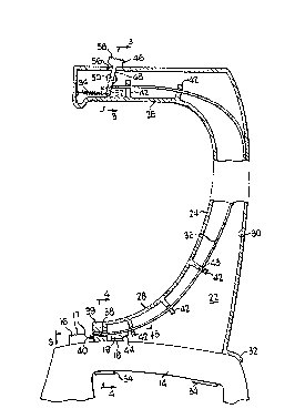
By way of example in the drawings:
FIG. 1 is a perspective view of an extension handle
embodying the present invention attached to a grass shear;
FIG. 2 .is an enlarged sectional view taken generally
along line 2-2 of FIG. l;
FIG. 3 is an enlarged sectional view taken generally
along line 3-3 of FIG. 2;
~IG. 4 is an enlarged sectional view taken generally
along line 4-~ of FIG. 2; and
FIG. 5 is an enlarged sectional view taken generally
along line 5-5 of FIG. 2.
Referring now to the drawings in which like paLts are
designated by like reference numerals throughout the several
views, FIG. 1 shows an extension handle 10 attached
, .
A

1 ~757~
to a battery operated grass shear 12 such as that disclosed
in Edgell, United States Patent 3,623~223. Forward of the
hand grip portion 14, grass shear 12 has an on/off switch
button 16 with serrations 17 to improve the purchase of the
user's thumb on switch 16. The switch is normally biased
rearwardly and must be pushed forward to turn on the grass
shear. As a safety measure, the grass shear is provided
with a biased, laterally slidable switch lock 18 that has an
upstanding part 19 along one side. With the user's hand
properly in place along hand grip portion 14, the side of
the user's thumb displaces switch lock 18 to one side, thus
freeing switch 16 to be pushed forwardly.
Extension handle 10 may be formed as a generally
hollow, elongated "C" of molded halves 21 and 22 of a
relatively rigid plastic. The length of the generally
vertical section 24 of the elongated "C" is approximately
thirty inches to facilitate use of the grass shear from an
upright standing position. Forward of, and generally
transverse to, vertical section 24 is an upper, hand grip
section 26. Also forward of vertical section 24 and
generally parallel to hand grip section 26, is a lower
section 28 that is attachable to the grass shear hand grip
portion 14. The "C" shape of the extension handle positions
the grass shear more directly below the user's hand to
reduce fatigue.
Lower section 28 of the extension handle is open
at the bottom and, together with vertical section 24 and
hand grip section 26, forms a continuous internal conduit
30. Projecting rearwardly and downwardly from the lowermost
--2--

12'~'S79:1
back portion of the extension handle is a flange 32 that
fits the downwardly curving, upper rear corner of the grass
shear hand grip portion 14. Adjacent the front and rear of
each side of lower portion 28 are spaced apart pairs of
clamps 34. As is best shown in FIG. 4, clamps 34 are shaped
to conform to the sides of the hand grip portion of the
grass shear. Clamps 34 are sufficiently resilient to permit
each laterally opposed pair to be forced apart to fit over
the hand grip portion 14 and then be inherently biased back
toward each other to secure extension handle 10 to grass
shear 12.
Extending throughout substantially the entire
length of internal conduit 30 is a flexible strip of plastic
36. The lower end of strip 36 projects out through an
opening 38 in a forward wall 39 of the lower section 28 and
terminates in a downwardly directed tab 40. The height of
opening 38 is just slightly greater than the thickness of
strip 36 so as to restrain vertical movement of the strip
while permitting the strip to slide in and out of internal
conduit 30. Also restraining movement of strip 36 in other
directions, while facilitating movement along the length of
internal conduit 30, are a series of spaced apart guide
posts 42 each having a slot 43 through which the flexible
strip passes. Downwardly turned tab ~0 engages switch 16 to
push the switch forwardly against its bias to turn the grass
shear on in response to outward movement of flexible strip
36. Inboard of tab 40, a cam 44 projects downwardly from
flexible strip 36. Cam 44 engages the upstanding part 19 of

i.Z~57~
switch lock 18 to slide the switch slot laterally in the
direction of the arrow shown in FIG. 5 in response to
outward movement of flexible strip 36.
At the upper end of extension handle 10, flexible
strip 36 is connected to a pivot switch 46. The switch
includes a lever 48 mounted for pivotal movement about a pin
50 received in integrally formed sockets 51 within hand grip
section 26. Below the pivotal connection, lever 48 extends
through an opening 52 in the flexible strip and is biased by
a coil spring 54 towards the front of hand grip section 26.
Above the pivotal connection, lever 48 extends through an
opening 56 and terminates in a serrated thumb actuator 58.
When the user grips section 26 and urges switch 46 forwardly
by thumb pressure upon actuator 58, flexible strip 36 is
pushed rearwardly along the part of internal conduit 30
lying within hand grip section 26, then downwardly along
that part of the conduit formed by the vertical section 24
and finally forwardly through and out of lower attachment
section 28.

Dessin représentatif
Une figure unique qui représente un dessin illustrant l'invention.
États administratifs

2024-08-01 : Dans le cadre de la transition vers les Brevets de nouvelle génération (BNG), la base de données sur les brevets canadiens (BDBC) contient désormais un Historique d'événement plus détaillé, qui reproduit le Journal des événements de notre nouvelle solution interne.

Veuillez noter que les événements débutant par « Inactive : » se réfèrent à des événements qui ne sont plus utilisés dans notre nouvelle solution interne.

Pour une meilleure compréhension de l'état de la demande ou brevet qui figure sur cette page, la rubrique Mise en garde , et les descriptions de Brevet , Historique d'événement , Taxes périodiques et Historique des paiements devraient être consultées.

Historique d'événement

Description Date
Inactive : CIB de MCD 2006-03-11
Le délai pour l'annulation est expiré 1999-11-08
Lettre envoyée 1998-11-06
Accordé par délivrance 1990-11-06

Historique d'abandonnement

Il n'y a pas d'historique d'abandonnement

Historique des taxes

Type de taxes Anniversaire Échéance Date payée
TM (catégorie 1, 7e anniv.) - générale 1997-11-06 1997-10-31
Titulaires au dossier

Les titulaires actuels et antérieures au dossier sont affichés en ordre alphabétique.

Titulaires actuels au dossier
MARVIN GLASS & ASSOCIATES
Titulaires antérieures au dossier
BURTON CARPENTER MEYER
FRITZ FAUSER
Les propriétaires antérieurs qui ne figurent pas dans la liste des « Propriétaires au dossier » apparaîtront dans d'autres documents au dossier.
Documents

Pour visionner les fichiers sélectionnés, entrer le code reCAPTCHA :


Pour visualiser une image, cliquer sur un lien dans la colonne description du document. Pour télécharger l'image (les images), cliquer l'une ou plusieurs cases à cocher dans la première colonne et ensuite cliquer sur le bouton "Télécharger sélection en format PDF (archive Zip)" ou le bouton "Télécharger sélection (en un fichier PDF fusionné)".

Liste des documents de brevet publiés et non publiés sur la BDBC .

Si vous avez des difficultés à accéder au contenu, veuillez communiquer avec le Centre de services à la clientèle au 1-866-997-1936, ou envoyer un courriel au Centre de service à la clientèle de l'OPIC.


Description du
Document 
Date
(aaaa-mm-jj) 
Nombre de pages   Taille de l'image (Ko) 
Page couverture 1993-10-13 1 11
Revendications 1993-10-13 3 65
Abrégé 1993-10-13 1 18
Dessins 1993-10-13 1 28
Description 1993-10-13 4 123
Dessin représentatif 2001-04-17 1 10
Avis concernant la taxe de maintien 1998-12-07 1 177
Taxes 1996-11-06 1 39
Taxes 1995-10-05 1 51
Taxes 1994-08-15 1 55
Taxes 1993-09-08 1 30
Taxes 1992-09-17 1 24