Sélection de la langue

Search

Sommaire du brevet 1275938 

Énoncé de désistement de responsabilité concernant l'information provenant de tiers

Une partie des informations de ce site Web a été fournie par des sources externes. Le gouvernement du Canada n'assume aucune responsabilité concernant la précision, l'actualité ou la fiabilité des informations fournies par les sources externes. Les utilisateurs qui désirent employer cette information devraient consulter directement la source des informations. Le contenu fourni par les sources externes n'est pas assujetti aux exigences sur les langues officielles, la protection des renseignements personnels et l'accessibilité.

Disponibilité de l'Abrégé et des Revendications

L'apparition de différences dans le texte et l'image des Revendications et de l'Abrégé dépend du moment auquel le document est publié. Les textes des Revendications et de l'Abrégé sont affichés :

  • lorsque la demande peut être examinée par le public;
  • lorsque le brevet est émis (délivrance).
(12) Brevet: (11) CA 1275938
(21) Numéro de la demande: 1275938
(54) Titre français: APPUI DU BORD DE FUITE D'UNE AUBE D'ETAGE REGULATEUR SUR TURBINE A VAPEUR
(54) Titre anglais: TRAILING EDGE SUPPORT FOR CONTROL STAGE STEAM TURBINE BLADE
Statut: Périmé et au-delà du délai pour l’annulation
Données bibliographiques
(51) Classification internationale des brevets (CIB):
  • F01D 05/30 (2006.01)
  • F01D 05/14 (2006.01)
(72) Inventeurs :
  • HANCOCK, BYNUM V. (Etats-Unis d'Amérique)
(73) Titulaires :
  • WESTINGHOUSE ELECTRIC CORPORATION
(71) Demandeurs :
  • WESTINGHOUSE ELECTRIC CORPORATION (Etats-Unis d'Amérique)
(74) Agent: SMART & BIGGAR LP
(74) Co-agent:
(45) Délivré: 1990-11-06
(22) Date de dépôt: 1987-07-17
Licence disponible: S.O.
Cédé au domaine public: S.O.
(25) Langue des documents déposés: Anglais

Traité de coopération en matière de brevets (PCT): Non

(30) Données de priorité de la demande:
Numéro de la demande Pays / territoire Date
897,672 (Etats-Unis d'Amérique) 1986-08-18

Abrégés

Abrégé anglais


ABSTRACT OF THE DISCLOSURE
A side entry rotatable control stage blade with a
wedge shape trailing edge support on the root portion which
is formed to have two generally right trapezoidal surfaces
which converge and a notch disposed on the opposite side of
the platform with a trapezoidal surface which registers
with one of the trapezoidal surfaces on the trailing edge
support of the adjacent blade when the blades are disposed
in a circular array in a steam turbine.

Revendications

Note : Les revendications sont présentées dans la langue officielle dans laquelle elles ont été soumises.


What is claimed is:
1. A rotatable blade for a steam turbine
comprising:
a root portion;
a root platform portion disposed radially out-
wardly with respect to the root portion;
an airfoil portion extending radially outwardly
from the root platform portion and having a leading and a
trailing edge;
said root platform portion having an extension which
supports the trailing edge of the airfoil portion;
said extension being wedge shaped and having two
generally right trapezoidal surfaces and two triangular
shaped sides; and
said root platform having a notch with a generally
right trapezoidal surface which receives and supports the
wedge shaped extension of the adjacent blade when the
blades are disposed in a circular array on a steam turbine.
2. A rotatable blade as set forth in claim 1 and
further comprising a shroud platform portion disposed
radially outwardly from the airfoil portion.
3. A rotatable blade as set forth in claim 2,
wherein the shroud platform portion has a shroud extension
which supports the trailing edge of the airfoil portion.
4. A rotatable blade as set forth in claim 3,
wherein the shroud platform portion has a notch for receiv-
ing the shroud extension of the adjacent blade when the
blades are disposed in a circular array in the turbine.

5. A rotatable blade as set forth in claim 4,
wherein the shroud platform portion has a tenon extending
radially outwardly therefrom.
6. A rotatable blade as set forth in claim 5,
wherein the tenon has a circular cross section and is
utilized to attach a shroud ring which joins the blade in
groups when the blades are disposed in a circular array in
a steam turbine.
7. A rotatable blade as set forth in claim 6,
wherein the root portion has a generally Christmas tree
shaped cross section.
8. A rotatable blade as set forth in claim 7,
wherein the thickness of the root platform decreases from
the leading to the trailing end of the airfoil portion.
9. A rotatable blade as set forth in claim 8,
wherein the thickness of the shroud platform portion
decreases in thickness from the leading to the trailing end
of the airfoil portion.
10. A rotatable blade as set forth in claim 9,
wherein the distance between the root platform portion and
the shroud platform portion increases from the leading to
the trailing edge of the airfoil portion.
11. A rotatable blade for a steam turbine
comprising:
a root portion;
a root platform portion disposed radially out-
wardly with respect to the root portion;
an airfoil portion extending radially outwardly
from the root platform portion and having a leading and a
trailing edge,
said root platform portion having an extension which
supports the trailing edge of the airfoil portion;
said extension being wedge shaped and having two
generally rectangular surfaces and two triangular shaped
sides; and
said root platform having a notch with generally
rectangular surface which receives and supports the wedge

shaped extension of the adjacent blade when the blades are
disposed in a circular array on a steam turbine.
12. A rotatable blade as set forth in claim 11
and further comprising a shroud platform portion disposed
radially outwardly from the airfoil portion.
13. A rotatable blade as set forth in claim 12,
wherein the shroud platform portion has a shroud extension
which supports the trailing edge of the airfoil portion.
14. A rotatable blade as set forth in claim 13,
wherein the shroud platform portion has a notch for receiv-
ing the shroud extension of the adjacent blade when the
blades are disposed in a circular array in the turbine.
15. A rotatable blade as set forth in claim 14,
wherein the shroud platform portion has a tenon extending
radially outwardly therefrom.
16. A rotatable blade as set forth in claim 15,
wherein the tenon has a circular cross section and is
utilized to attach a shroud ring which joins the blade in
groups when the blades are disposed in a circular array in
steam turbine.
17. A rotatable blade as set forth in claim 16,
wherein the root portion has a generally Christmas tree
shaped cross section.
18. A rotatable blade as set forth in claim 17,
wherein the thickness of the root platform is generally
constant from the leading to the trailing end of the
airfoil portion.

Description

Note : Les descriptions sont présentées dans la langue officielle dans laquelle elles ont été soumises.

~2~ 3~3
TRAILING EDGE SUPPORT FOR CONTROL
STAGE STEAM TURBINE BLADE
BACKGROUND OF THE INVENTION
This invention relates to steam turbine blades
and more particularly to supports for the trailing end of
the airfoil of the control stage blades.
5As shown in Figures 1 through 4, platform por-
tions of the blades herebefore made have a pyramid shaped
extension for supporting the trailing edge of the airfoil.
The pyramid shaped portions are formed to optimize the
stress distribution, hut the angular s~des require compli-
lQ cating machining operations and are difficult to check for
dimensional accuracy.
SUMMARY OF TEE INVENTION
In gen~ral, a rotatable blade for a steam tur-
b~ne, whe~ made in accordance with this invention, compris-
es a root portion, a r~ot platform portion disposedradially outwardly with respect to the root portion, an
airfoil portion extendiny radially outwardly from the root
platform portion. The airfoil portion has a leading edge
and a trailing edge. The platform portion has an ~xten-
sio~, which suppor~s the trailing edge o~ t~e airfoilportion. The extension is wedge shaped and has two gener~
ally right trapezoidal sides and two triangular sides. The
root platform portion also has a notch with a generally
right trapezoidal surace, which receives and supports the
wedge shaped ext~nsion o the adjacent blade when the
blades are disposed in a circular array in a steam turbine.
"t~
P`':I ~`'tl

~2~3~ -
BRIEF DESCRIPTION OF THE DRAWINGS
The objects a~d advantages of this invention will
become more apparent by reading the following detailed
description in conjunction with the accompanying drawings,
in which:
Figure 1 is an, elevational view of a prior art
turbine blade;
Figure ~ is a plan view of the prior ar~ blade;
Figure 3 is an enlarged partial isometric view
showing a pyremid platform extension for a prior art blade;
Figure 4 is an enlarged partial isomQtric view
showing a notch in the platform of a prior art blade;
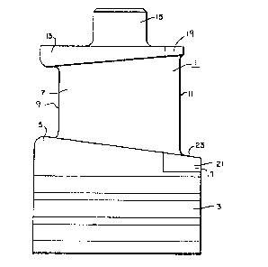
Figure 5 is an elevational ~Jiew of a steam
turbine blade made in accordance with this invention;
Figure 6 is a plan view of the blade;
Figure 7 is an enlarged partial isometric view
showing the extension of the platform of the blade;
Figure 8 is an enlarged partial isometr'ic view
showing a notch in the blade.
Figure 9 is an enlarged partial isometric view
showin~ an alternative e~.ension and platform of the blade;
and
, Figure 10 is an enlarged partial isometric view
- showing an alternative notch and platform of the blade.
ESCRIPTION OF TXE PREFERRED EMBODIMENT
Referring now to the drawings in detail, like
reference numerals refer to similar parts in all of the
figures. A rotatable side entry blade 1 for the control
stage of a steam turbine is shown in Eigures 5 and 6. The
blade 1 comprises a Christmas tree shaped root portion 3,
which fits into a Christmas tree shaped groove in a turbine
~otor (not shown). Extending radially outwardly ~rom the
root portion 3 is a root platform portion 5, an airf~il
portion 7 with a leading and trailing edge 9 and 11,
respectively, a shroud platform portion 13, and a tenon 15
having a circular cross section for attaching a shroud
segment (not shown) which joins the blades in ~roups when

they are installed in a circular array in a turbine rotor
(not shown). As shown in Figure 5, the platfor~ portions 5
and 13 decrease in thickness from the leading edge 9 to the
tailing edge 11 of the hlade 1.
The trailing edge 11 of the airfoil 7 extends
beyond the generally rectangular portion of the platforms 5
and 13 so that an extension 1~ on the root platform portion
5 and an extension 19 on the shroud platform portion 13 are
provided to support the trailing edgc of the blade 1. The
1~ extension 17 on the root platform portion 5 is wedge shaped
and is formed to have two right trapezoidal surfaces 21 and
23 which converge and two triangular surfaces 25 and 27 on
opposite sides of the we~ge sha~ed extension 17. The right
trapezoidal surfaces ~ and ~4 are formed to have a right
angle where the extension 17 joins the root platform
portion 5. Blades la herebefore made had generally quadri-
lateral surfaces as shown in Figures 1 and 4 with the
inboard side of the quadrilateral forming an acute angle
generally parallel to the traiLing end 11 of the airfoil
portion 7. This optimized the stresses in the extension
17a. The wedge shaped extension 17 as shown in Figures 5
and 7 formed with trapezoidal surfaces has some adverse
stress concentrations, but is easier to manufacture, check
the dimensio~al accuracy and eliminates the need for
specially designed cutting tools.
On the opposite side of the root platform 5 is a
notch 29 which also has a right trapezoidal surface 31,
which registers with the right trapezoidal surface 21 on
the extension 17 of the adjacent blade when the blades are
assembled in a circular array in a turbine.
The extension 19 on the shroud platform 13 is
generally rectangular shaped rather than trapezoidally
shaped as shown in the prior art and a rectangular shaped
notch 33 is disposed on the opposite side of the shroud
platform 33 which registers with, or fits, the extension 19
; of the adjacent blade, when th~ blades are disposed in a
circular array in a steam turbine.

Figure 9 shows another embodiment in which an
extension 17b extends from the root platform /~ ~nd an
extension l9b extends from the shroud platform ~. The
extension 17b is formed to have two rectangular surfaces
21b and 23b which converge and two triangular surfaces 25b
and 27b on opposite~sides o~fb the wedge-shaped extension
17b. The surfaces 2~ and ~b are rectangular because the
root platform 5b is generally a constant thickness. Figure
10 shows a notch 29b in the root platform 5b which has a
rectangular surface 31b. The notch 29b registers with the
extension l9b on the adjacent blade when the blades are
disposed in a circular array in a rotvr of a steam turbine.
The extensions 17 and 19 for supporting ths
trailing edge 11 of the airfoil portion 7 of the blade
lS while resulting in some adverse stresses advantageously
make the blades easier to manufacture and measure the
dimensional accuracy of the particular elements, eliminate
specially designed cutters and allow simple clearance
checks upon assembly of the blades in a circular array.
The angular cut herebefore utilized necessitated measure-
ments over a roll pin and generating a compound angle on
the trailing edge support and in the notch in the plaLform,
both OI which ars difficult to machine.

Dessin représentatif
Une figure unique qui représente un dessin illustrant l'invention.
États administratifs

2024-08-01 : Dans le cadre de la transition vers les Brevets de nouvelle génération (BNG), la base de données sur les brevets canadiens (BDBC) contient désormais un Historique d'événement plus détaillé, qui reproduit le Journal des événements de notre nouvelle solution interne.

Veuillez noter que les événements débutant par « Inactive : » se réfèrent à des événements qui ne sont plus utilisés dans notre nouvelle solution interne.

Pour une meilleure compréhension de l'état de la demande ou brevet qui figure sur cette page, la rubrique Mise en garde , et les descriptions de Brevet , Historique d'événement , Taxes périodiques et Historique des paiements devraient être consultées.

Historique d'événement

Description Date
Inactive : CIB de MCD 2006-03-11
Inactive : Demande ad hoc documentée 1994-11-06
Le délai pour l'annulation est expiré 1994-05-07
Lettre envoyée 1993-11-08
Accordé par délivrance 1990-11-06

Historique d'abandonnement

Il n'y a pas d'historique d'abandonnement

Titulaires au dossier

Les titulaires actuels et antérieures au dossier sont affichés en ordre alphabétique.

Titulaires actuels au dossier
WESTINGHOUSE ELECTRIC CORPORATION
Titulaires antérieures au dossier
BYNUM V. HANCOCK
Les propriétaires antérieurs qui ne figurent pas dans la liste des « Propriétaires au dossier » apparaîtront dans d'autres documents au dossier.
Documents

Pour visionner les fichiers sélectionnés, entrer le code reCAPTCHA :


Pour visualiser une image, cliquer sur un lien dans la colonne description du document. Pour télécharger l'image (les images), cliquer l'une ou plusieurs cases à cocher dans la première colonne et ensuite cliquer sur le bouton "Télécharger sélection en format PDF (archive Zip)" ou le bouton "Télécharger sélection (en un fichier PDF fusionné)".

Liste des documents de brevet publiés et non publiés sur la BDBC .

Si vous avez des difficultés à accéder au contenu, veuillez communiquer avec le Centre de services à la clientèle au 1-866-997-1936, ou envoyer un courriel au Centre de service à la clientèle de l'OPIC.


Description du
Document 
Date
(aaaa-mm-jj) 
Nombre de pages   Taille de l'image (Ko) 
Dessins 1993-10-12 5 115
Revendications 1993-10-12 3 107
Abrégé 1993-10-12 1 13
Description 1993-10-12 4 165
Dessin représentatif 2001-10-30 1 9
Taxes 1992-09-21 1 109