Note : Les descriptions sont présentées dans la langue officielle dans laquelle elles ont été soumises.
-- ~,Z~6~g~
Title: ADJUSTABLE DOUBLE-ACTING DAMPER
Inventor: Benjalnin r. Ilough~on
BACK~ROUND OF T}IE INVENTION
This invention relates~ generally, to devices for damping
or cushioning ~he movement between two objects moving relative
to one another, and relates more particu1arly ~o a new and
improved dashpot type of damper.
The type of damper with which this invention is concerned
commonly includes a housing assembly defining an elongated
cavity for containing hydraulic fluid and a piston assembly
having a head received by the elongated cavity ~or sliding
movement in either of two directions therealong. The housing
assembly is connectable to one of two objects movahle toward or
away ~rom one another, and the piston assembly is connectable
to the other of the two objects. The piston head is arranged
in the elongated cavity so as to separate the cavity into two
varia~le-volume chamhers, and the housing assemhly includes a
network of hydraulic fluid flow passages in flow communication
with the first and second chambers. As the two objects move
toward~one ano~her, the pis~on moves in one direction relative
~o and along the cavity to force hydraulic fluid through the
flow passages from one of~the variable-volume chambers to the
other. Sim~ilarly, as the two objects move away from one
,, . ~
.- .
- ' , - ': , ,
.. : . -:: , `
' ': : ~ : : . '
.~7~
2-
another9 the piston moves in the other direc~ion relative ~o
and along the cavity to force hydraulic Fluid through the flow
passages from said other of the varia~lc-volume cham~ers to
said one chamber. For purposes of adjllsting the darnping or
cushioning ef~ect of a damper of the aforesaid descrihed Iype,
the damper includes adjustment mechanisrns for varying the size
or configuration o~ its flow passages to thereby vary the flow
characteristics of hydraulic fluid moving hetween the two
variahle-volume chambers.
In the past, damper selection required extensive
engineering time to determine the proper parmeters under which
a damper could best be utilized, with extensive testing,
modification and re-testing. Accordingly, it would he highly
desirable to provide a damper which suhstantially reduces
complex motion analysis hy allowing the user to determine an
optimum setting, and then lock the damper in that position with
a plug-in type self-contained unit, the unit allowing damping
to he programmed or pre-determined for tension, compression or
both, and the unit enabling the damper to he adjustable in
compression and free-flow in tension or adjustable in tension
and flec Elow in Fompression or hoth.
:
.,
.. . . :
. - .
.. . : . .
- . - - : .
.
.
.. . ~. .. .
~. .. ' ~''', ' ' ' :
~-,. . ~ '
~276~
-3-
SUMMARY OF TIIE lNVrNIION
An object of the presenl inven-t;on is to provide a new and
improved dashpot type damper.
Another object of the presen~ invention is to provide such
a damper having improved means for controiling the damping
effect of the damper.
Still another object is to provide such a damper wherein
the cushioning of movement ~etween two objects toward and away
from one another can be independently con~rolled.
Yet still another object of the presen~ invention is to
provide such a damper having damping-adjustment means which are
easily accessib]e.
I~ is a more parlicular ohject of the present invention to
provide such a damper ~hich al]ows the user to determine an
optimum setting and then lock the darnper in that setting with a
readily accessihle, plug-in type sel~-concained unit which
allows the damping to he programmed or pre-determined for
tension, compression or both.
It is a more particular object of the present invention to
provide such a damper having a readily accessihle, plug-in type
self-contained unit which enahles the damper to be adjustable
in compression and free-flow in tension or adjustahle in
t~nilon and [ree-Elow in compression or hoth.
- . : : . .
., , ~ . . ~ , .. . .
- . .. . , - :, . :, . .
,, : ~ . . . .
. . . . . . . .
, , -:
~631 ~
A further o~ject oE the present invention is ~o provide
such a damper which is economical to manlJ~acture and effective
in operation.
This invention resides in a new and improved damper for
acting between ~wo objects subject to relative movement, for
example toward and away from one ano~her.
The damper comprises piston means, hol~sing means and
hydraulic fluid flow control means. The piston means includes
a head and a rod connected to the head for securement one of
the two objects. The housing includes means for securemen~ to
the other of the two objects and includes means de~ining an
elongated cavity for containing hydraulic fluid. The piston
head is received by the elongated cavity so as to separate the
cavity into ~irst and second cham~er and is adapted to s]i~ahly
move relative to and along the elongated cavity and thereby
vary the volumes of the ~irst and second chambers as the in
response to relative movement between the two ohjects connected
to the housing means and piston means. The housing further
includes means deEining an access opening, a first passage, and
a second passage wherein the first chamber communica~es with
the access opening through the ~irst passage and the second
chamber communicates with the access opening through the second
passage. The hydraulic fluid control means includes a l)ody
sealingly accepted hy the access opening and defines a
.
.. : . :.
,,, ~ .,
- .
.- , . . .- . ............................. :
-: . : -
~ . -: , . , '
~ Z7~
5-
passageway through the bocly providing flow communication
between the first and second passages and there~y providing a
flow path for hydraulic fluid ~orced to exi~ one of the first
and second chambers as the volumes of the chambers are varied
by the relative movement of the two objects. The flow control
means further includes means associated with the de~ined
~assageway for controlling or metering the flow of hydraulic
~uid in one direction therethrough so that as hydraulic fluid
is forced to flow through the passageway in said one direction,
the damping effec~ of the damper is controlled.
In accordance with this invention, the flow control means
is a self-contained unit or cartridge which can be easily
separated or detached from the remainder of the damper. Such
features permit the flow control means to be clea~ed, repaired
or modified with no disassembly o~ the remainder o~ the
damper. Furthermore, such features accommodate the replacement
of one flow control means which provides preselected fluid flow
characteristics with another flow control means which provide
alternative fluid flow characteristics. Still further, since
the flow control means effectively define a conduit portion of
the flow path Eor hydraulic fluid moving between Ihe first and
second chambers. the defined conduit portion can be removed and
altered to vary or adjust the damping effect of the damper.
In anotber aspect of this invention, the flow control means
is a first flow control means for controlling hydraulic fluid
.. . . - , ~ .
-6
flow in one direction between ~he first and second chamher, ~h~
housing includes means defining a second access opening
urranged in flow communication wi~h the passageway o~ the first
control means, with the first passage and with the second
passage, and the damper further includes a second hydraulic
fluid flow conlrol means for controlling hydraulic ~luid flow
in the direction between the ~irst and second cha~ber opposite
said one direction. Because the first and second control means
are independent from one another, ~he darnping ef~ects of the
damper as two objects move toward one another and as the tow
ob~ects move away from one another can be independently
controlled in tension and compression.
Other objects and advantages of this invention will becomc
apparent upon reading ~he ensuing description with reference to
the accompanying drawings.
BRIEF DESCRIPTION OF T~ RAWINGS
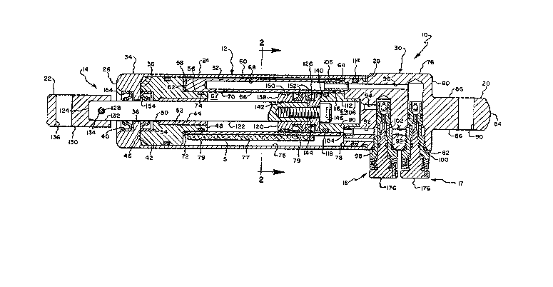
Fig. 1 is a longitudina~ cross-sectional view o~ a damper
constructed in accordance with this invention.
Pig. 2 îs a cross-sectional view taken about on lines 2-2
o~ Fig l;
Fig. 3 is a longitudinal cross-sectional view o~ an
ad.justahle hydraulic fluid flow contro] cartridge of the Fig. 1
damper drawn to a slightly larger scale;
Fig. 4 is an end elevational view o~ the damper of Pig. I
and taken from the right hand end as viewed in Fig. l;
.
.': , ' ' ' '
- . ....... . - .,
, ,, ~ , .
' . '-' '' ~'' '.'." .' . ' ' '
~ . . .... . . .
~ ~7 ~
Fig. 5 is a longitudinal cross-sectional view similar to
Fig. 3 illustrating a fixed hydraulic fluid flow control
cartridge.
Pig. 6 is a Eragmentary view similar to that of Fig~ 1
illustrating an alternative damper embodiment utilizing an
adjustable flow control cartridge of ~ig. 3 and a fixed flow
control cartridge of ~ig. 5.
Fig. 7 is a fragmentary longitudinal cross-sectional view
similar to Fig. 3 illustrating a plug for an access opening of
the Fig. 1 damper.
Fig. 8 is a view showing in block diagram form a control
circuit for remo~e adjustment of the damping effect of the Fig.
1 damper.
DETAILED DESCRIPTION O~ AN ILLUSrRATIVE EMBODIMENT
Referring now to the drawings in greater de~ail and
considering first Fig. 1, there is shown a double-acting,
linear tension and compression motion hydraulic damper,
generally indicaced 10, according to the present invention.
The damper 10 includes housing means 12, a piston assembly 14,
and hydraulic fluid ~low control Ineans 16 for controlling the
flow of hydraulic fluid throu~h the damper 10. ~or purposes of
mounting the damper 10 between two distal objects (not shown)
subject to move toward or away from one another, the housing
means 12 includes a first clevis 20 and the piston assembly 14
- - .
.. . . ., ~ ~ . :
- .. . .. . ~ -
: . ' ' - ' , ~ ~ ' :
.. . -, . . . . .
., ~ . : , .
.. ..
. ,
. . . . .
~276~
-8-
includes a second clevis 22. Movcment of the first clevis 20
and second clevis 22 toward or away ~rom one another force thc
piston a`ssembly 14 to movc relative to and along the housing
means 12 to thereby force damping fluid to f]ow through a
network of passages, hereinaEter descri~e(l, in the housing
means from a high pressllre region to a ]ower pressure region.
Between the high and lower pressure regions, the hydraulic
fluid is routed through ~he control means 16 for purposes of
controlling flow characteristics of the damping fluid and
thereby control the damping effect of the damper 10. ,~
The housing means 12 includes a cylindrical outer
sleeve-like shell 24 having two opposite ends 26,28 and a
manifold 30 fixedly attached to one end 28 of the sleeve-like
shell 24. The shell 24 is formed of a sùi~able material, such
as aluminium, and defines a relatively large central, bore or
region 32 extending from one end 2~ of the sllel1 24 and along a
substantial portlon of the ~ength of the shell 24, The end 28
of the shell 24 is substantially closed hy the manifold 30.
Included at. the other end 26 of the shell 24 is a re].atively
thick end porcion 34 defining an interior wall 36. The end ,.,
portion 36 further defines:a central through-bore 38 and a
clrcular outer~end recess 40 as shown in Fig. 1 of slightly
larger diameter than tha~ o~ the bore 38.
, , : .: .
. .
, ~. ' ~, ' ' .
..
: --, ~ ,
.~ , - .
7~
Positioned within the shell bore :52 and adjacent the shell
end 26 is a bearing retainer 42 and a sleeve bearing ~4. The
bearing retainer 42 is constrllcted of steel and has a retainer
body which is closely received by the shell bore 32. The
retainer 42 includes two opposite ends 46f48 an(~ defines a
central through-bore S0, a slightly larger bore 52 extending
inwardly of the retainer body from the retainer end ~8 and a
circular recess 54 extending inwardly of the retainer body from
the retainer end 46. As shown in Fig. 1, the end 46 of the
retainer 40 abuts the interior wall 36 of the shell end 26 and
the sleeve bearing 44 is closely received by the retainer bore
52. The end 48 of the retainer body includes a reduced end
portion 56 defining a shoulder 58.
Referring to Figs. 1 and 2, the housing means 16 further
includes an elongated inner shock tube 60 positioned within the
shell bore 32, The shock tube 60 inclu~es two opposite ends
62,64, is constructed of aluminium and has a cross section
(Fig. 2) which resembles the shape of a teardrop. A central
through-bore 66 is defined in the tube 60 and a parallel hore
68 is defined radially outwardly of an adjacent the through
bore 66. The bore 68 extends inwardly of the tube body from
the tube end 64 and is of smaller diameter than the
through-bore 66. An aperture 70 is spaced a short distance
from the tube end 62 and permits the interior of the bore 66 to
communica~e with the interior of the bore 68. The tuhe end 62
.
-,
'
.
.
- : , . . .
:--' ' ' . . ~ '' ' ' ` ' : .
~;~7~
-1 O-
is closely fitted about the reduce(l end portion 66 of the
retainer 42 for at~achrnent ~hereto, and the tube 60 and
bearing retainer 42 are appropriately sealed with "ot~ rings
72,74.
The housing means 16 also includes an accumulator having a
cavity, indicated 75, provided hy the space S defined hetween
the outer wall of the shock tube 60 and the inner wall of the
shell 24. In accordance with this inYention, a relatively
thick layer of closed cell foam material 77 is supported within
~he accumulator cavity 75 for a purpose which will be set forth
hereinafter . More specifically, the layer of foam 77 is
wrapped about the shock tube 60 so as to cover a substantial
portion thereof and held thereagainst with "O" rings 79,79.
As shown in Fig. 1, the manifold 30 includes a
substantially cylindrical body 76 having two opposite ends
78,80 and an e~terior sidewall, indicated 82, and is
constructed of a suitable material, such as steel. The
manifold end 80 of the body 76 includes a boss-like projecting
end portîon 84 having two diametrically opposed flat surfaces
84,86 and a through~bore 90. It will be understood that the
damper clevis 22, introduced ahove, is provided by the
boss-like end portion 84:of the manifold body 76.
The manifold body 76 further inclu~es a series o~ parallel
passageway bores 92,94 and 96 extending into the manifold body
76 from the manifold end 78 and two access openings or bores 98
~ ..
- ,
. -, ~ ~,, . , -
; . ' . . . . .
and 100 opening out of the sidewa11 82 of the manifold body76. Each access opening 98 or 100 includes a portion adjacent
the sidewall 82 which is internally-threaded for a reason which
will be apparent hereinafter. As best shown in ~ig. 1, the
passageway bore 94 opens into the access opening 98, and the
passageway bore 96 opens into the access opening 100.
As shown in Fig. 1, the manifold hore 92 is located in the
manifold body 76 so as to communicate with each access opening
98 or lOO, and a relief valve 104 or restrictor is supportedly
mounted within the mouth of the bore 92. The manifold bore 94
is slightly offset from the center of the manifold body 76 as
the body 76 is viewed in cross section and opens into the
access opening 98. The manifold hore 96 opens into the access
opening lOO, and an apertured alignment pin 106 is supported
within the mouth of the bore 96.
With reference still to ~ig. 1, the end 78 of the manifold
body defines a circular recess 10~ within which is closely
received a hollow cylindr;cal hushing member 110. The bushing
member 110 is so arranged in relationship to the manifold body
76 that the mani~old bore 94 opens into the hollow interior
indicated 112 of the bushing member 110. The outer wall,
indicated 116, of the bushing member llO has a diameter which
is slighlly smaller than that of the shock tube bore 66.
, ' ' ~
7~
-12-
The end 78 of the manifol(l ~ody 76 is closely received by
the end 28 of the housing shell Z4 an(l is sealed there at by an
"0" ring 114. The manifold hody 76 is so oriented in
relationship to the housing shell 24 and shock tube 60 that the
manifold bore 92 communicates with the accumulator cavity 75
through the relief valve or restrictor ]04 and the manifold
bore 96 communicates with the shock tuhe hore 68 through the
alignment pin 106. The manifold bore 94 communicates with the
interior ]12 o~ bushing 110. The hushing 110 is closely
received hy the central bore 6~ of the shock tube 60 and sealed
~herein with the "0" ring 118.
The pislon assembly 14 includes a head 120, an elongated
ro~ 122, and the clevis 22, introduced ahove. The elongated
rod 122 has two opposi~e ends 124,126 and is of such
cross-sectional dimension to be closely received by the sleeve
bearing 44. The rod end 126 is internally threaded, as shown
in Fig. 1, and the rod end 124 is provided with a
through-aperture 128, as shown. The clevis 22 has a body 130
dèfining a circular recess 13Z closely accepted about the rod
end 124. The clevis 22 and rod end 124 are joined hy a shanked
fastener 134 extending through the rod aperture lZ8 and aligned
openings in the clevis 22. For purposes of fastening the
clevis 22 to one of the two ohjects suhject to move ~oward or
away from one another, the clevis hody 130 includes a
through-bore 136.
.. :
.
: ; - . . . .
. -. - ~ :
,, ; ~
~. .. . ~ , .
' ~ ' ' ' . . ~. ' , .
- ' ' ' ~, , ' .
: . :
~ ~7~
-13
The piston head 120 includes a body defining ~wo opposite
faces 138,140 and of such sizc to bc received wi~hin the cavity
66 of the shock tube 60 for sliding movement therealong. The
head 120 includes a circular recess 142 ex~ending into the body
of the head 120 from the face 138 whereu~on it meets a
through-bore 144 for receiving the shank of the fastener 146.
The recess 142 of the head 120 is accepted about the rod end
126 and ~he fastener 146 is threadably accepte-l by ~he ~hreads
of the rod end 126 so that the head 120 is held upon the rod
122 between the head of the fastener 146 and the rod end 126.
The body of the head 120 further defines a series o~ axially
spaced annu].ar grooves in the outer sur~ace of head ].20 and
extending therearound within which a piston ring 150 and piston
seals 152,152 are positioned for sealing the space ~etween the
walls of the cavity 75 and the piston head 120. ~or purposes
of sealing between the piston rod 122 and housing means 12, rod
seals 1549154 are positioned wi~hin recesses 40 and 54 of the
housing shell 24 and bearing retainer 42, respectively.
It will be understood that the piston assembly 14 is
slidably mounted within the housing means 12 for reciprocating
movement of the piston head 120 relative to the elongated
cavity 66 as the two o~jects to which che damper 10 is
connected move toward and away from onc another. It will also
be understood that the piston head 120 effectively separates
the cavity 66 into a first variable-volume chamber 67 and a
- : : . : :: ' :
. : . ; - : , , .: .
. . ~, . . - . ~, ,, . : ,
~2~6~
second variable-volume chamber 69 with the face 138 of the head
120 defining a wall of the ~irst chamber 67 and the face 140 of
the head 120 defining a wall of ~he second chamher 69. As
moYement of the piston head 120 re]ative ~o the cavity 66
increases the volume of the first chamber 67, the volume of the
second chamber 69 decreases and vise~versa. I~ will also be
understood, however1 that since the piston rod 122 displaces
volume only in the first chamber 67 and not the second, as the
piston head 120 reciprocates within the cavity 66, the rate of
change of the volumes of the first and second chambers 67 and
69 are unequal.
With reference to Figs. 1 and 3, the hydraulic fluid flow
control means 16, 17 in accordance with the presen~ invention,
are identical and one of the flow control means, for example
flow control means 16, is shown in Fig. 3 and is provided by an
elongated cartridge body 172, a movab]e flow control element in
the form of spherical ball 174 and adjustment means 176. The
body 1?2 is of such shape and size to be sealingly accepted by
either of the access openings 98 or 100 and includes an
externally threaded portion 178 adapted to be threadably
accepted by the internal threaded of the access opening
thereof. "0" rlngs 180 and 182 positioned about tlle cartridge
body 172 contribute to the seal betwecn the hody 172 and
openings 98 or 100.
-~ :
, , . :,,
.' :. .: " . '.. ' . , ~ ' `. ............ ' .
..
.
-15-
The cartridge body 172 defines an elongated open region 184
extending from one end of ~he hody 172 to t,he o~her, The
opening 184 includes an upper or passageway portion 186, as
shown in Fig. 3, and a lower or supporting portion 188, as
shown in ~ig. 7, within which the adjust,ment means 176 are
supported, The supporting portion IB8 of the opening 184 is
internally~threaded for a reason which will be hereinaf~er
apparent. The hody 172 urther includes a transverse through
bore 190 intersec~ing the passageway portion ]86 o~ the opening
184.
In accordance with the present invention, the passageway
portion 186 of the body opening 184 defines a ball chamber 192
having first and second ends 194 and 196, respectively, which
are ftuid inlets or outlets depending upon ~he direction o~
fluid flow as will be explained presently. The spherical ball
]74 is loosely received or captured by the ball chamber 192 and
is coated with resilient elastomer~for example urethane~ to
provide a soEt seat and effective seal. The ball 174 is of
such size and shape that i~ a fluid pressure differential exits
between the inlet and outlet ends 19~ and 196, the ball 174 is
biased toward the chamber end having t,he lower fluid pressure.
The end 194 includes a contoured, conical-shaped surface 198
defining a flui~ opening havin~ a smaller diameter than that of
the ball 17~ so that the ball 174 can seat on surface 198 and
is prevented from passing ou~ of the ball cham~er 192 through
- - : . :
- , . . .
.
- : . : : .:
~ 2~
-16
the end 194. The opposite end 196 is rela~ively larg~e in
diameter, and a s~op means in the forrn of pin 200 is supported
Iransversely across clc cn(] 196 to preverlt the l)all 174 flom
passing ou~ of the chamber 192 through the end lJ6.
The adjustment means 176 includes a piug 2~2 having a knob
portion 204, a threaded securement portion 206 and an elongated
stem portion 208. The threaded securement portion 206 is
threadably received by the threaded supporting portion 188 of
the cartridge body 172 and can be rotated therein by means of
the knob portion 204. The stem portion 208 is of such shape
and size to be received by the opening of the ball chamher end
194. The plug 202 and cartridge body 172 are sealed by means
of an "0" ring 195.
It will be unclerstood from the above ~hat ~he rotation of
the plug 202 relative ~o the cartridge 172 bodily mDves the
plug 202 longitudinally of the cartridge body 172 and moves the
outer or free end o~ the stem portion 208 into and out of the
ball chamber 192. If the fluid pressure at the ball chamber
end 194 is lower than the fluid pressure at the end 196 and the
free end of the stem portion 208 is positioned within the hall
chamber 192, the stem portion free end engages the ball 174 and
prevents it from seating against the contoured surface 178 of
the end 194. It will also be understoocl that by varying the
distance that the stem portion free end is moved into the ball
chamber 192, the positional relationship of the hall 174 and
.
. .
: .: ~ ' ; ~ .~' ' . ,
.. ~ , , : , ..
~, :
,
~z~
the ball chamber end 194 can be varied. In other words7
adjustment means 176 moves the flow control element or ~all 174
between a position seating agains~ surEace 194 and preventing
or blocking flow in a direction from end 196 to end 194 and a
position space(l from surface 194 by a selecled amol~nt to
provide controlled or metered ~low in a direction from end 196
to end 194. When flow is in the opposite direction, i.e. from
end 194 to end 196, the flow control element or ball 194 allows
substantially free flow and is biased by the fluid pressure
against pin 200 as shown in Fig. 3. As shown in Pig. 4, the
exterior surface of the cartridge body 172 bears suitable
indicia 210 so that rotation of the knob portion 204 and thus
the position of the stem portion Eree end within the ball
chamber 192 and the distance ball 174 is spaced from surface
194 by action oÇ the stem 208 can be selected.
Referring again to Fig. 1, there are shown two identical
flow control means 16,17 sealingly received by the access
openings 98 and 100, respectively. The passageway portions
186,186 of the cartridge bodies 172,172 are in ~low
communication with one another through the portion 102 o~ the
manifold bore 92, and the manifold bores 94 and 96 are in
controlled flow communication with one another through the
passageway portions 186,186. It follows that the first and
second chambers 67,69 of the elongate(l cavity 66 are in
con~rolled flow communication with one another through the
: . . . , , . . . ~ . .
.. : : . . . . ., . : -
,. ' ' . . ' : ', '. . ::: . . ~' .
' : ' ' :: - . ~ :
' . . ,, : '
y
7~
, g
passages defined by the housing means 12 and ~low control means
16,17 and that a continuous, contro~led flow path ~or hydraulic
fluid forced to move ~rom one cavity ch~mher ~o the other is
thereby provided.
In a damping operation of the darnper io during which the
clevises 20 and 22 are forced to move toward one another in a
compression mode so that the piston head 120 increases the
fluid pressure within the second chamber 69 and decreases the
fluid pressure within the first chamber 67, hydraulic fluid is
forced to exit the second chamber 69 and move to the first
chamber 67. Hydraulic fluid exiting the second chamber 69
through region 112 and manifold 94 passes into the access
opening 98 and into the passageway portion 192 o~ the ~low
control means 16. In the ball chamber 192 of the flow control
means 16, the ball 174 and outle~ end 194 cooperate to permit
fluid to pass out of the flow control means 16 at a controlled
rate or metered. Passing out of the flow control means 16 and
into the portion 102 of the manifold bore 92, hydraulic fluid
flows subs~antially unrestricted to the first chamber 67 by
means o~ the flow control means 17, mani~old bore 96, shock --
tube bore 68, and shock tube aperture 70~ In this mode, ball
174 of flow control means 1~7 ahuts pin 200 thereby allowing
substantially free flow in a direction into ~ore 96, the flow
control means 17 operating like a check valve. It will be
understood that by controlling the positional relationship
:`^
- - , . . .
, . . : .
- - . - ,
. . . ~ ~ - : `
... : . ~ :
.
-. . . .
between ~he ball 17~ and ball chamber outlet end 19~ of the
flow con~rol means 16 by its adjustrnent means 176, the relative
movement between the piston head 120 and cavity 66, and thus
the damping effect of the damper 10, in ~he compre.ssion rnode is
thereby controlled.
As discussed above, the volumes of the first and second
cavity chambers 67 and 69 vary at different rates as the head
120 reciprocates within the cavi~y 66. Accordingly, hydraulic
fluid which exits the second chamber 69 and cannot be accepted
by the first chamber is forced into the accumulator cavity 75
through the relief valve 104. Because the accumulator cavity
75 contains the closed cell foam material 77, aeration of the
hydraulic fluid entering ~he accumulator cavity 75 is prevented.
. In a damping operation during which the damper clevises 20
and 22 are forced to move away from one another in a tension
mode so that the piston head increases the fluid pressure
within the irst chamber b7 and decreases the fluid pressure
within the second chamber 69, hydraulic fluid is forced to exit
the first chamber 67 and move to the second chamber 69.
Hydraulic fluid exits the first chamber 67 through opening 70
and flows along passage 68 and along manifold hore 96 into the
second access~opening 100 and into the passageway portion 192
of the flow control means 17. In the hall chamber 192 of the
flow control means 17, the ball 174 and outlet end 194
cooperate to permit fluid to pass out of the flow control means
. . . . . .
. ~ . . : ,
. `- ~ . . ` ' :- .
.;
.
.
~;~7~
-20-
17 at a controlled or metered ra~e. Passing out of the flow
control means 17 and into the portion 102 of the manifold bore
~2, hydraulic fluid flows substantially unrestricted to the
second chamber 69 by means of the flow control means 16 and
manifold bore 94. In this mode, ball 17~ of flow control means
16 ahuts pin 200 thereby allowing substantia]ly Eree flow in a
direc~ion into bore 94, the flow control menas 16 operating
like a check valve. Since the second chamber 69 accepts more
hydraulic fluid than the first chamher 67 can supply during the
tension mode, fluid is drawn out of the accumulator cavity
through the relief valve 104 and flows through control means
16 into manifold bore 94. It will be understood from the above
that by controlling the positional relationship between the
ball 174 and ball chamber outlet end 194 of the flow control
means 17 by its adjustment means 176, the relative movement
between the piston head 120 and cavity 66, and thus the damping
effect of the damper 10, in the tension mode is thereby
controlled.
The aforedescribed damper 10 is advantageous in that the
flow control means 16 and 17 permit independent control oE the
damping effects of the damper 10 when operating in its
compression and tension modes. Furthermore, because the flow
control means 16 and 17 are each self-contained U~ S or
cartridges containing the flow-control portion oE the network
.
.. .. - ........... - . : . . . .
:
~ .
-21-
of flow passages, the flow control rneans 16,17 can each be
easily separated or removed from the relnainder of the damper 10
or purposes oE cleaning or repairing the flow con~rol means 16
or 17 or for al~ering the flow control characteris~ics of the
passageway portion 186 of the cartridge body 17Z. These latter
al~erations can be effected by modifying the shape or
configuration o~ the ball chamher inlet end 194. To alter the
rate of change o~ positional relationship between the ball 174
and ball chamber inlet end 194 as ~he knoh portion 204 is
rotated within the cartridge body 172, the pitch of the meshed
threads of the cartridge body 172 and plug 202 can be modified.
Thus, the orifice ball 174 not only serves as a metering
device but likewise as a check valve relief ~evice. Flow
through the metering cartridge ]6,17 is orificed when the flow
direction is from the orifice ball end and is free flow in the
opposite direction, since it unseats the orifice hall 174.
This dual function provides the desired damping in one
direction and also inusres rapid refill of the evacuated
chamber when flow is in the opposite direction. The dual
fllnction of this orifice ball 174 eliminates the need for
additional internal valving in the dalnper 10, The arrangement
of passages or bores in manifold 30 is such that when tension
motion takes place, the tension metering cartridge acts as a
damping device, and the compression metering cartridge acts as
a relie~ device. Conversely, when compression motion takes
. . .
.
, . . :
,
. ~ ' ,
:
.
-22-
place, the compression metering cartridge acts as a damping
device and the ~ension metering cartridge acts as a re]ief
device. Since both of these metering cartridges 16,17 are
identical, it is essential that the flow path design of
manifold 30 be of a nature as to permit this dual function.
The feature of independent tension and compression metering
cartridges provides the unique ability to furnish the damper
with tension damping and compression damping, tension damping
and free flow compression motion, or compression damping and
free flow tension motion. The latter two modes are
accomplished by a form of flow control means which now will be
described.
With reference to ~ig. 5j there is shown another embodiment
of flow control means, indicated 216, in accordance with the
present invention. The flow control means 216 includes a
cartridge body 218 having a cap portion 220, a threaded portion
222, and an extended portion 224. The threaded portion 222 is
adap~ed to be threadably received by the threads of the damper
access opening 98 or 100 with the extended por~ion 224
extending into the opening 98 or 100. "0" rings 226 and 228
con~ribute to the seal between the walls of the opening 98 or
100 and the cartridge body 218
The extended portion 224 of the flow control means 216
defines an elongated aperture 230 extending longitudinally of
the portion 224 and opening at the free end thereof. A small
.
::
,. .
'. : " ,' -, ~ . '
:, , ' .
~7~
bore 232 extends transversely inco the ex~ended portion 224,
and another, slightly larger bore 234 extends transverse]y
through the extended portion 224. Both of the spaced-apart
hores 232 and 234 intersect the elongated apertllre 230, and
bore 234 is located nearest the threaded portion 222.
The elongated aperture 230 defines a ball chamher 236
within which a flow control element in the ~orm of spherical
ball 240 is loosely received. The ball chamber 236 includes a
first conically-shaped end 242 and a second relatively large
end 244, the ends 242 and 244 being flow inlet or outlet ends
depending upon the direction of flow as will be described.
l~hen the fluid pressure at the first end 244 exceeds the fluid
pressure at the second end 242, the ball 240 is biased into
engagement with the end 242 so that fluid is prevented from
exiting the ball chamber 236 through the end 242. The
spherical ball 240 is coated with a resilient elastomer, such
as urethane, so as to provide a soft seat and ef~ective seal
between the inlet end 242 and ball 240. A stop means in the
form of pin 246 is mounted across the end 244 to prevent the
ball 240 from exiting the ball chamber 236. When the fluid
pressure at Ihe end 242 exceedes the fluid pressure at the end
244, the ball is biased into contact with the pin 246 and fluid
is permitted to ~low subs~antially unrestricted hetween the
ball 240 and the walls of the ball chamber 236 and ou~ of the
chamber end 244.
-
- , : ~ ; :
'-~;,, `' ' `
:
.
-24-
With reference to Fig. 6, there is shown an alternative
embodiment of a damper 260 within which is utilized ~low
control means 216 of Fig, S and flow control means 17 o~ Figs.
1 and 3. Other components of the damper 260 which correspond
to components of the damper 10 of Fig. 1 are accordingly given
the same reference numerals. As shown in Fig. 6, the elonga~ed
opening 230 of the flow control means 216 communicates with the
interior of the access opening 98 through the end 244 of the
ball`chamher 236 and through the small bore 232, and the bore
234 of control means 216 communicates with the portion 102 of
the manifold bore 92,
In a compression mode operation of the damper 260 of Fig. 6
during which the damper piston head increases the fluid
pressure within the second chamber 69 and decreases the fluid
pressure within the first chamher 67 (Fig. 1), hydraulic fluid
is forced to exit the second chamber 69 and move to the first
chamber 67. Inasmuch as the fluid pressure decreases from the
second chamber to the first through the network o~ flow
passages proYided by housing means 12, mani~old 30 and ~low
control means 216,17 fluid pressure at the ball chamber end 244
is greater than the fluid pressure at the end 242 o~ control
means 216 (Pig. 5) so that the ball 240 is forced to seat in
the inlet end 242 and prevent fluid flow through the ball
chamber 236. The small bore 232, however, permits hydrau].ic
fluid to enter the elongated aperture 230 and out of the
. .
,., . . , ~ .
.
: ': . . . i : . ,
,. . . .
. : . . . : .
. .. . : . .
.. . . ..
~7~
-25-
cartridge body 218 throu~h the bore 23~. Passing ou~ of the
flow control means ~16 and into the manifold hore portion 102,
hydraulic fluid flows substantially unres~ricted to the first
chamber 67. In particular,, fluid ~lows from manifold bore
portion 102 through control means 17 with the hall 174 thereof
allowing substantially free flow and into manifold passage 96
and through passage 68 and opening 70 into chamber 67.
It will be unders~ood from the above that control of the
hydraulic fluid flow of the damper 260 during a compression
mode, and thus the damping effec~ of the damper 260, is
maintained by the size and shape of the small bore 232. The
smaller the size of the bore 232, the higher the cushioning
effect of the damper 260, and the larger the size oE the bore
232, the lower the cushioning effect of the damper 260. The
flow control means 216 is thereby a means for fixing the
damping effect of the damper 260 in that once the control means
216 is installed, the damping ef~ect of the damper 260 in a
compression mode cannot be changed.
In a tension mode operation of the damper 260 of Fig. 6
during which the damper piston increases the ~luid pressure
within the first chamber 67 (Fig. 1) and decreases the ~luid
pressure within the second chamber 69, hydraulic ~luid is
forced to exit the first chamber 67 and move to the second
chamber 69. Inasmuch as the fluid pressure decreases from the
~irst chamber 67 to the second chamber 69 through the network
-- .
... .
.
, : . . . .
-, . . . . .
.. .
. ~ . . .
. ~. .
- - :
,
76~
-26-
of flow passages proYided by the damper housinK means 12,manifold 30 and flow control means 216,17, the fluid pressure
at the ball chamber end 242 is greater than the fluid pressure
a~ the opposi~e end 244. Consequently, the ball 240 moves into
engagement wi~h the pin 246 mounted in the ball chamber outlet
end and hydraulic fluid is permitted to pass substantially
unrestricted through the elongated aperture 230. Control over
the damping effect of the damper 260 during a tension mode is
maintained by the adjustable flol~ control means 17 discussed
above.
The fixed flow control means 216 of Figs. S and 6 may be
perferred over the adjustable flow control means 16 or 17 of
Figs. 1 and 3 in applications where the damping ef~ects of a
damper need not be altered or should not be. The fixed flow
control means 216 thus provides suitable means preventing the
altering of damping effects until the cartridge ~ody 218 is
removed or separated from the remainder of a damper.
It will also be understood tha~ any two of several
combinations of adjustable flow control means and fixed control
means in accordance with tlis invention can be used within a
damper of the aforedescrihed construction in order to provide
any of a number of damping effects. For example, inasmuch as
the damper 260 of Fig. S has adjustable damping in tension and
f~xed damping in compression, the position of the two control
means 216,17 can he exchanged so as to provide the resulting
- , . .
.:
.
,
.' ' : .
- : . .~; . .
,
. . , . : . . . ~:
.
~Z7~
-27-
damper with adjustable damping in compression and fixed damping
in tension. Fur~hermore, inasmuch as the damper 10 of Figs. l,
2 and 4 has adjustable damping on both tension and compression,
the adjustable control means 16 an(l 17 can be easily replaced
with fixed control means similar in structure to control means
216 of Figs. 5 and 6 to provide the resultant damper with fixed
damping in both tension and compression.
In applications in which a damper having fixed damping
effect in one mode is desired, an adjustable f]ow control means
in accordance with this invention can be initially used with
Ihe damper and adjusted until the desired damping effect in the
one mode is obtained. The adjllstable flow eontrol means can
then be replaced with a fixed control means to provide fluid
flow control corresponding to that provided hy the desired
adjlJstment of the adjustable flow control means.
With reference to Fig. 7, there is shown a plug 250 having
a cap portion 252, threaded portion 254 and "O" ring 256
adapted tO be sealingly accepted by the threaded portion of a
damper access opening 98 or 100. When installed in either
access opening 98 or 100, substantially unrestricted fluid flow
is permitted in elther direction through thc access opening 98
or 100. Thus, plug 250 may be utllized in a damper in which
substantially unrestricted flow, and subsequently little
damping effect, is desired in either a tension or a compression
mode.
, . .... : - - .
. .
.- .: :`' ~' ' "' . ' , '" ' ' '
- . .: ., . : :
:: .- , ,: :
' ', '': -'
-28-
While the present invention has heén descrihed in a number
of illustrative embodiments, it will he understood that
numerous modifications and substitutions can be employed
wilhout departing from the spirit of the invention. For
example, although the damper 10 has been described as having
adjustable flow control means 16, 17 which can be manually
adjusted by rotating the knob portions 176,176 thereof, it will
be understood that adjus~ments of the damping effects of the
da~per 10 can be controlled automatically and remotely of the
damper 10. The control schematic o~ Fig. 8 il]ustrates the
adjusting operation of the damper 10 by means of two reversible
motors 260,262 which can be stepping motors. The output shaEt
of each motor is connected to the knoh of a corresponding one
of the control means. Both of the motors 260,262 are operated
by a control 264 which can he at a remote location if desired.
By independently energizing the motors 260,262 to rotate in one
direction or the other in response to signals sent to it from
the control 264~ the knobs 176,176 of the flow control means
are rotated to adjust the damping ef~ects of ~he damper 10 in
both tension and compression modes. FIJrthermore, only one flow
control means can be motor operated, if desired especially in
the situation where ~he other flow control means is of the
fixed cype.
:
- - .: , ~ . . .
' ' : ' .
,. :
- 31 276~1
-29-
I~ is therefore apparent that the present inYention
accomplishes its intende(l objects. While em~odilnent.s of the
present invention have ~cen described in detail, that is for
the purpose of illustration, not limitation.
: :
.. : . . . . . : .
,
. .
- - ~ . , , . :
: .
. : . . . .
- ~