Note : Les descriptions sont présentées dans la langue officielle dans laquelle elles ont été soumises.
i~76~:319
VAPORI ZE:R SYSTEM FOR ION SOURCE
Field of the Invention
This invention relates to a vaporizer system for
an ion source and, more particularly, to a vaporizer
05 system having multiple crucibles selectively heated
by radiation from a single energy source. The
vaporizer system is particularly intended for use in
ion implantation systems~ but is not limited to such
use.
' `
Background of the Invention
In the fabrication of integ~rated circuits, a
number of processes have been established which
involve the application of ion beams onto
semiconductor wafers in vacuum~ These processes
include ion implantation, ion beam millinq and
reactive ion etching. In each instance, a beam of
ions is generated in an ion source and is directed
with varying degrees of acceleration toward a
target. Ion implantation has become a standard
technique for introducing mpurities into
~^-1
r
~L2~63~
semiconductor wafers. Impurities are introduced in
the bulk of semiconductor wafers by using the
momentum of energetic ions as a means of embedding
them in the crystalline lattice of the semiconductor
05 material. Ion implantation has also been ~sed for
alteriny the properties of metals and poly~ers~
The ion source for producing the ion beam
includes a chamber with suitable applied electric
and magnetic fields to ionize molecules of the
desired species. A source material to be ionized is
fed to the ion source continuously for ioni2ation to
form a continuous beam. The source material may be
supplied as a ~as or a solid, depending on its
chemical and physical properties. Nhen-a solid
material is used, it is plaGed in a vaporizer whicb
neats the source material in a crucible to a
temperature to produce a controlled amount of vapor
of the source material. The vapor is then supplied
through a conduit to the ion source for ionizati~n.
Various types of ion sources are known in the prior
art.
Most prior art vaporizer systems include one
crucible containin~ the source material, an electric
heater and a thermal insulator (heat shield) to
prevent heat loss and increase the efficiency of
heatin~ power. The heater and the thermal insulator
are physically attached to the crucible. Other
prior art systems utilize multiple crucibles, but
- . .
: . :
. ' - ~ .
~2,763~L9
the basic construction of each crucible remains the
same. That isl each crucible has a separate
electric heater physically attached to it, and the
electric heaters are individually energized.
05 Prior art vaporizer systems have numerous
disadvantages. The thermal time constant of such
systems is relatively slow because of additional
thermal masses of the heater and thermal
insulation. The initial warm-up time and the time
to change from one source material to another is
relatively long because of the associated warm-up
and cool-down times. Such delays are highly
undesirable in a commercial ion implantation system
where minimization of downtime is important. In
addition, servicing of prior art heaters and
crucibles is difficult since the heater and crucible
are essentially inseparable. Furthermore, servicing
the heater always means handling the crucible which
quite often contains poisonous materials. Heater
iife is affected by the quality of the physical
contact with the crucible, Loose contact, which
always occurs to some extent, elevates the heater
temperature and results in premature heater
~ailure. Multiple crucible designs in accordance
with the prior art are complicated and tend to be
less reliable as the number of heaters increases.
Furthermore, the number of electrical feedthrou~hs
through the vacuum to atmosphere interface `
_ 4
increases. All these factors tend to increase the
cost of the system and reduce its reliability.
It is a general object of the present invention
to provide improved vaporizer systems for ion sources.
It is another object of the present invention to
provide a vaporizer system having one or more
crucibles and a single radiation source which in the case
of multiple crucibles is directed to a selected
one of the crucibles.
It is another object of the present invention to
provide a vaporizer system having a relatively short
thermal time constant for heating an~ cooling.
It is a further object of the present invention
to provide a vaporizer system which is relatively
safe and which is easy to service and maintain.
It is yet another object of the present invention
to provide a vaporizer system which is low in cost
and which is relatively high in reliability.
According to the present invention, there
is provided a vaporizer comprising at least two
crucibles each having a cavity for containing a
solid source material to be vaporized and having
an outlet for vapor generated in said cavity;
radiation source means for providing radiation
for heating a selected crucible and vaporizing a
I source material in said cavity of said selected
~l' crucible; and movable reflector means having a
first position for re~lecting radiation from said
radiation source means toward a first selected one
of said crucibles and a second position for re-
flecting radiation from said radiation source means
,.. . .
.
' ' : - '' ' . .'
..
~;27~3~
-- 5 --
toward a second selected one of said crucibles.
Preferably, the radiation source means comprises
a visible and/or infrared source such as a quar-tz
halogen lamp of tubular configuration. The
reflector means comprises a reflecting surface
movable between positions in which a substantial
fraction of the radiation from the source is
directed at the selected crucible. In the case of a
vaporizer with a single crucible, the reflector means
is fixed in such a position. The vaporizer
system preferably includes heat shield means
positioned between each of the crucibles.
In a preferred embodiment with multiple
crucibles, the radiation source means is positioned
on or near an axis of the vaporizer system, the
crucibles are radially spaced from the axis and
circumferentially spaced from each other, and the
reflector means is rotatable about the axis for
directing vaporizing energy at the selected
crucible. The reflecting surface can have a
parabolic or similar shape in a plane perpendicular
to the axis so that substantially all of the
radiation from the source is directed at the
selected crucible. The crucibles can contain the
same or different materials. The vaporizer system
.
-- 6
preferably includes means for rotating the
reflecting surface between selected positions. The
rotating means can include a motor or a ratchet
mechanism.
In a preferred embodiment, the heat shield
comprises a generally cylindrical body having
cavities for mounting each of the crucibles, the
radiation source means and the reflector means. The
crucibles are preferably thermally isolated from the
heat shield means to prevent thermal loss by
conduction.
Brief Description of the Drawings
For a better understanding of the present
invention together with other and further objects,
advantages and capabilities thereof, reference is
made to the accompanying drawings in which:
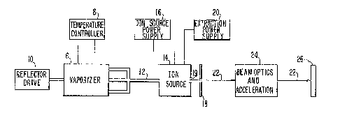
FIG. 1 is a block diagram illustrating an ion
beam system incorporating a vaporizer system in
accordance with an embodiment of the present invention;
FIG. 2 is a cross-sectional view of a vaporizer
in accordance with the prior art;
FIG. 3 is a cross-sectional view of a vaporizer
system in accordance with an embodiment of the
present invention; and
FIG. 4 is a partial cross-sectional view of the
vaporizer system taken through the line 4-4 of FIG. 3.
,
'
.
' ,.
:
~63~g
-- 7
Detailed Description
A block diagram of an ion beam system utilizing
a vaporizer system in accordance with one embodiment
is shown in FIG. 1. The vaporizer system includes
a vaporizer 6, a temperature controller 8 and a
reflector drive 10. The vaporizer 6 includes one
or more crucibles for generating a vapor of a
desired solid source material. One of the crucibles
is energized at a given time and supplies a vapor of
the source material through a conduit 12 to an ion
source 14. The operation of the vaporizer system is
described in detail hereinafter.
An ion source power supply 16 supplies the
necessary voltages and currents to energize the ion
source 14 so that the vapor supplied through the
conduit 12 is ionized. An extraction power supply
20 creates a strong electric field between an exit
aperture 19 in the ion source 14 and an extraction
electrode 18 positioned in front of the exit
aperture 19 to extract an ion beam 22 from the
source 14. In the case of an ion implantation
system, the ion beam 22 passes th,rough various beam
optics and acceleration elements 24 to form a high
energy beam of a desired spe~cies which is directed
at a target 26. The beam 22 may be scanned in one
or two dimensions ove,r the surface of target 26.
Ion implantation systems are generally known in the
art and are commercially a~ailable. An example of
'30
- - '
.'
~Z~63~9
-- 8
such a system is the Model 350-D available from
Varian ~ssociates, Inc., Extrion Division.
The vaporizer system of the present embodiment
may be used in other types of ion beam systems. For
example, in a reactive ion etch system, the ion
source 14 produces a relatively broad ion beam and
the focusing optics are omitted. A vaporizer system
is utilized to supply vapor to the ion source 14 in
any case where a gaseous form of the source material
is not available.
A vaporizer in accordance with the prior art is
illustrated in simplified form in FIG. 2. A
crucible 40, usually made of graphite or boron
nitride, has a cavity 42 which contains a source
material 44 in solid form to be vaporized. The
crucible 40 and the source material 44 are heated by
an electric heater 46 wrapped around the crucible
40. A removable cover 48 seals the opening 42 and
includes a tube 50 which feeds the resulting vapor
from cavity 42 to the ion source. The entire
crucible and heater are wrapped with a layer or more
of heat shield 51.
A cross-sectional view of a vaporizer system in
accordance with the present embodiment is shown in
FIG. 3. In general', the vaporizer system of the
invention employs one or more crucibles, each
containing a source material to be vaporized; a
radiation source for, heating one of the crucibles at
a time; and a reflector for directing energy from
- . . . .
.. . .
-
: . ' '
:. . :
.
63~
the radiation source at one of the crucibles. In
the case of multiple crucibles, the reflector is
movable so that energy from the radiation source can
be directed at a selected crucible. One of the
05 crucibles is heated by the radiation source, while
the others remain relatively cool. The diffic~lties
associated with turning individual heaters on and
off are eliminated.
Crucibles 60, 62 and 64 are equiangularly spaced
about a central axis 66 (perpendicuiar to the paper
in FIG. 3). A radiation source comprising a visible
and/or infrared emitting lamp 68 is mounted on or
near the axis 66. A reflector 70, which is
rotatable about the axis-66, directs-lamp radiation
that otherwise would impinge on all the crucibles to
a selected one of the crucibles 60, 62, 64. A
generally cylindrical heat shield 72 provides
thermal isolation between crucibles 60, 6~, S4 so
that the selected crucible can be raised to a high
temperature by radiation from lamp 68, while the
nonselected crucibles remain relatively cool. A
back surface 71 of the reflector 70 can be finished
in such a way ~for example, black anodizing) that
its thermal radiation absorption properties are
~5 enhanced, allowing it to act as a radiation heat
sink to those crucibles other than the one selected
to be heated. The reflector 70 can be water cooled
at its end (not shown) to remove heat absorbed by
the rePlector.
~'
~2763~
-- 10 --
The radiation source for heating the crucibles
60, 62, 64 is preferably a visible and/or infrared
source. One suitable lamp is a quartz halogen lamp
such as a Type QH500T3 manufactured by GTE, Sylvania
05 and having a rating of 500W. The lamp 68 has a
tubular envelope and is mounted with its axis
parallel to the axis 66 of the vapori~er system. A
temperature controller 8 (FIG. 1) supplies electric
power to lamp 68 in a controlled amount to increase
the temperature of the selected crucible as quickly
as possible during the war~-up period and to
maintain the temperature of the selected crucible as
stable as possible during the vaporization period so
as to feed a constant flow of vapor to the ion
source. Xt will be understood that other radiation
sources and wavelengths other than infrared are
included within the scope of the-present-invention.
The reflector 70 is fabricated from a metal such
as aluminum which has good thermal conductivity and
high reflectance to the-spectrum of the liqht
emitted by the lamp 68. The reflector 70 includes a
reflecting surface 74 on the side which faces the
lamp 68 and ab~orbing surface 71 on the opposite
side. The reflector 70 has a cross-section as shown
in FIG. 3 which is axially uniform and extends along
the length of lamp 68 so that substantially all of
the radiation from lamp 68 is directed toward the
selected crucible.
7~i3~
The reflecting surface 74 can have any suitable
shape for reflecting radiation from lamp 68 toward
the selected crucible. One preferred shape is
parabolic with the focus of the parabola coincident
05 with the axis of the la~p. As noted previously, the
reflector ~0 i5 rotatable about axis 66 to positions
in which it faces each of the crucibles 60, 62, 64.
It can be manually moved between positions, but is
preferably moved by reflector drive 10 (FIG. 1)
which can be controlled by a system computer or
other system con~roller. The reflector drive 10 can
be a motor or ratchet type mechanism.
Each of the crucibles 60, 62, 64 has the form of
a general:ly cylindical container with a cavity 60a,
62a, 64a, respectively, in which a source material
82 (FIG. ~) is placed. Each of the cavities 60a,
62a, 64a is sealed by a removable cover 84 havin~ a
tube or conduit 8S passing through it. The co~duit
86 directs vapor from the respective cavity-to the
ion source.
Cavities 60a, 62a~ 64a can ~e centrally located
in the respective crucibles. In a preferred
embodiment, however, the cavities are off-center so
that a portion ~0 of the crucible side wall clasest
to the axis 6~ is thicker than a portion 92 of the
crucible side wall remote from the axis 66, as shown
in FIGS. 3 and 4. The variable wall thickness to
some extent compensates for the fact that the
..
.
3LZ7631~
- 12 -
radiation from lamp b8 is applied unevenly to one
side of each of the crucibles. The variable wall
thickness tends to more evenly distribute the heat
supplied to the source material 82 contained in the
05 cavities 60a, 62a, 64a. With reference to PIG. 3,
the crucibles 60, 62, 64 each include an arc-shaped
cutout in the portion which faces the lamp 68 to
accommodate rotation of the reflector 70. This
configuration permits the crucibles to be positioned
in close proximity to the lamp 68 while permitting
the reflector 70 to rotate freely between positions.
In another preferred embodiment (not shown~, a
thin walled crucible is located in such a position,
and reflectors 72 is shaped in such a way, as to
L5 provide uniform or nearly uniform heating over the
surface of the crucible, resulting in a system`with
less thermal mass, which is turn helps to reduce
warm-up and cool-down time furth`er.
The embodiment illustrated in FIG. 3 includes
three crucibles 60r 62, 64 having equal radial
spacings from axis 66 and equiangularly spaced from
each vther. It will be understood that the
vaporizer system of the present invention can
inslude one or more cruci~les spaced around the
radiation ~cource with the number of crucibles
depending on the application~ The crucibles are
preferably fabricated from graphite which has good
chemical compatibilities to many materials to be
!
'' '
.
" ,' ', ' ' .
~ ' ' .
~27~
- 13 ~
vaporized, ~ood thermal conductivity and good
absorbing characteristics (e~ittance) to the
spectrum of light emitted by lamp 68.
The vaporizer system of the present invention
05 further includes the heat shield 72 which is
preferably fabricated from aluminum because of its
high reflectance to visible and/or infrared
radiation and its high thermal conductivity. The
heat shield 72 is generally cylindrical in overall
shape and includes cavities 94, 96, 98 for crucibles
60, 62, 64, respectively, and a centrally located
cavity 102 which contains the reflector 70 and the
lamp 68. Heat shield 72, which can be water cooled
at its end (not shownJ, provides thermal shielding
between the crucibles 60, 62, 64 so that one of the
cr~cibles can be heated while the other two remain
relatively cool. Preferably, the crucibles 60, 62,
64 are spaced from the heat shield 72 to prevent
thermal conduction ~rom the crucibles 60, 62, 64 to
the heat shield 72. The crucibles 60, 62, 64 are
supported in cavities 94, 96, 98, respectively, by
conventional end mounting means.
In an ion implantation application, the
crucibles 60, 62, 64 can contain arsenic,
phosphorous and antimony, respectively. In the
vaporizer system of the invention, a selected source
material can be vaporized rapidly, and the system
can be brought to an operating condition rapidly.
~ '-
. .
~27~3~
14 -
Virtually no vapor is obtained from the unheated
crucibles. Similarly, changes between species can
be accompllshed rapidly with minimum downtime.
Tha described embodiment provides the capability to
easily change the number of crucibles in a system
without changing the number of heat sources by
simply changing the illumination angle of the
reflector. The heat source is a separate part of
the system. The heat source can be serviced without
touching any of the crucibles which may contain
poisonous material. The crucible itself can be less
expensive and easily replaced because of the lack of
a dedicated heater and cumbersome electrical
connections.
While there has been shown and described what is
at present considered the preferred embodiments of
the present invention, it will be obvious to those
skilled in the art that various changes and
modifications may be made therein without departing
from the scope of the invention as defined by the
appended claims.
'' '
: . . . . .