Sélection de la langue

Search

Sommaire du brevet 1276623 

Énoncé de désistement de responsabilité concernant l'information provenant de tiers

Une partie des informations de ce site Web a été fournie par des sources externes. Le gouvernement du Canada n'assume aucune responsabilité concernant la précision, l'actualité ou la fiabilité des informations fournies par les sources externes. Les utilisateurs qui désirent employer cette information devraient consulter directement la source des informations. Le contenu fourni par les sources externes n'est pas assujetti aux exigences sur les langues officielles, la protection des renseignements personnels et l'accessibilité.

Disponibilité de l'Abrégé et des Revendications

L'apparition de différences dans le texte et l'image des Revendications et de l'Abrégé dépend du moment auquel le document est publié. Les textes des Revendications et de l'Abrégé sont affichés :

  • lorsque la demande peut être examinée par le public;
  • lorsque le brevet est émis (délivrance).
(12) Brevet: (11) CA 1276623
(21) Numéro de la demande: 1276623
(54) Titre français: EXTRACTEUR DE POTEAUX
(54) Titre anglais: POST PULLER
Statut: Périmé et au-delà du délai pour l’annulation
Données bibliographiques
(51) Classification internationale des brevets (CIB):
  • E21B 19/00 (2006.01)
  • E01F 09/623 (2016.01)
  • E04H 17/26 (2006.01)
(72) Inventeurs :
  • HOFF, HARAL (Etats-Unis d'Amérique)
(73) Titulaires :
  • HARAL HOFF
(71) Demandeurs :
(74) Agent: SMART & BIGGAR LP
(74) Co-agent:
(45) Délivré: 1990-11-20
(22) Date de dépôt: 1987-02-26
Licence disponible: S.O.
Cédé au domaine public: S.O.
(25) Langue des documents déposés: Anglais

Traité de coopération en matière de brevets (PCT): Non

(30) Données de priorité de la demande:
Numéro de la demande Pays / territoire Date
839,263 (Etats-Unis d'Amérique) 1986-03-13

Abrégés

Abrégé anglais


Abstract of the Disclosure
A fence post puller comprising a vertically disposed
support post having a base plate mounted on the lower end
thereof by means of a swivel or knuckle joint connection. An
elongated handle is pivotally connected to the upper end of the
support post and has a yoke pivotally secured to one end thereof
which is adapted to embrace and engage the post during upward
movement of the yoke.

Revendications

Note : Les revendications sont présentées dans la langue officielle dans laquelle elles ont été soumises.


The embodiments of the invention in which an exclusive
property or privilege is claimed are defined as follows:
1.
A fence post puller, comprising,
a foot portion having a generally planar base for engaging the
ground adjacent the post to be pulled,
an elongated support member having upper and lower ends,
a swivel connection connecting the lower end of said support
member to said foot portion, said support member
extending upwardly therefrom,
an elongated handle having first and second ends,
said handle being pivotally secured, inwardly and proximal to
said second end, to the upper end of said support member,
said first end of said first handle being movable between
upper and lower positions,
a yoke means pivotally secured to said second end of said handle
and comprising a generally T-shaped base portion having a
pair of spaced-apart yoke members extending therefrom
adapted to loosely embrace the post to be pulled, said
yoke members extending perpendicularly to the head of
said T-shaped base portion being pivotally connected to
said handle, and
a pin removably secured to and extending between said yoke
members for engagement with one side of said post when
said first end of said handle is moved towards its lower
position, to pull said post upwardly relative to the
ground.

2.
The post puller of claim 1, wherein said foot portion
further comprises two depending edges in engagement with the
ground, said edges disposed on opposite sides of said base.
3.
The post puller of claim 1, wherein said handle further
including a first handle portion extending from the pivotal
connection with said support member towards said first end, and
a second handle portion extending from the pivotal connection
with said support member towards said second end, said first and
second handle portions being angularly disposed within a
vertical plane with respect to each other, said first and second
handle portions being angularly disposed such that said second
handle portion is substantially horizontally disposed when said
first end of said handle is in its upper position.

Description

Note : Les descriptions sont présentées dans la langue officielle dans laquelle elles ont été soumises.

~6623
POST PULLER
Many types of post pullers have been previously provided
for pulling steel fence posts from the ground. For e~ample, in
U.S. Patent No. 4,161,310, a vertically disposed support member
having a base plate rigidly secured to the lower end thereof
supports a handle operated gripping means. The device of Patent
No. 4,161,310, as well a~ other prior art devices, is difficult
to use due to the fact that the ground adjacent the fence post
is very often irregular and the engagemen~ of the rigidly
mounted base plate with the ground results in the support member
thereof not being properly positioned relative to the post to
efficiently remove the post from the ground. Further, the prior
art devices are not convenient to use and are not efficient.
Therefore, it is a principal object of the invention to
provide an improved post puller.
A further object of the invention is to provide a post
puller including a base plate or foot portion having a swivel
connection connecting it to a vertically disposed support.
Yet another object of the invention is to provide a post
puller including an improved post gripping means.
A further object of the invention is to provide an
improved post puller including a handle which ls de~igned to
achieve the utmost efficlency in the po~t pulling operation.
Still another object of the invention is to provide a post
puller including a removable pin on the post gripping apparatus
so that the post gripping apparatus may be quickly and easily
positioned around the post to be pulled.
Yet another object of the invention is to provide a post
puller which is economical of manufacture, durable in use and
refined in appearance.

6Z3
These and other objects will be apparent to those skilled
in the art.
This invention consis~s in the construction, arrangements
and combination of the various parts of the device, whereby tAe
objects contemplated are attained as hereinafter more fully set
forth, specifically pointed out in the claims, and illustrated
in the accompanying drawings, in which:
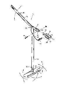
Figure 1 is a perspective view of the post puller of this
invention:
Figure 2 is a side view illustrating the post puller
positioned adjacent the post with the post puller in the post
gripping position:
Figure 3 is a view similar to Figure 2 except that the
post has been raised upwardly from the position of Figure 2:
Figure 4 is a view similar to Figures 2 and 3 except that
the handle of the post puller has been moved to its upper
position:
Figure 5 is a sectional view illustrating the relationship
of the post gripper and the post:
Figure 6 is a sectional view as seen on lines 6-6 of
Figure 5:
Figure 7 is a sectional view ~imilar to Figure S except
that the post gripper i5 illustrated in its non-engaging
position; and
Figure 8 is a partial exploded perspective view of the
swivel joint connection.
The post puller of this invention comprises an elongated
handle which is pivotally mounted on the upper end of a
vertically disposed support post. The lower end of the support
post has a swivel connection mounted thereon which is connected

~76623
to a base plate or foot portion. The handle comprises handle
portions which are angularly disposed with respect to each other
so that an extremely eficient post pulling operation is
provided. A post gripping apparatus is pivotally mounted to the
handle and includes a yoke portion which may be extended around
the post. A square pin is inserted through the yoke. As the
handle is moved downwardly, the square pin and the yoke engage
and grip the post so that the post is pulled upwardly from the
ground. When the handle is moved from its lowermost position to
its uppermost position, the yoke disenyages from the post and
moves downwardly therefrom for the next pulling stroke. The
swivel connection between the suppor~ post and the base plate
permits the post puller to be properly positioned adjacent the
post even if the ground around the post is irregular or is
sloped.
The post puller of this invention is referred to generally
by the reference numeral 10 while the reference numeral 12
refers to a steel fence post commonly referred to as bein~ of
the "T" type. Post puller 10 includes a base plate or foot
portion 14 having a swivel or knuckle joint connection 16
secured thereto. The lower end of a support po~t 18 is secured
to the upper end of the joint 16 dnd extends upwardly therefrom.
The numeral 20 refers to an elongated handle comprising
handle portions 22 and 24 which are angularly disposed with
respect to each other as illustrated in the drawing. Handle 20
is plvotally connected to the upper end of the support post 18
by means of the bolt assembly 26. As seen in the drawings,
handle 20 is pivotally connected to the support post 18 at the
juncture of the handle portions 22 and 24.
A pair of spaced-apart plates 28 and 30 are welded to the

~;~761~3
end of handle portion 24 and have a yoke 32 pivotally secured
thereto by means of bolt assembly 34. Yoke 32 includes a base
portion 36 having a pair of spaced-apart yoke members 38 and 40
extending therefrom. Yokes 38 and 40 are provid~d with square
openings 42 and 43 formed therein respectively adap~ed to
receive square pin 44 therein as will be described hereinafter.
Pin 44 has a chain 46 secured to one end thereof which extends
to the support post.
When it is desired to pull or remove a post 12 from the
ground, pin 44 is first removed from the yoke members and the
post puller 10 is positioned adjacent the post 12. The swivel
or knuckle joint connection between the base plate 14 and the
post 12 enables the post puller to be properly positioned
relative to the post even if the ground is irregular adjacent
the post. The swivel connection between the base plate and the
post enables the post 12 to be vertically disposed so as to be
parallel with the longitudinal axis of the post 12 so that the
most efficient pulling operation will be achieved.
As stated, pin 44 is removed from the yoke members 38 and
40 and the yoke members 38 and 40 are positioned on opposite
sides of the post as illustrated in the drawings. Pin 44 is
then positioned in the openings 42 and 43 of the yoke members 38
and 40 and the handle portion 22 is raised to its uppermost
position. Handle portion 22 is then moved downwardly which
causes the yoke 32 and the pin 44 to engage and grip opposite
sides of the post as illustrated in Figures 5 and 6 to pull the
same upwardly as the handle portion 22 is moved from its
uppermost position to its lowermost position as seen in Figure
3. For each downward stroke of the handle portion 22, the post
12 is moved upwardly approximately eight inches.

1~76~Z3
When handle portion 22 has reached its lowermost position,
handle portion 22 is then moved to its uppermost position as
seen in Figure 4. Movement of the handle portion 22 to its
uppermost position causes the yoke 32 and the pin 44 to
disengage from the post as seen in Figure 7 so that the yoke and
the pin may be moved downwardly relative to the post 12 in an
efficient manner. The operation is repeated until the post has
been removed from the ground.
The fact that the pin 44 is removably mounted in the yoke
32 permits the post puller to be positioned quickly and easily
adjacent the post without any component of the post puller being
required to be extended over the top of the post. Further, the
swivel or knuckle joint connection between the support post 12
and the base plate 14 ensures that the support post 18 will be
properly positioned as previously discussed. Thus it can be
seen that the invention accomplishes at least all of its stated
objectives.

Dessin représentatif
Une figure unique qui représente un dessin illustrant l'invention.
États administratifs

2024-08-01 : Dans le cadre de la transition vers les Brevets de nouvelle génération (BNG), la base de données sur les brevets canadiens (BDBC) contient désormais un Historique d'événement plus détaillé, qui reproduit le Journal des événements de notre nouvelle solution interne.

Veuillez noter que les événements débutant par « Inactive : » se réfèrent à des événements qui ne sont plus utilisés dans notre nouvelle solution interne.

Pour une meilleure compréhension de l'état de la demande ou brevet qui figure sur cette page, la rubrique Mise en garde , et les descriptions de Brevet , Historique d'événement , Taxes périodiques et Historique des paiements devraient être consultées.

Historique d'événement

Description Date
Inactive : CIB attribuée 2022-03-29
Inactive : CIB expirée 2016-01-01
Inactive : CIB de MCD 2006-03-11
Le délai pour l'annulation est expiré 2001-11-20
Lettre envoyée 2000-11-20
Inactive : TME en retard traitée 2000-01-10
Lettre envoyée 1999-11-22
Inactive : TME en retard traitée 1997-12-01
Accordé par délivrance 1990-11-20

Historique d'abandonnement

Il n'y a pas d'historique d'abandonnement

Historique des taxes

Type de taxes Anniversaire Échéance Date payée
TM (catégorie 1, 7e anniv.) - petite 1997-11-20 1997-12-01
Annulation de la péremption réputée 1999-11-22 1997-12-01
TM (catégorie 1, 8e anniv.) - petite 1998-11-20 1998-11-13
TM (catégorie 1, 9e anniv.) - petite 1999-11-22 2000-01-10
Annulation de la péremption réputée 1999-11-22 2000-01-10
Titulaires au dossier

Les titulaires actuels et antérieures au dossier sont affichés en ordre alphabétique.

Titulaires actuels au dossier
HARAL HOFF
Titulaires antérieures au dossier
S.O.
Les propriétaires antérieurs qui ne figurent pas dans la liste des « Propriétaires au dossier » apparaîtront dans d'autres documents au dossier.
Documents

Pour visionner les fichiers sélectionnés, entrer le code reCAPTCHA :


Pour visualiser une image, cliquer sur un lien dans la colonne description du document (Temporairement non-disponible). Pour télécharger l'image (les images), cliquer l'une ou plusieurs cases à cocher dans la première colonne et ensuite cliquer sur le bouton "Télécharger sélection en format PDF (archive Zip)" ou le bouton "Télécharger sélection (en un fichier PDF fusionné)".

Liste des documents de brevet publiés et non publiés sur la BDBC .

Si vous avez des difficultés à accéder au contenu, veuillez communiquer avec le Centre de services à la clientèle au 1-866-997-1936, ou envoyer un courriel au Centre de service à la clientèle de l'OPIC.

({010=Tous les documents, 020=Au moment du dépôt, 030=Au moment de la mise à la disponibilité du public, 040=À la délivrance, 050=Examen, 060=Correspondance reçue, 070=Divers, 080=Correspondance envoyée, 090=Paiement})


Description du
Document 
Date
(aaaa-mm-jj) 
Nombre de pages   Taille de l'image (Ko) 
Abrégé 1993-10-13 1 11
Dessins 1993-10-13 3 58
Revendications 1993-10-13 2 52
Description 1993-10-13 5 173
Dessin représentatif 2001-11-01 1 7
Quittance d'un paiement en retard 1997-12-08 1 171
Avis concernant la taxe de maintien 1999-12-19 1 178
Quittance d'un paiement en retard 2000-01-13 1 171
Avis concernant la taxe de maintien 2000-12-17 1 178
Taxes 1997-11-30 1 36
Taxes 2000-01-09 1 28
Taxes 1995-11-05 1 44
Taxes 1996-11-04 1 53
Taxes 1994-11-02 1 39
Taxes 1993-11-03 1 27
Taxes 1992-11-03 1 34