Note : Les descriptions sont présentées dans la langue officielle dans laquelle elles ont été soumises.
i276667
AR:WJW: jSS REQUEST 1171
VEHICLE WI~EEL CON5TRl[JCq~ION
This invention relates to styled wheels for vehicles, and more
particularly to a composite metal-elastomer automotive-type styled
vehicle wheel construction with a three-dimensional deeply contoured
ornamental outboard race, and to molding apparatus and method for
constructing such a wheel.
In the early 1970's Motor Wheel Corporationof Lansing, Michigan,
assignee of applicant herein, as well as its parent, The Goodyear Tire
& Rubber Company of Akron, Ohio, developed and introduced an improved
form of composite metal-elastomer styled wheel marketed under the
registered trademar~ "POLYC~ST". Such styled wheels provided an
automotive type wheel in which metallic parts of simple, conventional
configuration, for which manufacturing equipment was already
available, are utilized as the basic structural components to thereby
obtain a high stren~3th standardized wheel construction at minimum
cost. The aesthetically pleasing appearance was imparted to this
standard steel backbone by a permanently adhered ornamental plastic
body, either molded separately or in situ as a homogeneous one-piece
body or in the form of a plastic cover secured by an adhesive foam
body to the outboard side of the wheel. This provided an improved
anti-noise characteristic to the wheel and enabled the appearance
of the wheel to be readily and economically varied to suit different
customer's styling requirements without varying the basic structural
components of the wheel. Additional benefits resided in the side
impact cushioning to prevent damage
q~
1276667
to the wheel while retaining the high strength and impact resistance
advantages of ~he time-proven conventional ductile steel wheel
components. Wider variations in styling and contour configurations
were also obtained than were possible in the previous deep drawn
styled all-steel wheels.
Various embodiments of such "POLYCAST" wheels, as well as
methods and apparatus for producing the same, are set forth in the
following United States Patents assigned either to the assignee
herein or its parent, The Goodyear Tire ~ Rubber Company, which are
incorporated herein by reference:
No . 3,669,501 6/1972 Derleth
No. 3,756,658 9/1973 Adams
No. 3,762,677 1~/1973 Adams
No. 3,815,200 6/1974 Adams
No. 3,918,762 11/1975 Hampshire
No. 3,79~,529 2/1974 Thompson
No. 3,935,291 1/1976 Jackson
No. 3,956,451 5/1976 Adams
No. 4,39~,770 8/1983 Smith
Other prior art patents issued to unrelated parties and
directed to various facets of such styled composite metal and plastic
wheels include United States Patents 3,823,982 and 3,998,494 as well
as British Patent 1,290,946 (1972).
In the manufacture of such POLYCAST wheels, a portion of
the mold comprises a conventional metal vehicle wheel having a drop
center rim secured to a central disc or body having the usual bolt
circle holes and a central aperture so that the disc can be mounted on
an axle, drum or disc brake assembly. The metal wheel is employed
in conjunction with an upper back-up
~:76166~
-3- ~
clamp and lower mold part to define therewith a sealed cavity
for molding and attaching a three-dimensional contoured plastic
overlay, the overlay thus being molded in situ and permanently
attached to the outboard side of the wheel in the mold apparatus.
Preferably, the wheel forms the upper surface of the mold cavity
and a reaction mixture of a urethane elastomer liquid adhesive
material is injected or poured into the mold to fill the cavity
and contact the outboard surface of the wheel assembly. The
urethane material solidifies to form a high density non-cellular
elastomer body which permanently adheres to the outboard surface
of the wheel subassembly. The plastic overlay may also be
constructed from a lower density microcellular closed cell
urethane elastomer adhesive material. The urethane material
is allowed to solidify in the mold cavity and then the mold is
opened so that the wheel with the overlay securely adhered to
it may be removed from the mold. The overlay may then be painted
or otherwise covered with a decorative coating to provide a
finished metallic-appearing ornamental wheel. The urethane
elastomer thus forms a plastic body having a three-dimensional
contour which is permanently attached to the outboard side of
the wheel to provide a decorative surface, and the elastomer
overlay appears to be an integral portion of the metal wheel.
In almost all of such POLYCAST wheel designs the wheel
disc and plastic overlay are provided with a center through-
opening coaxial with the wheel hub and wheel spindle to provide
a suitable space for receiving the vehicle wheel spindle therein.
Customarily, a separate hub cap or center ornament is detachably
mounted in the center openlng of the outboard face of the wheel
overlay to close the wheel spindle cavity. Such hub caps are
usually made of chrome-plated or bright metal or suitable plastic
and are fashioned with a decorative styling complemental to the
wheel, and usually bear the vehicle manufacturerls trademark.
~276667 - -
--4--
Generally, in the past, two systems of hub cap
retention have been employed with such POLYCAST wheels. One
type of system is that disclosed, for example, in the above-
listed Derleth United States Patent No. 3,669,501 and the Smith
United States Patent No. 4,398,770 wherein a so-called metallic
"dixie cup" is attached directly to the metal disc of the wheel
and protrudes axially in an outboard direction therefrom to
define the wheel spindle cavity. The "dixie cup" then removably
receives at its hollow outboard end a suitable decorative hub
cap. While this system is quite workable and has been used
successfully in millions of POLYCAST wheels, the same is somewhat
expensive, both from the standpoint of manufacture of the "dixie
cup" itself as well as assembly to the disc.
The other type of ornamental retention employed in
such POLYCAST wheels is where the hub cap, whether of plastic
or metal construction, is secured only to the urethane material
of the plastic overlay and thus only indirectly to the metal
components of the wheel. Some examples of this type of hub cap
retention are illustrated in the aforementioned Hampshire United
States Patent No. 3,918,762 as well as in the Spisak United
States Patents Nos. 3,823,982 and 3,998,494. These indirect
attachment systems are advantageous in that they eliminate the --
aforementioned "dixie cup" insert, and, hence, the cost and the
weight of the same. However, such ornament retention is dependent
in part on the urethane foam properties, and for security and
reliability generally requires a relatively expensive urethane
material of relatively high density to provide sufficient
strength for secure attachment under adverse conditions. In
addition, uniformity in reten~ion strength from wheel to wheel
is difficult to maintain and particularly a problem if it is
desired to vary the urethane foam properties, such as hardness,
density, etc. Moreover, the current practice of designing
retention nubbins or recesses into the urethane foam around the
~276667
-5- ,
inner periphery of the wheel spindle cavity is severely limited
because of problems of die lock in the manufacturing process
as well as the limited strength properties of the urethane foam
material. The indirect attachment system also sets limitations
on the choice of urethane foam materials to be employed in the
plastic overlay due to the need to be concerned with the
temperature sensitivity of the urethane foam as well as its
compression set and creep properties.
Accordingly, objects of the present invention are to
provide an improved composite metal-elastomer construction of
the aforementioned "POLYCAST" styled wheel type which overcomes
the aforesaid problems of mounting the removable ornamental hub
cap to the outboard face of the wheel; provide uniform ornament
retention properties to the wheel independent of and superior
to that obtainable with the urethane material alone; enable a
broader range of selection of urethane materials which are lower
incost and weight without endangering center ornament retention;
provides a reteDtion system independent of the steel backbone
or disc of the wheel construction; accomplish these objectives
at less expense than other prior means of retention such as the
use of the aforementioned "dixie cup" attached to the steel
backbone or disc; provide an improvement in the retention force
over the aforementioned direct attachment systems; and eliminate
the concern over the temperature sensitivity of the urethane
foam material and its compression set and creep properties.
Another object of the present invention is to provide
an improved method of making a composite wheel of the above
character in an economical and reliable manner.
A further object is to provide improved mold apparatus
for practicing the aforementioned improved method to construct
the aforementioned wheel of the present invention.
1276667
--6--
Other objects, as well as features and advantages of
the present invention will become apparent from the following
detailed description taken in conjunction with the accompanying
drawings, wherein:
FIG. 1 is a fragmentary elevational view of an
exemplary embodiment of a vehicle wheel constructed in accordance
with the present invention as viewed from the outboard face
thereof, with certain portions broken away to better illustrate
detail;
FIG. 2 is a cross sectional view taken on the line 2-2
of FIG. l;
FIG. 3 is a plan view of a first embodiment of a
retainer employed in the embodiment of FIGS. 1 through 8~ the
retainer being shown by itself in its free state condition;
FIG. 4 is a rear elevational view of a conventional
plastic detachable wheel ornament hub cap utilized with the
embodiment of FIGS. 1 through 8;
FIG. 5 is a sectional view taken on the line 5-5 of
FIG. 4;
FIG. 6 is a fragmentary cross sectional view of the
detail shown in the circle labeled "6" in FIG. 2, but greatly
enlarged thereover;
FIG. 7 is a fragmentary top plan view of an improved
molding apparatus of the present invention employed in the
construction of the embodiment of the wheel shown in FIGS. 1 and 2;
~'276667
--7--
FIG. 8 is a cross sectional view taken on the line 8-
~of FIG. 3;
FIG. 9 is a fragmentary elevational view of the
outboard face of a modified wheel construction also inaccordance
with the present invention;
FIG. 10 is a cross sectional view taken on the line
10-10 of FIG. 9;
FIG. 11 is a fragmentary cross sectional view of the
portion of FIG. 10 indicated by the circle 11 therein, but
greatly enlarged thereover;
FIG. 12 is a fragmentary cross sectional view of a
modified mold apparatus of the present invention adapted for
making the modified wheel construction of FIGS. 9 through 11,
the mold being shown in partially closed position in FIG. 12;
FIG. 13 is a cross sectional view of the mold of FIG.
12 with the same shown in fully closed position ready for casting
of urethane;
FIG. 14 is~ a perspective ~iew of the modified retainer
employed in the wheel construction of FIGS. 9 through 11; and
FIG. 15 is a fragmentary rear elevational view of the
ornamental hub cap employed with the wheel construction of FIGS.
9 through 11.
Referring in more detail to the accompanying drawings,
FIGS. 1 and 2 illustrate an exemplary, but pre~erred, embodiment
of a wheel constructed in accordance with the present invention,
utilizing the apparatus and made by the method of the invention.
~276667
--8--
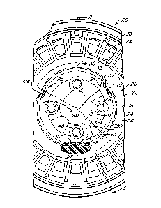
The wheel is generally designated 20 and comprises, by way of
a preferred example, a conventional drop center steel rim 22,
a central steel disc or body 24, and an ornamental three-
dimensional contoured overlay, generally designated at 26,
secured to the outboard face of disc 24 and to the outboard
surface of rim 22. Disc 24 is provided with a circle of bolt
holes 28 and a central wheel spindle aperture 30 so that wheel
20 can be removably attached to a wheel hub and associated disc
or drum brake assembly. For decorative purposes and for brake
ventilation, a plurality of cut-outs or vent holes 32 are
provided in disc 24. The particular confiquration of the steel
components of wheel 20, including rim 22 and disc 24, may follow
solely utilitarian considerations such as strength of the wheel
and ease and economy of manufacture, since the aesthetic
appearance of the wheel is determined largely by the three-
dimensional contour of the ornamental overlay 26. The three-
dimensional contours of overlay 26 in turn are determined by
the particular ornamental or aesthetic appearance desired by
the designer of wheel 20.
In the ornamental design of FIGS. 1 and 2, overlay 26
is provided with a central annular section 34 having a generally
smooth convex outer face 36 with a plurality of ins 38 radiating
outwardly from an outer peripheral wall 40 of section 34.
Pockets 42 are provided between each adjacent pair of fins 38
which extend axially inboard to provide a urethane aperture 44
within each disc aperture 32. Section 34 of overlay 36 has an
internal, slightly frusto-conical wall 50 diverging outboard
axially of the wheel and terminating at its outboard edge at a
shoulder surface 52 which extends radially outwardly from the
outer edge of wall 50 to an axially extending cylindrical surface
54. Wall 50 defines a relatively large cavity 56 in overlay 26
and is adapted to receive the vehicle wheel spindle therein in
a mounted condition of wheel 20.
~Lz76667 .
g
Wheel 20 is also provided with a removably attached
center ornament or hub cap 60 of conventional construction which
is releasably secured onto overlay 26 to cover the central
spindle cavity 56. Cap 60 is shown by itself in FIGS. 4 and 5
and comprises an injection molded plastic part having a circular
wall 62 with a slight convex curvature outboard of the wheel
to match the curvature of face 36 of overlay 26. Cap 60 also has
a cylindrical flange 64 which extends axially from the inboard
face of the cap and which is radially inwardly offset from the
outer peripheral edge 66 of wall 62. The inboard free edge of
flange 64 has an integral annular cam lip 68 protruding radially
outwardly therefrom. Lip 68 has a cam surface 70 inclined at
an angle of about 30 to the axis of cap 60 with a radiused
outer edge 72 and a generally radially extending surface 74 on
the outboard side of lip 68. Lip 68 has three equally angularly
spaced nubbins 76 (FIG. 4) protruding radially outwardly
therefrom.
In order to provide snap-in retention of cap 60 onto
overlay 26, and also in accordance with past practice, section
34 of overlay 26 is provided with three equally angularly spaced
nubbins 80,82,84 ~FIG. 1) which protrude radially and inwardly
from wall 50 adjacent the outboard edge thereof. Referring to
nubbin 80 (FIGS. 1, 2 and 6), the same extends circumferentially
of opening 56 about 25. The radially inwardly facing surface
of each nubbin 80,82,84 is defined by a pair of inclined surfaces
86 and 88 which extend at about a 15 angle to wall 50 in inboard
and outboard directions, respectively, and converge at an apex
or ridge line 90 in the center of nubbin 80 axially of the wheel.
In accordance with a principal feature of the present
invention, wheel 20 is provided with a hub cap retention
reinforcing retainer 100 which, in the embodiment of FIGS. 1-8,
is in the form of a tempered spring steel wire 102 having a
~27~667
-10-
generally circular configuration. Wire 102 is split such that
its free ends 104 and 106 define a gap therebetween in the free
state condition as shown in FIG. 3. Wire 102 is formed to a
given diameter, for example, .172 mm, selected to exceed the
diameter of wall 50 at nubbins 80,82,84 by a given amount, for
example by 16 mm, to provide a firm embedment of wire 102 in
the urethane material of overlay 26. Retainer 100 is molded
into this material, as set forth in more detail hereinafter, so
as to thus be fully encapsulated, except at three hub-cap
retention contact points coincident with the nubbins 80,82,84.
To this end, retainer 100 is provided with three equally angularly
spaced inwardly bowed portions 108,110,112 each having a radius
of curvature, for example 25 mm, such that each bowed portion
dips radially inwardly to be substantially tangent with the
center of each associated nubbin, as best seen in FIGS. 1, 2 and
6. The bowed portions are also circumferentially oriented such
that their apices surface at the circumferential center of the
associated nubbin crest 90 relative to each nubbin. Hence,
each urethane retention nubbin 80,82,84 is materially
structurally reinEorced by the associated wire bends embedded
therein.
When retainer 100 is made of tempered spring steel
wire, the retainer itself can provide substantially all of the
resilience to accommodate the snap-in retention of hub cap 60.
~lternatively, other materials with different properties may
be specified for retainer 100, ranging from soft steel to certain
plastic materials with low creep and good fatigue properties.
In such instances the retainer 100 may have less resilience,
but still be flexible, and serve more as a back-up reinforcement
for the urethane mater;al of overlay 26, with the latter material
being relied upon to provide a good portion of the resiliency
or spring-bac~ force for the snap-in retention of cap 60. The
split in retainer 100 enables the same to more freely contract
1276667
and expand, both during mold release and in subsequent operation
relative to insertion and remova~ of hub cap 60 to overlay 26.
FIGS. 7 and 8 illustrate an improved molding apparatus and
improved method of making wheel 20 utilizing such apparatus, which
incorporate many of the features of the molding apparatus and method
illustrated in conjunction with FIGS. 7-11 of the aforementioned
~dams United States Patent 3,762,677. Reference is made to the
molding apparatus or mold 200 described in columns 11-16 of the '677
patent, and identical reference numerals are employed in FIGS. 7 and
8 to identify elements alike in structure and/or function.
Mold apparatus 200 comprises three main components; namely, a
lower mold part 202 (FIG. 8), the metal vehicle wheel subassembly
22-24, and an upper half 206 which serves as a back-up support for
clamping wheel 22-24 onto mold part 202. Lower mold part 202 has
an annular lip in the form of a resilient seal 224 adapted to seat
against an annular portion of the outboard face of rim 22. Mold part
202 also has a surface 230 on its upper side radially inwardly of
seal 224 adapted to define, with the outboard face of wheel subassembly
22-24, a mold cavity in which the decorative plastic overlay 26 is
cast, the same being suitably contoured to provide the ornamental
configuration to form the outboard face of wheel 20 as shown in FIGS.
1 and 2.
To assembly mold 200, wheel subassembly 22-24 is placed against
part 202 as shown in FIG. 8 with flange 226 of rim 222 resting on or
in light contact with seal 224. This also lightly seats the bolt
circle portion 214 of disc 24 against an annular inner seal 234
mounted on the upper face of a mold pedestal 235 which in turn is
suitably secured to the center of face 230 of mold part 202. Pedestal
235 provides a core to
~L276667
-12-
form the wall 50 defining the wheel well cavity 56 and overlay
26. Seal 234 is adapted to seal the mold cavity around its
inner perimeter in the fully seated condition of wheel sub-
assembly 22-24 on mold part 202.
The upper mold part 206 is then urged downwardly
against wheel sub-assembly 22-24 as shown in FIG. 8. Mold part
206 has a resilient annular pad 236 having a configuration on
its underside adapted to seat against the inboard face of disc
24 to thereby force the disc-rim subassembly 22-24 further
toward part 202 and then retain parts 202 and 22-24 in sealing
engagement. Upper part 206 also has an annular seal 237 radially
inwardly of seal 236 which seats on the bolt circle portion 214
of the inner face of disc 24. A steel funnel 312 is secured on
the upper surface of clamp 206 and has a neck 314 which extends
downwardly through a washer seal 316 and seal 237 into engagement
with a pour opening 290 provided in disc 24 between a pair of
adjacent bolt holes 28 therein. Pedestal 235 has a notch 288
in the upper surface thereof which registers with pour opening
290 and neck or spout 314 to sexve as a sprue for directing the
liquid urethane reaction mixture into the mold cavity during
pouring of the mold. Further details and features of mold 200
as well as details of structure, function and operation of
various elements thereof may be had by reference to the
aforementioned '677 patent.
In accordance with the present invention, ornament
retainer 100 is assembled to mold part 202 prior to seating of
the disc-rim subassembly 22-24 thereon. Such assembly simply
involves slipping retainer 100 downwardly along the sloping
frusto-conical side ~all 239 of pedestal 235 until the bowed-
in portions 108, 110 and 112 respectively register with and
snap into the associated nubbin cavities 80', 82' and 84' already
provided in pedestal 235 in accordance with previous practice
lX76667
to form nubbins 80, 82 and 8a., respectively. The resilience
of wire 202 allows it to expand radially as bowed-in portions
108,110,112 slide down surface 23g, the gap between the free
ends 104 and 106 of wire 102 widening as this occurs. This
resilience also causes the wire 102 to snap back to its.captured
position shown in FIGS. 7 and 8 with the bowed portions 108-
112 seated in nubbin cavities 80'-84'. In this condition wire
102 is self-supporting so as to protrude radially outwardly
from pedestal 235 into the mold cavity, retainer 100 thereby
being properly seated and oriented for embedment in the liquid
urethane reaction mixture when poured into the mold cavity to
produce overlay 26 as shown in FIGS. 1 and 2.
After the urethane has cured and solidified, the
foregoing mold assembly procedure is reversed to open mold 202
and to remove the finished wheel 20 therefrom, the ornamental
plastic overlay 26 with retainer 100 embedded therein having
now become a permanent decorative fixture on disc-rim sub-
assembly 22-24. During upward stripping of wheel 20 from mold
part 202, nubbins 80-84 and associated retainer bowed portions
108-112 are expanded outwardly by the upper slope o~ nubbin
cavities 80'-84' until clear of pedestal 23~, whereupon the
same spring back to their as-cast position in the finished
product as shown in FIGS. 1 and 2.
Referring to FIGS. 9-11, another embodiment 20' of
an improved wheel constructed in accordance with the present
invention is illustrated fragmentarily therein. Structural
elements identical to those previously described in conjunction
with wheel embodiment 20 are given like reference numerals and
reference numerals raised by a prime suffix indicate structure
corresponding in function and operation to that previously
described~ Thus, wheel 20' has a metal disc 24 and associated
metal rim 22 (not shown), and an ornamental elastomeric urethane
1276667
-14- ~
body 26' molded against the outboard face of disc 24 and
contiguous portions of rim 22 to provide a decorative co~tour
on the outboard face of the wheel. The center of overlay 26' has
a wheel spindle cavity 56' defined generally by an annular wall
50' made up of a large diameter cylindrical wall 50a coincident
with wheel disc center opening 30 and extending in an outboard
direction therefrom. Wall SOa intersects a frusto-conical wall
50b which extends therefrom in an outboard direction to an
intersection with a concave wall 50c. Wall 50c in turn merges
with a radius wall 50d which, as bes~ seen in FIG. 11, extends
radially outward to merge with a hub cap seating surface 52'
bounded by an internal shoulder 54' tFIGS. 10 and 11).
Wheel 20' is adapted to detachably receive a center
ornament or hub cap 60' which, like hub cap 60, is of conventional
construction. However, cap 60' diffPrs from hub cap 60 having
a plurality of angularly spaced spring fingers 64' ~FIG. 15),
each having a foot portion 65 (FIG. 11) crimped under a return
bent outer edge 66' of hub cap 60'. Each finger 64' has a
griping portion 74' extending axially at an incline radially
outwardly from foot 65 and terminating in a camming portion 70'
bent radially inwardly from portion 74'. Spring fingers 64'
are thus adapted to be flexed radially inwardly as the hub cap
60' is inserted axially in an inboard direction into center
opening 56', the fingers being yieldable to slide past the
minimum constricting surface 50d at the entrance to cavity 56'
and then spring back outwardly to releasably grip the hub cap
with the same seated against shoulder 52' of overlay 26', as
shown in FIGS. 9-11.
In accordance with the principal feature of the present
invention, snap-in wheel retention of hub cap 60' is indirectly
to the elastomeric material of overlay 26' rather than directly
to the metallic disc 24 of the wheel. Such retention is again
76667
-15-
provided in a uniform and consistent manner regardless of variations
in the material of overlay 26' by means of a modified hub cap retention
reinforcing retainer 100' embedded into the elastomeric material of
overlay 26'. Retainer 100', like retainer 100, is in the form of a
resilient wire spring with angularly spaced portions surfacing at
the constricting wall surface 50d. However, as best seen in FIG.
14, retainer 100' comprises a continuous loop of steel wire 102'
suitably shaped to form an interrupted circle defined by four curved
segment portions 114, 116, 118, 120 interconnected by four radially
outwardly and axially inwardly extending bite anchor portions 122,
124, 126, 128. Retainer 100' is embedded in the urethane material
of overlay 26' so as to be positioned as shown in FIGS. 9, 10 and
11 relative to spindle opening 56'. As best seen in FIG. 11, each of
the arcuate segments 114-120 lies just beneath the surface of the
urethane material, the circular wire stock having a smaller radius
of curvature than that of surface 50d and being tangent thereto at
the minimum diameter portion of wall 50'. The bite portions 122-
128 extend back from the associated segment portions in an inboard
direction and radially outwardly at a greater angle than wall surfaces
50c and 50b, so as to serve as anchors in the urethane material of
overlay 26' for the reinforcing spring sections 114-120.
In operation of the hub cap retention system of wheel 20',
cap 60' is inserted from left to right as viewed in FIGS. 10-11 into
opening 56' to first bring the cam portion 70' of each finger 64'
against surface 50d. As cap 60' is pushed further inwardly (to the
right as viewed in FIGS. 10-11), the spring fingers of the cap will
yield radially inwardly due to their resilience, and also the urethane
material will yield radially outwardly, as will retainer 100', until
the fingers reach the point where they can expand as they register
with concave wall surface 50c, portion 74' of each finger thus being
3L~7Ç;667
-16-
locked axially inwardly and radially outwardly of the associated
wire segment 114-120.
It will thus be seen that reinforcing retainer 100',
like retainer 100, provides uniform ornament retention
properties to the wheel 20' independent of and superior to that
obtainable alone with the urethane elastomer material employed
in overlay 26'. Since ornament retention is no longer dependent
on the urethane foam properties, the wheel designer has the
option of using less expensive and/or lighter weight materials
without fear of loss of hub cap retention. Again, retainer
100', like retainer 100, is molded in situ in the urethane
material of the decorative overlay and is fully encapsulated
therein, except at the retention contact points, and is not
attached, other than indirectly through the urethane material,
to the steel disc 24. Whatever resiliency, flexibility or
stiffness parameters may be desired in retainer 100' can be
specified by the designer, for example ranging from soft steel
to tempered spring wire. It will also be understood that other
design configurations of split or continuous retention
reinforcing members may be provided in accordance with the
invention, including stamped sheet metal members or injection
molded plastic members. ~lthough metal is the material of
choice in practice of the present invention, certain plastic
materials wi~h low creep or good fatigue properties are also
acceptable selections for use in retainer 100'. Retainer 100',
as with retainer 100, thus eliminates the wheel designer's
concern over the temperature sensitivity of the urethane foam
of the overlay 26' as well as its compression set and creep
properties because ornament retention properties may be
maintained uniform throughout a variety of designs independent
of the urethane foam properties.
~2~ 6~
-17-
Referring to FIGS. 12 and 13, wheel 20l is preferably
constructed using the modified mold apparatus 200' shown therein.
Modified mold apparatus 200' differs from apparatus 200 in that
the lower mold part 202' does not have the central pedestal
235. Instead a short annular core piece 400 is suitably fixed
to surface 230' coaxial with the mold and wheel center, and is
shaped to form the center opening wall surface 50d of overlay
26'. Upper mold part 206' differs from back-up 206 in having
a core structure 402, which is secured to its underside centrally
thereof by a stud 404. Core structure 402 is a multi-piece
lamination comprising a circular steel back-up plate 406 seated
in a circular cavity 408 in the under surface of upper mold
part 206'. A resilient cushion-seal 410 is clamped against the
under side of back-up 406 by a metal disc 412 having a central
threaded bore 414 threadably receiving stud 404. The lower
face 413 of disc 412 has a resilient disc 416 secured thereto by
a suitable adhesive.
In the closed condition of mold 200', as shown in
FIG. 13, a cylindrical surface 418 of disc 412 defines a mold
cavity surface which forms overlay wall 50a, and a frusto-
conical surface 420 of disc 412 defines the mold cavity surface
which forms overlay wall 50b. In the partially opened or
released condition of upper mold part 206' shown in FIG. 12,
cushion-seal 416 has a frusto-conical outer surface 422 forming
a smooth extension of surface 420 in the relaxed state of seal
416. Upper cushion-seal 410 has a cylindrical outer periphery
424 in its relaxed condition having an outside diameter providing
a slight clearance with the inner periphery of disc center
opening 30, and of the same diameter as disc surface 418. The
lowermost face 426 of seal 416 has the same diameter as the
upper face 428 of pedestal 400.
~27~667
-18-
In the operation of modified mold apparatus 200', and
prior to placing the wheel disc-rim subassembly 22-24 onto lower
mold part 202', retainer 100' is snugly seated on pedestal 400
as shown in FIG. 12 with segments 114-120 engaging the concavely
curved peripheral surface 401 of pedestal 400. In thiscondition,
retainer 100' is self-supporting and bite portions 122-128
protrude upwardly and outwardly away from the center of the
mold cavity. Disc-rim subassembly 22-24 is seated on the lower
mold part 202' as described previously, and then the upper mold
part 206' is brought down onto the disc-rim subassembly so as
to insert core structure 40~ downwardly through the disc opening
30' until surfaces 426 and 428 abut. Then further clamping
pressure is exerted downwardly on part 206 to produce one final
small increment of motion wherein, as can be seen by comparing
FIGS. 12 and 13, funnel 314 enters pour opening 290 and both
seals 410 and 416 are compressed axially so as to bulge radially
outwardly to their positions shown in FIG. 13. In this
compressively stressed condition upper seal 410 is bulged
outwardly into sealing engagement with the inner periphery of
disc opening 30. Likewise, lower seal 416 has been bulged
radially outwardly to provide the exterior contour which forms
the overlay wall 50c. This squeeze pressure also insures a
tight seal between surfaces 426 and 428 to minimize flash at
the parting line of the mold.
The li~uid urethane reaction mixture is then poured
into the mold cavity defined by and between the lower mold
surface 230, the outboard face of disc 24 and associated rim 22
and laminated core structure 402. After the urethane reaction
mixture has cured upper mold part 206 is released and raised
to withdraw the same from disc 24, and then the finished metal-
elastomer composite styled wheel is removed from the mold with
the urethane overlay 26' permanently adhered as a decorative
body to the outboard face of the wheel. Retainer 100' is thus
~ 276667
--19-- ,
now fully and permanently embedded in the urethane material of
overlay 26', ready to perform its function as a hub cap retention
reinforcement and provide the aforementioned improved results
and advantages of the invention.