Sélection de la langue

Search

Sommaire du brevet 1277302 

Énoncé de désistement de responsabilité concernant l'information provenant de tiers

Une partie des informations de ce site Web a été fournie par des sources externes. Le gouvernement du Canada n'assume aucune responsabilité concernant la précision, l'actualité ou la fiabilité des informations fournies par les sources externes. Les utilisateurs qui désirent employer cette information devraient consulter directement la source des informations. Le contenu fourni par les sources externes n'est pas assujetti aux exigences sur les langues officielles, la protection des renseignements personnels et l'accessibilité.

Disponibilité de l'Abrégé et des Revendications

L'apparition de différences dans le texte et l'image des Revendications et de l'Abrégé dépend du moment auquel le document est publié. Les textes des Revendications et de l'Abrégé sont affichés :

  • lorsque la demande peut être examinée par le public;
  • lorsque le brevet est émis (délivrance).
(12) Brevet: (11) CA 1277302
(21) Numéro de la demande: 1277302
(54) Titre français: SUPPORT POUR TUYAU SOUPLE ET CABLE
(54) Titre anglais: HOSE AND CABLE SUPPORT
Statut: Durée expirée - après l'octroi
Données bibliographiques
Abrégés

Abrégé anglais


ABSTRACT
An apparatus for suspending hoses or cables which consists
of an elongate support having a support surface in the shape of
an arch with a vertex, depending haunches and intrados. A hose
or cable may be supported upon the vertex and haunches of the
arch. At least one strap is secured transversely to the support.
Loops or rings are provided for attaching the strap to a
suspension line. The invention provides a simple and thus
inexpensive support while minimizing the risk of damage to the
hose due to crimping or to the supporting strap due to a rough
surface of the supported article.

Revendications

Note : Les revendications sont présentées dans la langue officielle dans laquelle elles ont été soumises.


The embodiments of the invention in which an exclusive
right or privilege is claimed are defined as follows:
1. An apparatus for suspending hoses or cables,
comprising, in combination:
(a) an elongate support having a first end and a second
end and including a support surface in the shape of an
arch extending from the first end to the second end,
said arch having a vertex, depending haunches and
intrados, such that a hose or cable may be supported
upon the vertex and haunches of the arch;
(b) the intrados being generally integral with a generally
rigid web which reinforces the intrados such that the
radius of the arch generally does not vary under the
weight of the hose or the cable; and
(c) a suspension strap means secured to the exterior
section transversely of the arch and having means to
permit the strap means to be attached to suspension
means to suspend the apparatus;
(d) the support including side wall sections adjacent the
support surface and defining, with the support surface
and the side wall sections, a channel for receiving a
respective hose or cable, said channel having a
generally circular cross-section, whereby a
substantial portion of the part of the hose or cable
is enveloped by the support.
2. An apparatus for suspending hoses or cables,
comprising:
(a) An elongate, arcuately shaped support having a first
end and a second end, said support including an outer support
surface for engaging the hose or cable to be suspended, and an
inner, concave surface defining an intrados, said support
including a first haunch defining said first end of said support
and a second haunch defining said second end of said support;
(b) a substantially rigid web extending inwardly from said
intrados to reinforce said support and to maintain said first and
second haunches at a defined angle relative to one another, said

web having an aperture formed therethrough; and
(c) strap means for suspending said support with a hose or
cable supported therein, said strap means being adapted to pass
through said aperture in said web.
3. An apparatus for suspending hoses or cable,s
comprising, in combination:
(a) an elongate, arcuately shaped support;
(b) said support having a first end and a second end and
including an outside surface of the arcuately shaped support,
said outside surface being a support surface portion of a
concavely shaped cross-sectional configuration complementary with
the cross-section of a hose or cable to be suspended by the
apparatus, said concavely shaped cross-sectional configuration
being defined by a bottom wall section and two opposed side wall
sections;
(c) said support surface having the shape of an arch with a
first haunch at said first end, a second haunch at said second
end, and a vertex portion disposed between, and being integral
with, said first and second haunches;
(d) said support further having an integral intrados which
forms an inside surface of the arcuately shaped support, said
inside surface facing oppositely from said support surface
portion;
(e) the intrados including a web integral with said bottom
wall section, said web extending from a point near said first end
to a point near said second end and having an outermost surface
portion spanning the arch thus gradually increasing the thickness
of the bottom wall section in a direction from the respective
haunch to the vertex portion, whereby the bottom wall section is
at its maximum thickness at the vertex portion and its minimum
thickness at each of said haunches;
(f) suspension strap means for suspending the apparatus
with a hose or cable supported therein, said suspension strap
means being attached to said web at a point near said vertex
portion, and extending about the side wall sections;
whereby the web reinforces the intrados such that the
radius of the arch generally does not vary under the weight of
11

the hose or the cable when the support is suspended solely at
said point near the vertex portion of the arch.
4. An apparatus as defined in one of claims 1 or 3, wherein
the side wall sections have upper edge portions defining
therebetween a slot opposite the support surface, whereby the
hose or cable may be inserted into the interior channel upon
enlargement of the slot by spreading apart the side wall
sections.
5. An apparatus as defined in one of claims 1, or 3,
wherein the support is made of molded polymer plastic material and
wherein the strap means is embedded in said generally rigid web
generally equidistant between the first end and the second end of
the support, but freely overlaps outer surfaces of the side wall
sections.
6. An apparatus as defined in one of Claims 1, 2 or 3,
wherein the support has a first end and a second end, the strap
means being secured to said generally rigid web substantially
equidistant between the first end and the second end of the
support.
7. An apparatus as defined in one of claims 1, 2 or 3, the
support being made of a polymer plastic material and the strap
means being embedded in the support.
8. An apparatus as defined in claim 7, the support having
an exterior surface with a transverse groove at each of the ends
such that a clamping member may be accommodated to secure a hose
or cable within the interior channel of the support.
9. An apparatus as defined in claim 6, wherein said side
wall sections have inner surface portions thereof, provided with a
plurality of transversely extending raised ribs.
12

Description

Note : Les descriptions sont présentées dans la langue officielle dans laquelle elles ont été soumises.

7730~
The present invention relates to an apparatus for
suspending hoses or cables.
BACKGROUND OF T~ INVE~ION
There are numerous industrial and commercial
applications which require hoses or cables to be
suspended from a support structure. At the present time
a "sling" is used to suspe~nd the hose or cable. The
"sling" consists of a strap formed in a loop wh~ch
extends transversely such that hose or cable rests on
the strap. The force exerted by its own weight
sometimes causes the hose or cable to become crimped
over the strap. The stress exerted upon the material
from such crimping ultimately leads to a failure o~ the
cable or hose.
SUMMARY OF THE INV~NTION
What is required is an apparatus for suspending
hoses or cables which will prevent crimping.
According to the present invention there is
provided an apparatus for suspending hoses or cables,
which is comprised of an elongate support having a
support surface in the shape of an arch with a vert~x,
depending haunches and intrados. A hose or cable may
supported upon the vertex and haunches of the arch. At
least one strap is secured transversely to the support.
Means are provided for securing the strap to a
suspension line.
This supporting configuration limits the extent to
which the hose or cable will be bent to a controlled
radius, selected with a view to minimizing the risk of
damage due to crimping. The permissible radius of the
arch varies with the diameter, weight and material of

1~7'~;30~
the hose or cable.
Although beneficial results may be obtained from
sing the described apparatus, the straps do a more
effective job if they underlie the hose or cable. Even
more beneficial results may therefore be obtained if the
strap i5 secured to the intrados of the support.
Although beneficial results may be obtained from
10 using the described apparatus, it i5 desirable that
sl:eps be l;aken to ensure that there is no slippaye of
the strap. Even more beneficial results may therefore
be obtained if the support is made of a polymer plastic
material and the strap is embedded in the support.
Although beneficial results may be obtained from
using the described apparatus, there is a possibility
t~lat the hose or cable may shift laterally in the
support during movement. Evzn more beneficial results
20 may therefore be obtained if the support has side walls
adjacent the support surface, such that the side walls
form an interior channel which limits transverse
moveMent of the hose or cable.
Although beneficial results may be obtained from
using the described apparatus, if overloaded the arch
shaped support structure may collapse. E~en more
beneficial results may therefore be obtained if the
intrados is reinforced.
Al-though beneficial results may be obtained from
using the described apparatus, the stress upon the strap
is reduced if the support is balanced. Even more
beneficial results may therefore be obtained if the
35 support has a first end and I sec~nd end, an1 the strap
:

~ ~t7~73()-~
i5 secured subs-tantially equid:istant between the first
end and the second end of the support.
Although beneficial results may be obtained from
using the described apparatus, 50me hoses and cables are
so heavy that they cannot be readily loaded onto the
support. Even more beneficial results may therefore be
obtained if a single strap is used having a first
10 portion which extends from one side of the support
terminating in a firs-t end and a second portion which
ex-tends from the opposed side oE the support terminatiny
in a second end, -the second portion being longer -than
the first portion, the first end and second end being
15 formed in a loop, such that when the second portion is
placed under a hose or cable and then fed through the
loop in the firs-t portion a force exerted by a
suspension line secured to the loop on the second
portion will cau~e the second portion to pass through
20 the loop in the first portion thereby drawing the
support into a position where the support surface
underlies the hose or cable.
~RIEF D~SCRIPTIO~ OF T~ DR~T~G~
These and other features of the invention will
become more apparent from the following description in
which reerence is made to the appended drawings,
wherein:
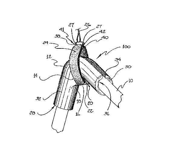
FIG~R~ 1 is a perspective view of a first pre~erred
30 embodiment of the invention.
FIG~E ? is a perspec-tive view of a second
preferred embodiment of the invention.
~ I6~R~ 3 is a perspective view of a third preferred
embodiment of the invention in a first position.
3~

~77~3()~::
FIGURE 4 is a perspective view of a -third preferred
embodiment of the invention in a second position.
FIG~æ~ 5 is a perspective view of a third preferred
embodiment of the invention in a third position.
_EET~ILDD D3 !:SeRIPTIOl~ _OF TEZ PR~FE~D_ EMIBODI~E~IT
The preferred embodimen-ts will now be described
with reference to FIG~ES 1 thro-uyh 5. The preferred
embodiments are apparatus for suspendirlg hoses or
10 cables. Three embodiments are illus-trated, a first
embodiment generally desig]nated by reference numeral
100, a second embodiment generally designated by
reference numeral 200, a~d a third embodiment ~enerally
designated by reference numeral 300.
1~
Each of the embodime~ts are variations on a basic
structure. This basic structure consists of an elonga-te
support 12 having a support surface 14 in the shape of
an arch. The par-ts of arch shaped Ruppor-t surface 14
20 which are rele~ant to the description which follows are
a verte~ 16, depending haunch~s 18 and 20, and an
intrados 22 (the inside curve of the arch). A hose or
cable 10 may supported upon ver-tex 16 and haunches 18
and 20 of arch shaped support surface 14. A strap 24 is
25 secured -transversely to support 12 within intrados 22 of
support surface 14. Strap 24 is intended to be attached
-to a suspension line 26.
The commercial production models of the basic
30 structure have improvemen-ts ~dded to increase their
serviceability. Suppor-t 12 is made of a polymer plastic
material, this enables strap 24 to be imbedded into
support 12 thexeby eliminating any possibili-ty of strap
24 slipping or becoming detached. In-trados 22 is

~Z~773~;~
reinforced to ensure -that -the selected radius of arch
shaped support 14 is maintained when a load is placed on
suppor-t 12. S-trap 24 is positioned ~ubstantially
equidistant between the respective ends of support 12,
which balances the load imposed by ho~e or cable 10 and
thereby reduces the stress upon strap 24.
First embodiment 100, as illustrated in FIGURE 1,
consists of an elongate support 12 o~ a polymer plastic
10 material having a support surface 14 in the shape of an
arch. Arch shaped support surface 14 has a vertex 16,
depending haunches 18 and 20~ An intrados 22 underlying
support surface 14 is reinforced. Support 12 has a
first end 28 and a second end 30. Support 12 has side
15 walls 32 and 34 positioned adjacent suyport surface 14
which form an interior channel 36. A strap 24 is
embedded in intrados 22 substantially equidistant
between firs-t end 28 and second end 30 of upport 12.
Strap 24 has opposed ends 38 and 40 formed into loops 41
20 and 42 thereby permitting strap 24 to be attached to a
suspension line 26.
In order to use first embodiment 100 a hose or
cable 10 is man~ally positioned within interior channel
25 36 of support 12. When positioned within in-terior
channel 36 hose or cable 10 is supported by verte~ 16
and haunches 18 and 20 of support surface 14. Hose or
cable 10 is prevented fro~ transverse movem~nt by side
walls 32 and 34. Ho~e or cable 10 is preven-t0d Ero~
30 movem~nt longitudinally in interior channel 36 by
friction. Strap 24 is then connected to a suspension
line 26 by:inserting hooks 27 secured to suspension line
26 through loops 41 and 42. As suppor-t 12 is raised by
suspension line 26 the ~eight of hose or cable 10 is
3~ supported by support sur-face 14. The arch shape of

73~1~
support surfac~ 14 prevents the crimping or bending of
hose or cable 10.
Second embodimerlt 200, as illustrated in FIGURE 2,
consists of an elongate support 12 of a polymer plastic
material haviny a support surface 14 in the shape of an
arch. Arch shaped support surface 14 has a vertex 16
and depending haurlches 18 and 20. Suppor-t 12 ha~ a
reinforced intrados 22 which underli~s the arch of arch
10 shaped swpport surface 14. Support 12 has a first end
28 and a second end 30. Support 12 has side walls 32
and 34 adjacent support surface 14 which form an
interior channel 36. Interior channel 36 i9 circular in
cross-sec-tion with a lonyitudinally extending slot 44
15 opposite support surface 14. Support 12 has an exterior
surface 46 with transverse yrooves 48 and 50 at each of
ends 28 and 30. Clamping members 52 may b~ accommodated
in transverse grooves 48 and 50 to ~ecure hose or cable
10 within interior channel 36 of support 12. A strap 24
20 i5 embedded in intrados 22 substantially equidis-tant
between first end 28 and second end 30 of support 12.
Strap 24 has opposed ends 38 and 40 connected to rings
52 and 54 permitting strap 24 to be attached to a
suspension line 26.
` ~6
Second embodiment ~00 is intended for use with
hoses or cables 10 for which there is a dan~er of
lonyituainal movement along interior channe1 36. In
order to u~e second embodiment 20G a hose or cable 10 is
30 manually positioned within int~rior channel 36 o~
: support 12. When positioned within interior channel 36
hose or cable 10 is supported by vertex 16 and haunches
13 and 20 of support surface 14. Hose or cable 10 is
prevented from transverse movemsn-t by side walls 32 and
35 34. Hose or cable 10 is preventsd from movement

7~
longi-tudirlally in interior channel 36 by clamping
members 52 which are accommodated in transverse grooves
48 and 50. Strap 24 is then connected to a suspension
line 26 by inser-ting hooks 27 secured to suspension line
26 -through rings 52 and 54. A5 support 12 i~ raised by
suspension line 26 the weight of hose or cable 10 is
supported by suppor-t surface 14. The arch shape of
support surface 14 pre~ents the crimping or bending of
: hose or cable 10.
Third embodiment 300, as illu~trated in FIGURE 3
through 5, consists of an elongate suppor-t 12 of a
polymer plastic material having a support surface 14 in
the shape of an arch. Arch shaped support surface 14
15 has a vertex 16, and depending haunches 18 and 20.
Support 12 ha~ a reinforced intrados 22 positioned under
the arch of support surface 14. Support 12 has a first
end 28 and a second end 30. Support 12 has side walls
32 and 34 adjacent support surface 14. A strap 24 is
20 embedded in intrados 22 substantially equidistant
between first end 28 and second end 30 of support 12.
Strap 24 has a first portion 56 which extends from one
side 53 of support 12 terminating in a first end 38.
Strap 24 has a second portion 60 which extends from an
25 opposed side 62 of support 12 terminating in a second
end 40. Second portion 60 is longer than first portion
56. First end 38 and second end 40 of strap 24 are
formed in loops, 41 and 42 respectively. Loops 41 and
g2 ~re used when securing support 12 to a suspension
30 line 26 as will be hereinafter explained. Interior
channel 36 has a plurality of longitudinally extending
drainage channels 64, and a plurality of raised
transverse ribs 66.
; 35 Third embodiment 300 is intended for use in
circumstances where hose or cable 10 is so heavy that it

~2'~73~)2
cannot be manually positioned wi-thirl in-terior channell
36. The description oE the use of third embodimerlt 300
will make reference to FIGURES 3 through 5 whiGh ar~ a
series of illustra-tions of the manner in which third
embodiment 300 loads hose or cable 10. Referring -to
FIGURE 3, second portion 60 is placed under hose or
cable 10 and then fed through loop 41 at first end 3B of
first por-tion 56. Second portion 6V is then connected
to suspension line 26 by insertirlg hooks 27 secured to
10 suspensio~ line 26 through loop 42 at second end 40 of
second portion 60. Referring to FIGURE 4, as a force is
exerted by suspension line 26 second portion 60 i9 drawn
through loop 41 at first end 38 wf first portion 56.
When secolld portion 60 is fully extended through loop
15 41, support 12 begins to rotate in rela-tion to hose or
cable 10. Referring to FIG~RE 5 , support 12 rotates
to a position wherein hose or cable 10 is positioned in
interior charmel 36 with support surface 14 underlying
hose or cable 10. When positioned within interior
20 channel 36 hose OI' cable 10 is supported by vertex 16
a~d haunches 18 and 20 of support surface 14. Hose or
cable 10 is prevented fr~m transverse movement by side
walls 32 and 34. Hose or cable 10 is prevented from
movemen-t longitudinally in irrterior channel 36 raised
25 transverse ribs 66. If one of embodiments 100, 200 or
300 is going to be att~ched -to hose or cable 10 for a
prolonged period of time, longitudinally extending
drainage channels 64 provide a means to drain liquids
and promote an air flow necessary to prevent the rotting
30 of huse or cable 10.
It should be noted that for embodiment 300, the
relativ@ lengths of first portion 56 in relation to
second por-tion 60 will vary with -the circumfererlce of
35 hose or cable 10 which embodiment 300 is intended to

~7730'~
handle. In each case, the lengths of first portion 56
and second portion 60 must be determined by trial and
error.
It will be apparent to one skilled in the art that
variations may be made which differ from the illustrated
smbodiments without departing from the spirit and ~cope
of the invention. It wil:L particularly be apparent to
one skilled in the art that many of the preferred
features may be omitted, without rendering unserviceable
the arch shaped supporting surface. In particular, the
applicant has experimented with increasing the numbers
of straps and the positioning of thP straps where the
weight of the hose or cable is too great for a single strap.

Dessin représentatif
Une figure unique qui représente un dessin illustrant l'invention.
États administratifs

2024-08-01 : Dans le cadre de la transition vers les Brevets de nouvelle génération (BNG), la base de données sur les brevets canadiens (BDBC) contient désormais un Historique d'événement plus détaillé, qui reproduit le Journal des événements de notre nouvelle solution interne.

Veuillez noter que les événements débutant par « Inactive : » se réfèrent à des événements qui ne sont plus utilisés dans notre nouvelle solution interne.

Pour une meilleure compréhension de l'état de la demande ou brevet qui figure sur cette page, la rubrique Mise en garde , et les descriptions de Brevet , Historique d'événement , Taxes périodiques et Historique des paiements devraient être consultées.

Historique d'événement

Description Date
Inactive : Périmé (brevet sous l'ancienne loi) date de péremption possible la plus tardive 2009-01-30
Lettre envoyée 2006-12-27
Lettre envoyée 2006-11-09
Inactive : Lettre officielle 2006-10-26
Inactive : CIB de MCD 2006-03-11
Inactive : Lettre officielle 2002-10-18
Exigences relatives à la nomination d'un agent - jugée conforme 2002-10-18
Exigences relatives à la révocation de la nomination d'un agent - jugée conforme 2002-10-18
Inactive : Lettre officielle 2002-10-18
Inactive : Grandeur de l'entité changée 2001-12-14
Inactive : CIB en 1re position 1999-03-08
Inactive : CIB attribuée 1999-03-08
Accordé par délivrance 1990-12-04

Historique d'abandonnement

Il n'y a pas d'historique d'abandonnement

Historique des taxes

Type de taxes Anniversaire Échéance Date payée
TM (catégorie 1, 7e anniv.) - petite 1997-12-04 1997-08-11
TM (catégorie 1, 8e anniv.) - petite 1998-12-04 1998-11-02
TM (catégorie 1, 9e anniv.) - petite 1999-12-06 1999-11-10
TM (catégorie 1, 10e anniv.) - petite 2000-12-04 2000-11-16
TM (catégorie 1, 11e anniv.) - petite 2001-12-04 2001-11-28
TM (catégorie 1, 12e anniv.) - petite 2002-12-04 2002-10-11
TM (catégorie 1, 14e anniv.) - petite 2004-12-06 2002-10-11
TM (catégorie 1, 13e anniv.) - petite 2003-12-04 2002-10-11
TM (catégorie 1, 15e anniv.) - petite 2005-12-05 2002-10-11
TM (catégorie 1, 16e anniv.) - petite 2006-12-04 2006-09-25
Enregistrement d'un document 2006-10-17
Titulaires au dossier

Les titulaires actuels et antérieures au dossier sont affichés en ordre alphabétique.

Titulaires actuels au dossier
ICECAP EQUITY CORP.
Titulaires antérieures au dossier
DANIEL PHILLIP HORVATH
Les propriétaires antérieurs qui ne figurent pas dans la liste des « Propriétaires au dossier » apparaîtront dans d'autres documents au dossier.
Documents

Pour visionner les fichiers sélectionnés, entrer le code reCAPTCHA :


Pour visualiser une image, cliquer sur un lien dans la colonne description du document. Pour télécharger l'image (les images), cliquer l'une ou plusieurs cases à cocher dans la première colonne et ensuite cliquer sur le bouton "Télécharger sélection en format PDF (archive Zip)" ou le bouton "Télécharger sélection (en un fichier PDF fusionné)".

Liste des documents de brevet publiés et non publiés sur la BDBC .

Si vous avez des difficultés à accéder au contenu, veuillez communiquer avec le Centre de services à la clientèle au 1-866-997-1936, ou envoyer un courriel au Centre de service à la clientèle de l'OPIC.


Description du
Document 
Date
(aaaa-mm-jj) 
Nombre de pages   Taille de l'image (Ko) 
Revendications 1993-10-17 3 137
Dessins 1993-10-17 5 140
Abrégé 1993-10-17 1 16
Description 1993-10-17 9 344
Dessin représentatif 2001-07-09 1 22
Courtoisie - Certificat d'enregistrement (document(s) connexe(s)) 2006-11-08 1 105
Taxes 1999-11-09 1 29
Correspondance 2001-12-12 1 19
Taxes 2001-11-27 1 24
Correspondance 2002-10-17 1 13
Correspondance 2002-10-17 1 16
Taxes 2002-10-24 2 48
Taxes 1997-08-10 1 37
Correspondance 2002-10-17 1 19
Taxes 2002-10-10 3 80
Correspondance 2002-10-10 3 82
Correspondance 2006-10-25 1 12
Taxes 2006-09-24 3 71
Correspondance 2006-12-26 1 7
Correspondance 2006-11-27 1 25
Taxes 2006-09-24 1 37
Taxes 2000-11-15 1 30
Taxes 1998-11-01 1 32
Taxes 1996-09-18 1 35
Taxes 1995-07-10 1 42
Taxes 1994-09-27 1 45
Taxes 1993-11-03 1 34
Taxes 1992-11-19 1 31